Siemens SIMATIC ET 200AL System Manual
Distributed i/o system
Hide thumbs
Also See for SIMATIC ET 200AL:
- System manual (1585 pages) ,
- Manual (86 pages) ,
- Equipment manual (46 pages)
Table of Contents
Advertisement
Quick Links
Advertisement
Chapters
Table of Contents

Related Manuals for Siemens SIMATIC ET 200AL


Summary of Contents for Siemens SIMATIC ET 200AL
- Page 1 Manual Collection SIMATIC This document contains a compilation of all manuals for the ET 200AL system family. Use the bookmarks on the left edge of the screen to navigate. ET 200AL ET 200AL distributed I/O system 10/2021 Edition support.industry.siemens.com...
- Page 3 Distributed I/O system Preface ET 200AL Documentation Guide SIMATIC System overview Application planning ET 200AL Distributed I/O system Mounting Connecting System Manual Configuring Configuration control (option handling) Commissioning Maintenance Technical specifications Safety-related shutdown of ET200AL standard modules Dimension drawings Accessories/spare parts 08/2021 A5E31861578-AJ...
- Page 4 Note the following: WARNING Siemens products may only be used for the applications described in the catalog and in the relevant technical documentation. If products and components from other manufacturers are used, these must be recommended or approved by Siemens. Proper transport, storage, installation, assembly, commissioning, operation and maintenance are required to ensure that the products operate safely and without any problems.
- Page 5 • Additions to the fail-safe I/O module Basic knowledge required A basic knowledge of automation technology is required to understand the documentation. Validity of the documentation This documentation is valid for the SIMATIC ET 200AL distributed I/O system. Conventions Please observe notes labeled as follows: Note A note contains important information on the product described in the documentation and on the handling of the product to which particular attention should be paid.
- Page 6 Additional support • Information about Technical Support is available in section Siemens Industry Online Support (Page 5). • The range of technical documentation for the individual SIMATIC products and systems can be found on the Internet (https://www.siemens.com/simatic-tech-doku-portal).
- Page 7 Siemens' products and solutions undergo continuous development to make them more secure. Siemens strongly recommends that product updates are applied as soon as they are available and that the latest product versions are used. Use of product versions that are no longer supported, and failure to apply the latest updates may increase customers' exposure to cyber threats.
- Page 8 Preface Industry Mall The Industry Mall is the catalog and order system of Siemens AG for automation and drive solutions on the basis of Totally Integrated Automation (TIA) and Totally Integrated Power (TIP). You can find catalogs for all automation and drive products on the Internet.
- Page 9 Preface ..............................3 ET 200AL Documentation Guide ......................10 System overview ..........................14 What is the SIMATIC ET 200AL distributed I/O system? ............14 What are fail-safe automation systems and fail-safe modules? ..........17 Components ........................19 Application planning ........................... 21 Hardware configuration .....................
- Page 10 Table of contents Configuration control (option handling) ..................... 64 Configuration control ......................64 Configuring ........................67 Creating the control data record ..................69 7.3.1 Introduction ........................69 7.3.2 Control data record for the ET 200AL distributed I/O system ..........71 7.3.3 Feedback data record at the ET200AL distributed I/O system ..........
- Page 11 Table of contents Accessories/spare parts ........................114 Accessories/spare parts ....................114 Cables ..........................119 Pin assignment and core color ..................126 Glossary ............................. 128 Index ..............................138 Distributed I/O system System Manual, 08/2021, A5E31861578-AJ...
- Page 12 This arrangement enables you to access the specific content you require. Basic information The System Manual and Getting Started describe in detail the configuration, installation, wiring and commissioning of the SIMATIC ET 200AL distributed I/O system. The STEP 7 online help supports you in the configuration and programming. Device information Product manuals contain a compact description of the module-specific information, such as properties, wiring diagrams, characteristics and technical specifications.
- Page 13 You must register once to use the full functionality of "mySupport". You can find "mySupport" on the Internet (https://support.industry.siemens.com/My/ww/en). "mySupport" - Documentation With "mySupport", your personal workspace, you make the best out of your Industry Online Support.
- Page 14 You can find the SIMATIC Automation Tool on the Internet (https://support.industry.siemens.com/cs/ww/en/view/98161300). PRONETA SIEMENS PRONETA (PROFINET network analysis) allows you to analyze the plant network during commissioning. PRONETA features two core functions: • The topology overview automatically scans the PROFINET and all connected components.
- Page 15 ET 200AL Documentation Guide SINETPLAN SINETPLAN, the Siemens Network Planner, supports you in planning automation systems and networks based on PROFINET. The tool facilitates professional and predictive dimensioning of your PROFINET installation as early as in the planning stage. In addition, SINETPLAN supports you during network optimization and helps you to exploit network resources optimally and to plan reserves.
- Page 16 What is the SIMATIC ET 200AL distributed I/O system? SIMATIC ET 200AL The SIMATIC ET 200AL distributed I/O system is a scalable and highly flexible, distributed I/O system for connecting process signals to a higher-level control system with a field bus.
- Page 17 2.1 What is the SIMATIC ET 200AL distributed I/O system? Area of application The SIMATIC ET 200AL distributed I/O system is especially well suited for use in tight spaces, moving applications and for assembly and handling technology. Thanks to its scalable construction, you have the option to precisely customize its configuration to your on site needs.
- Page 18 System overview 2.1 What is the SIMATIC ET 200AL distributed I/O system? Configuration example The figure below shows a configuration example of the SIMATIC ET 200AL distributed I/O system with a PROFINET interface module. ① Interface module (PROFINET) ② Fail-safe digital input / digital output module ③...
- Page 19 Safety Integrated Safety Integrated is the integrated safety concept for automation and drive technology from Siemens. Proven technologies and systems from automation technology are used for safety systems. Safety Integrated includes the complete safety sequence, ranging from sensor, actuator and fail-safe modules right through to the controller, including safety-related communication via standard fieldbuses.
- Page 20 System overview 2.2 What are fail-safe automation systems and fail-safe modules? Use in SIMATIC Safety F-systems The fail-safe ET 200AL modules can be used with STEP 7 Safety Advanced from V17 with PROFINET and direct ET connection configurations together with an F-CPU. The fail-safe modules can only be used in safety mode.
- Page 21 System overview 2.3 Components Components Components of the ET 200AL distributed I/O system The following table shows and explains the function of the most important components of the ET 200AL distributed I/O system. Table 2- 2 Components of the ET 200AL distributed I/O system Components Function View...
- Page 22 System overview 2.3 Components Components Function View Bus cable and M8 connector for The bus cable creates the bus connection ET-Connection between the modules Power cable and M8 connector for The power cable provides power to the mod- power supply ules Stripping tool ET-Connection The stripping tool is used to strip the ET-...
- Page 23 Application planning Hardware configuration Mechanical maximum configuration The following tables show the rules of the mechanical configuration. As soon as one of the following rules applies, the maximum configuration has been reached. Table 3- 1 Maximum mechanical configuration - on ET 200AL interface module Properties Rule (max.) Interface modules...
- Page 24 Application planning 3.2 Configuration variants with ET-Connection Electrical maximum configuration The number of usable I/O modules of a potential group is limited by the following points: • Power requirements of the I/O modules • Power requirements of the components supplied via these I/O modules The maximum infeed current of the I/O modules is 4 A with 1L+ supply voltage (non- switched) and 2L+ load voltage (switched).
- Page 25 Application planning 3.2 Configuration variants with ET-Connection ET-Connection1 and ET-Connection2 The figure below shows a configuration in the IP65/IP67 environment with two ET- Connection lines Figure 3-2 ET 200AL with ET-Connection1 and ET-Connection2 Distributed I/O system System Manual, 08/2021, A5E31861578-AJ...
- Page 26 Application planning 3.2 Configuration variants with ET-Connection 3.2.2 Hybrid configuration ET 200AL/ET 200SP with ET-Connection Hybrid configuration ET 200AL and ET 200SP You have the possibility to integrate standard and fail-safe I/O modules of the distributed I/O systems ET 200AL (IP65/IP67) into a configuration of the distributed I/O system ET 200SP (IP20).
- Page 27 Details on the hybrid configuration are available here (https://support.industry.siemens.com/cs/de/en/view/100300517). Procedure Watch video sequence (https://support.industry.siemens.com/cs/ww/en/view/95886672) Proceed as follows to put together a multi-tier configuration: 1. Mount the BaseUnit BU-Send directly to the right of the ET 200SP interface module or the ET 200SP CPU.
- Page 28 Mounting Basics Introduction All the modules of the ET 200AL distributed I/O system are designed for the degree of protection IP65/IP67. This means that you can directly mount this system in your plant. Installation position You can mount the ET 200AL distributed I/O system in any position. Minimum clearances At ambient temperatures of 50 °C or higher, please ensure that the module is mounted at a distance of least 1 cm from an adjacent module or another device.
- Page 29 Mounting 4.2 Mounting modules Mounting modules Introduction The modules of the ET 200AL distributed I/O system are designed for installation on a level, firm surface. Thanks to the axisymmetrical drill holes in the modules, you have the option to fasten the modules on an aluminum profile using tee nuts.
- Page 30 • The distance between the top and bottom drill hole is identical for all modules. Mounting interface module and 45 mm I/O modules (front) Watch video sequence (https://support.industry.siemens.com/cs/ww/en/view/95886672) The interface modules and the 45 mm I/O modules have an attachment point on top and on the bottom.
- Page 31 4.2 Mounting modules Mounting 30 mm I/O modules (front or side) Watch video sequence (https://support.industry.siemens.com/cs/ww/en/view/95886672) The 30 mm I/O modules have an attachment point on top and on the bottom. You also have the option of fastening the 30 mm I/O modules at the side. When fastening them at the side, you must use the supplied spacers.
- Page 32 Mounting 4.2 Mounting modules Fastening for cable ties All module of the ET 200AL distributed I/O system have an integrated attachment point for cable ties. The attachment points are found on all four corners of the modules. The figure below shows the top left attachment point for 2.5 mm wide cable ties for fastening the cables.
- Page 33 Connecting Rules and regulations for operation Introduction Depending on the area of application, the ET 200AL distributed I/O system, as a component of plants and systems, requires that special rules and specifications be followed. This section gives an overview of the most important rules to be followed for integration of the ET 200AL distributed I/O system in a plant or in a system.
- Page 34 Connecting 5.1 Rules and regulations for operation External fuses/switches External fuses and switches must be installed so that they meet the standards for cable and device protection applicable to your application. Line voltage of the SELV/PELV power supply The following section describes what you need to pay attention to with respect to the line voltage (you will find additional information in the section Information on insulation, protection class, degree of protection, and rated voltage (Page 108)): •...
- Page 35 (e.g. lightning protection elements. You will find additional information in the Designing interference-free controllers (https://support.industry.siemens.com/cs/ww/en/view/59193566) function manual). • For 24 V DC supply: Ensure that there is a safe (electrical) separation of low voltage (SELV/PELV) according to IEC 61010-2-201 or IEC 60950-1.
- Page 36 • For signal and bus cables, you must ensure that a wire/cable breakage or a cross-wire does not lead to undefined states of the plant or system. Reference Additional information can be found in the function manual Designing interference-free controllers (https://support.industry.siemens.com/cs/ww/en/view/59193566). Distributed I/O system System Manual, 08/2021, A5E31861578-AJ...
- Page 37 To meet the product standard for burner controls (EN 298), the wiring must be equipped with external protection against coupled surge voltages caused by lightning. Further information on this can be found in the function manual Designing interference-free controllers (https://support.industry.siemens.com/cs/ww/en/view/59193566). Distributed I/O system System Manual, 08/2021, A5E31861578-AJ...
- Page 38 Connecting 5.2 Additional rules and regulations for the operation of the ET 200AL with fail-safe modules 5.2.2 Requirements for sensors and actuators for fail-safe modules General requirements for sensors and actuators Note the following important warning regarding safety-related use of sensors and actuators: WARNING Note that instrumentation with sensors and actuators bears a considerable safety responsibility.
- Page 39 Connecting 5.2 Additional rules and regulations for the operation of the ET 200AL with fail-safe modules Duration requirements for sensor signals WARNING Observe the following requirements for sensor signals: • To ensure the correct detection of the sensor signals via fail-safe modules with inputs, you need to make sure that the sensor signals are output for a minimum duration.
- Page 40 Connecting 5.2 Additional rules and regulations for the operation of the ET 200AL with fail-safe modules 5.2.3 Crosstalk of digital input/output signals Readback errors may occur on the F-DQ channels if the fail-safe digital output signals and fail- safe digital input signals are routed through a single cable. Cause: capacitive crosstalk During the bit pattern test of the outputs or the sensor supply of the inputs, the steep switching edge of the output drivers caused by the coupling capacitance of the line may...
- Page 41 Connecting 5.3 Operation of the ET 200AL on grounded/non-grounded infeed Operation of the ET 200AL on grounded/non-grounded infeed Introduction Information is provided below on the overall configuration of an ET 200AL distributed I/O system on a grounded incoming supply (TN-S network). The specific subjects discussed are: •...
- Page 42 Connecting 5.3 Operation of the ET 200AL on grounded/non-grounded infeed Configuring ET 200AL with ungrounded reference potential When configuring the ET 200AL distributed I/O system with non-grounded reference potential, occurring interference currents are discharged via an internal RC network to functional earth (no external connection between 1M and FE).
- Page 43 Connecting 5.3 Operation of the ET 200AL on grounded/non-grounded infeed Components and protective measures Various components and protective measures are stipulated for setting up a complete plant. The types of components and the degree to which the protective measures are mandatory depend on the IEC regulation that applies to your plant setup.
- Page 44 Connecting 5.4 Electrical configuration of the ET 200AL Electrical configuration of the ET 200AL Electrical isolation When electrically configuring the ET 200AL distributed I/O system, there is electrical isolation between: • Load voltage 2L+ and all other switching parts • Communication interfaces (PROFINET/PROFIBUS) of the interface modules and all other switching parts •...
- Page 45 Connecting 5.4 Electrical configuration of the ET 200AL Figure 5-3 Potential conditions of the ET 200AL distributed I/O system (Part 2) Distributed I/O system System Manual, 08/2021, A5E31861578-AJ...
- Page 46 Connecting 5.4 Electrical configuration of the ET 200AL Figure 5-4 Potential conditions of the ET 200AL distributed I/O system (Part 3) Distributed I/O system System Manual, 08/2021, A5E31861578-AJ...
- Page 47 Connecting 5.4 Electrical configuration of the ET 200AL Connection of a digital output with a digital input NOTICE Pay attention to the potential group When a digital output is connected to a digital input, pay attention to the potential groups. Depending on the configuration, 1M and 2M may then be connected, resulting in elimination of the electrical isolation between 1L+ and 2L+.
- Page 48 Connecting 5.4 Electrical configuration of the ET 200AL Power supply of the configuration Two voltage groups are available for the distributed I/O system ET 200AL: 1L+ (supply voltage) and 2L+ (load voltage) A second infeed may be needed to supply all the modules of a configuration with the required voltage.
- Page 49 Connecting 5.5 Connecting ET 200AL to functional earth Connecting ET 200AL to functional earth Introduction You must connect the distributed I/O system ET 200AL to functional earth (FE) What is functional earth? All ET 200AL modules feature a functional earth connection. This connection is used to suppress interference sensitivity, but not for protection purposes.
- Page 50 Connecting 5.5 Connecting ET 200AL to functional earth Mounting To connect modules of the ET 200AL distributed I/O system to functional earth with a conductive mounting substrate, proceed as follows: 1. Drill two fastening holes. 2. Screw the module with the M4 fastening screws using a torque of 1.2 Nm. Note Earthing with conductive mounting substrate When you fasten a module of the ET 200AL distributed I/O system on a conductive, grounded...
- Page 51 Connecting 5.5 Connecting ET 200AL to functional earth Mounting To connect modules of the ET 200AL distributed I/O system to functional earth, proceed as follows: 1. Drill two fastening holes. 2. Strip the grounding cable. 3. Fasten the cable lug to the grounding cable. 4.
- Page 52 Connecting 5.6 Connecting cables for ET 200AL Connecting cables for ET 200AL Impact of cable length on the supply voltage When wiring your configuration, you must take into account the impact of the cable length on the supply voltage of the ET 200AL distributed I/O system. CAUTION Pay attention to maximum incoming currents For each power supply (1L+, 2L+), you can feed in a maximum of 4A.
- Page 53 Connecting 5.7 Wiring Wiring Connection Connect all cables to the front side of the modules: • Supply voltage and ET-Connection to the 4-pin M8 round sockets and M8 round connectors • Signal lines to the 3-pin M8 or 4/5-pin M12 round sockets •...
- Page 54 Connecting 5.7 Wiring Accessories required for the connection of ET-Connection You need the following accessories: • ET-Connection cables • 4-pin M8 connection plug Note ET-Connection cables When connecting ET-Connection use only the offered cables. Connecting M8 plugs To connect M8 plugs, proceed as follows: 1.
- Page 55 Pin assignment of the sockets The pin assignment of the sockets can be found in the manuals for the interface modules (https://support.industry.siemens.com/cs/ww/en/ps/14246/man) and I/O modules (https://support.industry.siemens.com/cs/ww/en/ps/14247/man) in the section on pin assignment and on the side surface of the module. Distributed I/O system...
- Page 56 Connecting 5.7 Wiring Y-cable The Y-cable allows you to connect two actuators or sensors to the inputs or outputs. The use of a Y-cable is particularly recommended when two channels are occupied for each socket of an I/O device. The Y-cable distributes the channels to two circular connectors. •...
- Page 57 Inverted Y-cable The inverted Y-cable enables the connection of fail-safe inputs and a fail-safe output to an I/O device (for example a Siemens SIRIUS safety position switch with interlock) with only one cable. You can find details about connection in the respective user manual of the product.
- Page 58 Connecting 5.8 ET 200AL marking ET 200AL marking 5.8.1 Factory markings Introduction For better orientation, the ET 200AL distributed I/O system is identified using various markings which will help you when configuring and connecting the modules. Marking of the interfaces The interfaces of the modules are factory-labeled.
- Page 59 Connecting 5.8 ET 200AL marking 5.8.2 Optional markings Introduction In addition to the factory markings, there are also optional possibilities for labeling and/or identifying interfaces and modules on the ET 200AL distributed I/O system. Identification label The identification labels come with each module as strips and can be machine-printed. A strip has 10 identification labels measuring 10 x 5 mm in the color RAL9016.
- Page 60 Connecting 5.8 ET 200AL marking 5.8.3 Mounting identification labels Introduction This section describes how to mount or remove identification labels. Required tools You need a screwdriver with 3 mm blade width (only to remove identification labels). Mounting procedure To mount an identification label, proceed as follows: 1.
- Page 61 Configuring Introduction You configure and assign parameters for the ET 200AL distributed I/O system (interface modules and I/O modules) using STEP 7 or the configuration software of another manufacturer. Requirements Table 6- 1 Configuration software and requirements Configuration software Requirements Installation in- formation STEP 7 Safety (TIA Portal) as of V17 for...
- Page 62 PROFINET IO, PROFIBUS DP: ules as of Support Package HSP 0260 STEP 7 (TIA Portal) as of V13 Update 3 • PROFINET IO Software of third-party manufacturer Manufacturer GSD file: GSDML-Vx.y-Siemens- documentation ET200AL-"Date in format yyyymmdd".xml (https://support.industry.siemens.co m/cs/ww/en/view/92346477) for example: GSDML-V2.31-Siemens- ET200AL-20140507.xml •...
- Page 63 Configuring Configuration - PROFINET maximum configuration Each of the connections for ET-Connection occupies a slot in the configuration. The slots for ET-Connection1 and ET-Connection2 are specified statically in the PROFINET GSD file. ET-Connection1 is permanently on slot 1 and ET-Connection2 on slot 18. The fixed slot assignment of ET-Connection1 and ET-Connection2 offers you the following advantages: •...
- Page 64 Configuring Configuration - PROFIBUS maximum configuration Each of the connections for ET-Connection occupies a slot in the configuration. The slot for ET-Connection1 is statically defined in the PROFIBUS GSD file. ET-Connection1 is always permanently installed in slot 1. Always place the topology module for ET-Connection2 on slot 18.
- Page 65 You can find additional information about the assignment of the PROFIsafe addresses in the manual SIMATIC Safety - Configuring and Programming (https://support.industry.siemens.com/cs/ww/en/view/54110126). Reference You can find additional information on this topic in section Configuration control (option handling) (Page 64).
- Page 66 Configuration control (option handling) Configuration control Introduction With configuration control (option handling), you handle various standard machine configuration levels in one project without having to change the hardware configuration or user program. Operating principle of configuration control You can use configuration control to operate different standard machine configurations with a single configuration of the ET 200AL distributed I/O system.
- Page 67 Configuration control (option handling) 7.1 Configuration control The following figure shows 3 configurations of a standard machine with the corresponding station options of the ET 200AL distributed I/O system. Figure 7-1 Various configuration levels of a standard machine with the corresponding station options of the ET 200AL distributed I/O system.
- Page 68 Library for configuration control A library for configuration control is available for download (https://support.industry.siemens.com/cs/ww/en/view/29430270) on the internet. The library contains data types with the structure of the control data records for the ET 200AL distributed I/O system. You can implement your flexible automation solution economically with the help of these data types.
- Page 69 Configuration control (option handling) 7.2 Configuring Configuring Requirements Via PROFINET IO: • Configuration software, for example STEP 7 Professional as of V13 • IM 157-1 PN • You have assigned the interface module to an IO controller in STEP 7 Via PROFIBUS DP: •...
- Page 70 Configuration control (option handling) 7.2 Configuring Required steps Enable the "Allow to reconfigure the device via the user program" parameter when configuring the interface module. • The parameter "Enable reconfiguration of device via user program" is located in the properties of the interface module under "Module parameters" > "Configuration control". Figure 7-2 Enabling configuration control using the IM 157-1 PN as an example Distributed I/O system...
- Page 71 Configuration control (option handling) 7.3 Creating the control data record Creating the control data record 7.3.1 Introduction Required steps The following description shows as an example how you can create a control data record for the configuration control in STEP 7 (TIA Portal). To create a control data record for the configuration control, follow these steps: 1.
- Page 72 Configuration control (option handling) 7.3 Creating the control data record 3. Create an array of the data type of the above created PLC data type in the data block. The following figure shows a data block containing the control data records for an ET200AL interface module.
- Page 73 Configuration control (option handling) 7.3 Creating the control data record Rules Observe the following rules: • Slot entries in the control data record outside the station master are ignored by the interface module. • The control data record must contain the entries up to the last slot of the station option. •...
- Page 74 Configuration control (option handling) 7.3 Creating the control data record Control data record For configuration control of the ET 200AL distributed I/O system, you define a control data record 196 V2.1, which contains a slot assignment for the modules. The table below shows the structure of a control data record with explanations of the individual elements.
- Page 75 You have moved the DQ module to Slot 2 in the station option. In order to set up PROFIenergy for this module use Slot 2 in Data record 3. You can find more information about PROFIenergy in the Interface module IM 157-1 PN (https://support.industry.siemens.com/cs/ww/en/view/89254863) Equipment Manual. 7.3.3 Feedback data record at the ET200AL distributed I/O system...
- Page 76 Configuration control (option handling) 7.3 Creating the control data record Note The data in the feedback data record is always mapped for all modules. In a Shared Device configuration, it is therefore irrelevant which IO controller the respective modules are assigned to.
- Page 77 Configuration control (option handling) 7.3 Creating the control data record 7.3.4 Example of a configuration control Introduction Several options/functional variations often exist for machines designed as series products. Or you have a plant that can operate in different modes. Combine the modules that are needed for a function. With configuration control (option handling), you have the option to switch these functions on and off or expand their configuration.
- Page 78 Configuration control (option handling) 7.3 Creating the control data record Figure 7-6 Example: Hardware configuration of Station option 2 and 4 with the associated control data record in STEP 7 Distributed I/O system System Manual, 08/2021, A5E31861578-AJ...
- Page 79 Configuration control (option handling) 7.3 Creating the control data record Extension by a station option The following figure shows the configuration with the Station options 2 and 4 that has subsequently been extended by the Station option 3. The modules of option 3 are added to the modules already existing. Figure 7-7 Example: Hardware configuration of station option 2 to 4 with the associated control data record in STEP 7...
- Page 80 You can find a detailed application example for the configuration control in S7-1500 in here under the keyword "Application example for ET 200SP (PROFINET) and S7-1500 based on the library" on the Internet (https://support.industry.siemens.com/cs/ww/en/view/29430270). Transferring the control data record in the user program of the...
- Page 81 Configuration control (option handling) 7.4 Transferring the control data record in the user program of the CPU Special requirements relating to the transfer of the control data record to the interface module • If you have enabled configuration control, the ET 200AL station is not ready for operation without a control data record.
- Page 82 Configuration control (option handling) 7.5 Behavior during operation Behavior during operation Effect of discrepancy between station master and station option For the online display and for the display in the diagnostics buffer (module OK or module faulty), the station master is always used and not the differing station option. Example: A module outputs diagnostics data.
- Page 83 ET 200AL interface module automatically switches to RUN mode Reference You can find additional information on assigning the PROFINET IO parameters in the PROFINET with STEP 7 V14 (https://support.industry.siemens.com/cs/ww/en/view/49948856) function manual. Distributed I/O system System Manual, 08/2021, A5E31861578-AJ...
- Page 84 Commissioning 8.1 PROFINET IO 8.1.2 Startup on PROFINET IO Principle of operation The figure below schematically shows the startup of the ET 200AL distributed I/O system on the PROFINET IO (= IO device) as a flow chart. Figure 8-1 Startup of the ET 200AL distributed I/O system on the PROFINET IO Distributed I/O system System Manual, 08/2021, A5E31861578-AJ...
- Page 85 Commissioning 8.1 PROFINET IO The figure below schematically shows the startup of an ET 200AL I/O module after an ET 200AL PROFINET interface module. Figure 8-2 Startup of the ET 200AL I/O module Distributed I/O system System Manual, 08/2021, A5E31861578-AJ...
- Page 86 Application Profile PROFIenergy; Technical Specification for PROFINET; as well as in the following documentation: • IM 157-1 PN interface module (https://support.industry.siemens.com/cs/ww/en/view/89254863) manual • I/O modules (https://support.industry.siemens.com/cs/ww/en/ps/14247/man) manuals • PROFINET System Description (https://support.industry.siemens.com/cs/ww/en/view/19292127) system manual • PROFINET with STEP 7 V14 (https://support.industry.siemens.com/cs/ww/en/view/49948856), function manual,...
- Page 87 Section Mounting (Page 26) Setting the PROFIBUS DP address on the IM 157-1 DP interface module ET 200AL PROFIBUS interface module (https://support.industry.siemens.com/cs/w w/en/view/89255073) manual, section Setting the PROFIBUS DP address and ter- minating resistor Wiring the ET 200AL interface module...
- Page 88 Commissioning 8.2 PROFIBUS DP 8.2.2 Startup on PROFIBUS DP Principle of operation The figure below schematically shows the startup of the ET 200AL distributed I/O system on the PROFIBUS DP (= DP slave) as a flow chart. Figure 8-3 Startup of the ET 200AL distributed I/O system on PROFIBUS DP Distributed I/O system System Manual, 08/2021, A5E31861578-AJ...
- Page 89 Commissioning 8.2 PROFIBUS DP The figure below schematically shows the startup of an ET 200AL I/O module after an ET 200AL PROFIBUS interface module as flow chart. Figure 8-4 Startup of an ET 200AL I/O module Distributed I/O system System Manual, 08/2021, A5E31861578-AJ...
- Page 90 Commissioning 8.3 Identification and maintenance data Identification and maintenance data 8.3.1 Reading out and entering I&M data Introduction Identification data I&M is information that is saved either as read-only (I data) or read/write (M data) on the interface module. Identification data (I&M0): Manufacturer information on the module that is read-only and in some cases is also printed on the module housing, for example, article number, serial number and firmware version.
- Page 91 During the loading of the hardware configuration, the I&M data are also loaded. Reference You can find additional information on I&M data of the ET 200SP (mixed configuration) in the ET 200SP distributed I/O system (https://support.industry.siemens.com/cs/ww/en/view/58649293) system manual. Distributed I/O system System Manual, 08/2021, A5E31861578-AJ...
- Page 92 Commissioning 8.3 Identification and maintenance data 8.3.2 Data record structure for I&M data Reading I&M data records (distributed via PROFINET IO) You can directly access specific identification data by selecting Read data record ("RDREC" instruction). You obtain the corresponding part of the identification data under the associated data record index.
- Page 93 Explanation Identification data 0: (data record index AFF0 hex) VendorIDHigh read (1 byte) This is where the name of the manufac- turer is stored (42 = SIEMENS AG). VendorIDLow read (1 byte) Order_ID read (20 bytes) 6ES7157-1AB00-0AB0 Order number of the module (e.g. of...
- Page 94 Maintenance Replacing modules Replacing modules Replacing a module is not permitted during ongoing operation. WARNING Material damage can occur If you remove/insert modules with the power connected, this can lead to undefined states in your system. Material damage to the ET 200AL distributed I/O system may occur as a result. Only remove or replace modules when the power is disconnected.
- Page 95 Maintenance 9.1 Replacing modules Procedure To replace a module, proceed as follows: 1. Disconnect the supply voltage to the module to be replaced. 2. Completely remove all cables connected to the module. 3. Completely remove the fixing screws of the module 4.
- Page 96 Not for use with fail-safe ET 200AL I/O modules Reference You can find additional information on the procedure in the FAQs on the Internet (https://support.industry.siemens.com/cs/ww/en/view/88778936) and in the online help for STEP 7. Distributed I/O system System Manual, 08/2021, A5E31861578-AJ...
- Page 97 Maintenance 9.3 Resetting interface module to factory settings (PROFINET) Resetting interface module to factory settings (PROFINET) Introduction When you "Reset to factory settings", the interface module is reset to the delivery state settings. This means that all information that was saved internally on the interface module is deleted.
- Page 98 Maintenance 9.3 Resetting interface module to factory settings (PROFINET) Requirement You need an online connection to reset an interface module to factory settings. Procedure with STEP 7 (TIA Portal) Connect the PG/PC to the PROFINET IO interface of the ET 200AL distributed I/O system. Make sure that there is an online connection to the interface module which is to be reset to factory settings.
- Page 99 Maintenance 9.4 Reactions to errors of the F module Reactions to errors of the F module Safe state (safety concept) The basic principle behind the safety concept is the presence of a safe state for all process tags. Note For digital F-modules, the safe state is "0". The safe state applies to sensors and actuators. Error reactions and startup of the F-system In the following situations, the values of the safe state must be connected to the fail-safe channel/channels instead of the process values (passivation of the fail-safe module) due to...
- Page 100 For additional information on passivation and reintegration of F-I/O modules, refer to the SIMATIC Safety – Configuring and Programming (https://support.industry.siemens.com/cs/ww/en/view/54110126) manual. Reaction of the F-module with inputs to communication errors F-modules with inputs react differently to communication errors than to other errors.
- Page 101 Reference The certificates for the markings and approvals can be found on the Internet (https://support.industry.siemens.com). Distributed I/O system System Manual, 08/2021, A5E31861578-AJ...
- Page 102 • 2011/65/EU "Restriction of the use of certain hazardous substances in electrical and electronic equipment" (RoHS Directive) The EU Declarations of Conformity are available for the authorities in charge and are kept at the following address: SIEMENS AG Digital Industries DI FA TI COS TT P.O. Box 1963...
- Page 103 Technical specifications 10.1 Standards and authorizations UL approval Underwriters Laboratories Inc. in accordance with • UL 61010-1 and UL 61010-2-201 • CSA C22.2 No. 61010-1 and CSA C22.2 No. 61010-2-201 (Process Control Equipment) The following table shows the modules that are approved for UL50/NEMA250 Enclosure Type 4X Indoor use only, watertight.
- Page 104 Technical specifications 10.1 Standards and authorizations Korea Certificate KCC-REM-S49-ET200 Please note that this device corresponds to limit class A with regard to the emission of radio interference. This device can be used in all areas, except residential areas. 이 기기는 업무용(A급) 전자파 적합기기로서 판매자 또는 사용자는 이 점을 주의하시기 바라며 가정...
- Page 105 • EN 50156-1 (Electrical equipment for furnaces and ancillary equipment) • EN 50156-2 (Electrical equipment for furnaces and ancillary equipment) Reference The certificates for the markings and approvals can be found on the Internet under Service&Support (https://support.industry.siemens.com/cs/ww/en/). Distributed I/O system System Manual, 08/2021, A5E31861578-AJ...
- Page 106 Technical specifications 10.2 Electromagnetic compatibility 10.2 Electromagnetic compatibility Definition Electromagnetic compatibility is the ability of an electrical apparatus to function in a satisfactory manner in its electromagnetic environment without affecting this environment. An I/O device of the ET 200AL distributed I/O system fulfills the requirements of the EMC law of the European Union.
- Page 107 Technical specifications 10.2 Electromagnetic compatibility Sinusoidal disturbance variables The following tables show the electromagnetic compatibility of the distributed I/O systems to sinusoidal disturbance variables. Table 10- 4 RF radiation RF radiation according to IEC 61000-4-3 Corresponds to degree of severity Electromagnetic RF field, amplitude modulated 80 MHz to 1000 MHz 10 V/m...
- Page 108 – Class OTH2 You can find the values for the operating conditions in the technical specifications of the manuals or on the Internet (https://support.industry.siemens.com/cs/de/en/view/109742718). Tests of mechanical ambient conditions The following table shows the type and scope of the tests on mechanical ambient conditions.
- Page 109 Technical specifications 10.4 Mechanical and climatic ambient conditions Climatic ambient conditions The following table shows the type and scope of the tests on climatic ambient conditions. Table 10- 10 Climatic ambient conditions Ambient conditions Fields of application Comments Temperature -25 °C to 55 °C All installation positions Temperature variation 10 K/h...
- Page 110 Technical specifications 10.5 Details on insulation, protection class, degree of protection and rated voltage 10.5 Details on insulation, protection class, degree of protection and rated voltage Insulation The insulation is designed in compliance with the requirements of IEC 61010-2-201. Note Galvanic isolation with 707 V DC (Type Test) is tested for modules with 24 V DC supply voltage (SELV/PELV).
- Page 111 Technical specifications 10.6 Safety-related symbols for IP65/IP67 modules 10.6 Safety-related symbols for IP65/IP67 modules The following table contains an explanation of the symbols located on your IP65/67 modules, their packaging or in the accompanying documentation. Symbol Meaning General warning sign Caution/Notice You must read the product documentation.
- Page 112 Safety-related shutdown of ET200AL standard modules Introduction The diagram below illustrates the fail-safe shutdown of ET 200AL standard modules. In the configuration shown in the diagram below, all digital outputs that are operated with the 2L+ and 2M supply of the ET 200AL standard modules are switched to the safe OFF state. This step achieves the safety class SIL2/category 3/PLd.
- Page 113 Safety-related shutdown of ET200AL standard modules Block diagram Figure A-1 Higher-level safety circuit with safety relay WARNING Note potential groups for safety-related shutdown When a digital output is connected to a digital input, pay attention to the potential groups. Depending on the configuration, 1M and 2M can then be connected, which leads to elimination of the electrical isolation between 1L+ and 2L+.
- Page 114 In this FAQ, you can find the SIMATIC standard modules that are suitable for safety-related shutdown. Request German Technical Inspectorate report (Report no. SN89858T) You can request copies of the German Technical Inspectorate report at the following address: SIEMENS AG Digital Industries DI FA TI COS TT P.O. Box 1963...
- Page 115 40 mm to 46 mm. Detailed information on the dimensions of the individual modules can be found in the manuals for the Interface modules (https://support.industry.siemens.com/cs/ww/en/ps/14246/man) and I/O modules (https://support.industry.siemens.com/cs/ww/en/ps/14247/man) in the section "Dimension drawing". Figure B-1 Module dimension drawings (front view)
- Page 116 Accessories/spare parts Accessories/spare parts Accessories for the ET 200AL distributed I/O system Table C- 1 Accessories for ET-Connection Designation Lengt Article number Cable Standard Bus cable for ET-Connection M8, pre-assembled on 0.19 6ES7194-2LH02-0AA0 6ES7194-2MH02-0AA0 both sides with 2 x M8 connectors, 4-pin, shielded 0.3 m 6ES7194-2LH03-0AA0 6ES7194-2MH03-0AA0...
- Page 117 Accessories/spare parts C.1 Accessories/spare parts Table C- 2 Accessories for power supply Designation Lengt Article number Cable Standard Power cable M8, pre-assembled on both sides with M8 0.19 6ES7194-2LH02-1AA0 6ES7194-2MH02-1AA0 connector and M8 socket, 4-pin 0.3 m 6ES7194-2LH03-1AA0 6ES7194-2MH03-1AA0 1.0 m 6ES7194-2LH10-1AA0 6ES7194-2MH10-1AA0 2.0 m...
- Page 118 Accessories/spare parts C.1 Accessories/spare parts Table C- 3 M12 connector Designation Article number Non-preassembled connectors for X1 DP1 (pin) PROFIBUS M12 plug connector 180° with female insert 6GK1905-0EB00 PROFIBUS M12 plug connector FastConnect 180° with female in- 6GK1905-0EB10 sert PROFIBUS M12 plug connector, angled with female insert 3RK1902-1DA00 Non-preassembled connectors for X1 DP2 (socket) PROFIBUS M12 plug connector 180°...
- Page 119 Accessories/spare parts C.1 Accessories/spare parts Table C- 5 Pre-assembled cable M12 Designation Article number Pre-assembled cable for X1 DP1 and X1 DP2 PROFIBUS M12 connecting cable, trailing cable, pre- 0.3 m 6XV1830-3DE30 assembled on both sides with PROFIBUS M12 con- 0.5 m 6XV1830-3DE50 nectors, 180°...
- Page 120 6ES7194-6KB01-0AA0 source addresses for F-modules Online catalog Other article numbers for the ET 200AL distributed I/O system can be found on the Internet (https://mall.industry.siemens.com) in the online catalog and the online order system. Distributed I/O system System Manual, 08/2021, A5E31861578-AJ...
- Page 121 Accessories/spare parts C.2 Cables Cables Cables for ET-Connection standard and PUR cable The cables for ET-Connection are available in the following versions and lengths: • Bus cable (4-wire), pre-assembled on both sides with 2 M8 connectors, 4-pole, shielded – available lengths: 0.19 m, 0.3 m, 1 m, 2 m, 5 m, 10 m, 15 m •...
- Page 122 Accessories/spare parts C.2 Cables General information Constant bending 100 mm Color of the cable sheath Green Color of the wire insulation of the data wires White, yellow, blue, orange Weight per length 34 kg/km Mechanics/material Type of cable outlet 180° cable outlet 90°...
- Page 123 Accessories/spare parts C.2 Cables General information Multiple bending, min. 40 mm Constant bending 100 mm Color of the cable sheath Green Color of the wire insulation of the data wires White, yellow, blue, orange Weight per length 34 kg/km Mechanics/material Type of cable outlet 180°...
- Page 124 Accessories/spare parts C.2 Cables The following table shows the technical properties of the connecting cable for ET-Connection standard. Table C- 10 Connecting cables for ET-Connection General information Product type designation CONNECTING CABLE FOR BUS CABLE ET- CONNECTION, CABLE 0.2 M Function To connect two bus cables ET-CONNECTION Degree of protection and protection class...
- Page 125 Accessories/spare parts C.2 Cables The following table shows the technical properties of the connecting cable for ET- Connection, PUR cable. Table C- 11 Connecting cables for ET-Connection, PUR cable General information Product type designation CONNECTING CABLE FOR BUS CABLE ET-CONNECTION, PUR CABLE 0.2 M Function To connect two bus cables ET-CONNECTION Degree of protection and protection class...
- Page 126 Accessories/spare parts C.2 Cables Cables of power supply standard and PUR cable The cables for the power supply are available in the following versions and lengths: • Power cable (4-wire), pre-assembled on both sides with a 4-pole M8 pin connector/socket connector –...
- Page 127 Accessories/spare parts C.2 Cables General information Mechanics/material Type of cable outlet 180° cable outlet 90° cable outlet (with angled connectors) Number of connectors 1 or 2 Connector housing material Plastic Wire insulation material Cable sheath material Material property halogen free Material property silicon free The following table shows the technical properties of the power supply, PUR cable Table C- 13...
- Page 128 Accessories/spare parts C.3 Pin assignment and core color General information Type of cable outlet 180° cable outlet 90° cable outlet (with angled connectors) Number of connectors 1 or 2 Connector housing material Plastic Wire insulation material Cable sheath material PE-PUR Material property halogen free Material property silicon free Pin assignment and core color...
- Page 129 Accessories/spare parts C.3 Pin assignment and core color Pin assignment of the connector for infeed of the supply voltage The table below shows the pin assignment for infeed of the supply voltage. Table C- 16 Pin assignment of the supply voltage connector Assignment Assignment of the Front view of the...
- Page 130 Glossary 1oo1 evaluation Type of → sensor evaluation – in the case of the 1oo1 evaluation, there → is one sensor with a 1-channel connection to the F module. 1oo2 evaluation Type of → sensor evaluation – in the case of 1oo2 evaluation , two input channels are assigned one two-channel sensor or two one-channel sensors.
- Page 131 Glossary Channel In IEC 61508 terminology, a channel is a single signal/logic path that supports a safety function. The term 'channel' is used in this sense in the definition of 1oo1 and 1oo2 above. In most cases in this manual, the term 'channel' refers to exactly one process value, which may be implemented as 1oo1 or 1oo2.
- Page 132 Glossary Dark period Dark periods occur during shutdown tests and complete bit pattern tests. The fail-safe output module switches test-related zero signals to the active output. This output is then briefly disabled (= dark period). An adequate carrier → actuator will not respond to this and will remain activated.
- Page 133 Glossary ET-Connection Backplane bus through which a connection is made. This allows bus participants to be installed several meters from each other. Fail-safe Ability of a technical system to remain in a safe state or immediately switch to another safe state when certain failures occur.
- Page 134 Glossary F-I/O Collective name for fail-safe inputs and outputs available in SIMATIC S7 for integration into the SIMATIC Safety F-system. Available F-I/O modules: • Fail-safe I/O module for ET 200eco • Fail-safe signal modules S7-300 (F-SMs) • Fail-safe modules for ET 200S •...
- Page 135 Glossary I/O modules All modules that can be operated with a CPU or an interface module. Identification data Information that is saved in modules and that supports the user in checking the plant configuration and locating hardware changes. Interface module Module in the distributed I/O system.
- Page 136 Glossary Passivation If an → F-I/O module detects a fault it switches either the affected channel or all channels to a → safe state, i.e. the channels of this F-I/O module are passivated. The F-I/O module signals the detected faults to the → F-CPU. When passivating channels at F-I/O with inputs, the →...
- Page 137 Glossary PROFIsafe address The PROFIsafe address (code name according to IEC 61784-3-3: 2010) is used to protect standard addressing mechanisms such as IP addresses. The PROFIsafe address consists of the F-source address and F-destination address. Every → fail-safe module therefore has two address portions, the F-source address and the F-destination address.
- Page 138 Glossary Safe Direction (SDI) The SDI function (Safe Direction) monitors the direction of the motion. Safe Operating Stop (SOS) The SOS function (Safe Operating Stop) protects from unintentional motions. Safe state The basic principle of the safety concept in F-systems is the existence of a safe state for all process variables.
- Page 139 Glossary Safety-related communication Communication used to exchange fail-safe data. SELV Safety Extra Low Voltage = Safety extra-low voltage Sensor evaluation There are two types of sensor evaluation: → 1oo1 evaluation – sensor signal is read once → 1oo2 evaluation – sensor signal is read in twice by the same F-module and compared internally Sensors Sensors are used for the accurate detection of routes, positions, velocities, rotational speeds,...
- Page 140 Index Configuring, 59 Connecting Conductive substrate, 48 M12 plugs, 53 24 V DC supply, 33 M8 plugs, 52 Non-conductive substrate, 49 Connecting cables, 50 Accessories, 114 Ambient conditions Climatic, 107 Degree of protection, 108 Mechanical, 106 Dimension drawing Application, 31 Modules, 113 Approvals, 100 Drill holes, 28...
- Page 141 Safety relay, 110 Screws, 27 SELV, 39 M12 plugs, 53 Setup, 15 M8 plugs, 52 Shock, 106 Maintenance, 92 SIMATIC ET 200AL, 14 Maintenance data, 88 Sinusoidal disturbance variables, 105 Marking Slot number, 93 Factory-marked, 56 Sockets, 55 Interfaces, 56...
- Page 142 Index Ungrounded infeed, 39 in industrial environments, 103 in mixed areas, 103 in residential areas, 103 Vibrations, 106 Wires, 31 Y-cable, 19 Distributed I/O system System Manual, 08/2021, A5E31861578-AJ...
- Page 144 IO-Link I/O modules Preface ET 200AL IO-Link I/O modules Documentation Guide SIMATIC System overview ET 200AL Application planning IO-Link I/O modules Mounting System Manual Connecting Configuring Commissioning Maintenance Technical specifications Safety-related shutdown of ET 200AL IO-Link modules Dimension drawings Accessories/spare parts 08/2021 A5E48755395-AB...
- Page 145 Note the following: WARNING Siemens products may only be used for the applications described in the catalog and in the relevant technical documentation. If products and components from other manufacturers are used, these must be recommended or approved by Siemens. Proper transport, storage, installation, assembly, commissioning, operation and maintenance are required to ensure that the products operate safely and without any problems.
- Page 146 Purpose of the documentation This documentation provides you with important information on how to configure, install, wire and commission the IO-Link I/O modules of the SIMATIC ET 200AL distributed I/O system. Basic knowledge required A basic knowledge of automation technology is required to understand the documentation.
- Page 147 Siemens' products and solutions undergo continuous development to make them more secure. Siemens strongly recommends that product updates are applied as soon as they are available and that the latest product versions are used. Use of product versions that are no longer supported, and failure to apply the latest updates may increase customers' exposure to cyber threats.
- Page 148 This information is provided by the Siemens Industry Online Support in the Internet (https://support.industry.siemens.com/cs/ww/en/). Industry Mall The Industry Mall is the catalog and order system of Siemens AG for automation and drive solutions on the basis of Totally Integrated Automation (TIA) and Totally Integrated Power (TIP).
- Page 149 Table of contents Preface ..............................3 ET 200AL IO-Link I/O modules Documentation Guide ................8 System overview ..........................11 System overview........................ 11 What are ET 200AL IO-Link I/O modules? ................12 Components ........................14 Application planning ........................... 15 Hardware configuration ..................... 15 Configuration of IO-Link I/O modules .................
- Page 150 Table of contents Maintenance ............................47 Replacing modules ......................47 Firmware update ....................... 49 Resetting a module ......................50 Maintaining/cleaning the modules ..................52 Technical specifications ........................53 Standards and authorizations ..................... 53 Electromagnetic compatibility .................... 56 Transport and storage conditions ..................57 Mechanical and climatic ambient conditions ..............
- Page 151 ET 200AL IO-Link I/O modules Documentation Guide The documentation for the SIMATIC ET 200AL IO-Link I/O modules is arranged into three areas. This arrangement enables you to access the specific content you require. Basic information The system manual describes in detail the configuration, installation, wiring and commissioning of the distributed I/O system SIMATIC ET 200AL IO-Link I/O modules.
- Page 152 You must register once to use the full functionality of "mySupport". You can find "mySupport" on the Internet (https://support.industry.siemens.com/My/ww/en). "mySupport" - Documentation With "mySupport", your personal workspace, you make the best out of your Industry Online Support.
- Page 153 You can find the TIA Selection Tool on the Internet (https://support.industry.siemens.com/cs/ww/en/view/109767888). PRONETA SIEMENS PRONETA (PROFINET network analysis) allows you to analyze the plant network during commissioning. PRONETA has two core functions: • The topology overview automatically scans the PROFINET and all connected components.
- Page 154 System overview System overview Introduction A continuous communication down to the lowest field level ensures enhanced use of the functions and performance capability of sensors and actuators. Enhanced use of sensors and actuators allows you to operate your machines and plants more productively. No data other than the actual process value can be exchanged via the standard interfaces (digital, analog) used at the sensor/actuator level.
- Page 155 What are ET 200AL IO-Link I/O modules? SIMATIC ET 200AL IO-Link I/O modules SIMATIC ET 200AL IO-Link I/O modules belong to the SIMATIC ET 200AL distributed I/O system. You can operate the IO-Link I/O modules on any IO-Link master with IP20 or IP67 degree of protection.
- Page 156 PROFINET IO and ET connection, and the star topology of IO-Link make this easy to implement. Configuration The IO-Link I/O modules of the SIMATIC ET 200AL distributed I/O system are operated on any IO-Link master. A cable with M12 plug-in connection is used for the communication and power supply.
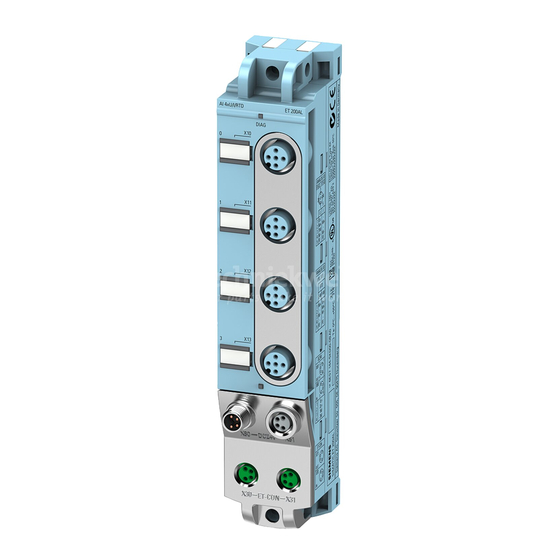
- Page 157 System overview 2.3 Components Components Components of the IO-Link I/O modules The following table shows and explains the function of the components of the IO-Link I/O modules of the ET 200AL distributed I/O system. Table 2- 1 Components of the IO-Link I/O modules Component Function View...
- Page 158 For I/O modules with high power demand, an M12-L power connector is available for an additional supply voltage. You can find information on the maximum infeed current in the technical specifications of the modules in the respective equipment manuals or on the Internet (https://support.industry.siemens.com/cs/ww/en/view/109742667). IO-Link I/O modules System Manual, 08/2021, A5E48755395-AB...
- Page 159 Application planning 3.2 Configuration of IO-Link I/O modules Configuration of IO-Link I/O modules Each ET 200AL IO-Link I/O module has an M12 A-coded plug for connection to an IO-Link master. When connecting the IO-Link I/O modules to an IP65/67 IO-Link master, pay attention to the required port class (Type A or Type B).
- Page 160 Application planning 3.2 Configuration of IO-Link I/O modules The following figure shows a connection example on an ET 200ecoPN IO-Link master with IP65/67 degree of protection. Figure 3-2 Configuration with IP65/67 IO-Link master IO-Link I/O modules System Manual, 08/2021, A5E48755395-AB...
- Page 161 Mounting Basics Introduction The IO-Link I/O modules are designed for IP65/IP67 degree of protection. This means that you can mount the modules directly in your plant. Mounting position You can mount the IO-Link I/O modules in any mounting position. Minimum clearances Maintain a minimum clearance of 2 cm from adjacent modules or other devices when mounting.
- Page 162 Mounting 4.2 Mounting modules Mounting modules Introduction The IO-Link I/O modules are designed for mounting on a level, stable surface. Thanks to the axisymmetrical drill holes in the modules, you have the option to fasten the modules on an aluminum profile using tee nuts. The following images shows the aluminum profile on which you can mount the modules.
- Page 163 • The distance between the top and bottom drill hole is identical for all modules. Mounting 30 mm wide I/O modules (front or side) Watch video sequence (https://support.industry.siemens.com/cs/ww/en/view/95886672) The 30 mm I/O modules have a fastening point at the top and bottom. The 30 mm wide I/O modules can also be side-fastened.
- Page 164 Mounting 4.2 Mounting modules The figure below shows the dimensions for fastening the 30 mm wide I/O modules using the example of the IO-Link I/O module DIQ 4+DQ 4x24VDC/0.5A 8xM8. Figure 4-2 Dimensions for mounting 30 mm wide I/O modules IO-Link I/O modules System Manual, 08/2021, A5E48755395-AB...
- Page 165 4.2 Mounting modules Mounting 45 mm I/O modules (front mounting) Watch video sequence (https://support.industry.siemens.com/cs/ww/en/view/95886672) The 45 mm wide I/O modules have a fastening point at the top and bottom. Follow the steps below to mount a 45 mm wide I/O module: 1.
- Page 166 Mounting 4.2 Mounting modules Fastening for cable ties All IO-Link I/O modules have integrated fastening points for cable ties. The fastening points are found on all four corners of the modules. The figure below shows the top left fastening point for 2.5 mm cable ties for fastening the cables.
- Page 167 Connecting Rules and regulations for operation Introduction Depending on the area of application, the IO-Link I/O modules, as an integral component of a system, must adhere to special rules. This section gives an overview of the most important rules you must follow when integrating the IO-Link I/O modules in a plant or system.
- Page 168 If there is a danger due to overvoltages, you must take lightning protection measures for internal lightning protection (e.g. lightning protection elements. You will find additional information in the Designing interference-free controllers (https://support.industry.siemens.com/cs/ww/en/view/59193566) function manual). • For 24 V DC supply: Ensure that there is an electrical protective separation of extra-low voltage (SELV/PELV) according to IEC 61010-2-201 or IEC 60950-1.
- Page 169 – Line/wire break – Cross-circuit in the cable Reference Additional information can be found in the function manual Designing interference-free controllers (https://support.industry.siemens.com/cs/ww/en/view/59193566). Operation of the IO-Link I/O modules on a grounded/ungrounded infeed Introduction Information on the overall configuration of the IO-Link I/O modules on a grounded infeed (TN-S system) is provided below.
- Page 170 Connecting 5.2 Operation of the IO-Link I/O modules on a grounded/ungrounded infeed Supply voltages Provide the IO-Link master with an SELV/PELV 1L+ supply voltage. The SELV/PELV 2L+ load voltage is supplied via the M12-A connector with port class B or via the M12-L power connector.
- Page 171 Connecting 5.2 Operation of the IO-Link I/O modules on a grounded/ungrounded infeed Overall configuration of IO-Link I/O modules The figure below shows the overall electrical configuration using the example of an IO-Link I/O module with port class A on an IO-Link master with port class A. ①...
- Page 172 Connecting 5.2 Operation of the IO-Link I/O modules on a grounded/ungrounded infeed The figure below shows the overall electrical configuration using the example of an IO-Link I/O module with port class A or B on an IO-Link master with port class A. ①...
- Page 173 Connecting 5.2 Operation of the IO-Link I/O modules on a grounded/ungrounded infeed The figure below shows the overall electrical configuration using the example of an IO-Link I/O module with port class B on an IO-Link master with port class B. ①...
- Page 174 Connecting 5.2 Operation of the IO-Link I/O modules on a grounded/ungrounded infeed Components and protective measures Various components and protective measures are stipulated for setting up a complete plant. The types of components and the degree to which the protective measures are mandatory depend on the IEC regulation that applies to your plant setup.
- Page 175 Connecting 5.3 Electrical configuration of the IO-Link I/O modules Electrical configuration of the IO-Link I/O modules Electrical isolation In the electrical configuration of the IO-Link I/O modules, there is electrical isolation between: • IO-Link 1L+: Non-switched supply voltage (electronics/sensor/load supply): Electrically isolated from 2L+ (load voltage supply) •...
- Page 176 Connecting 5.4 Connecting IO-Link I/O modules to functional ground Power supply of the configuration Up to two voltage groups are available for the ET 200AL distributed I/O system. • 1L+ via IO-Link (supply voltage / non-switched) • 2L+ via port class B or M12-L power connector (load voltage / switched) Note Connecting and disconnecting of 1L+ IO-Link, 2L+ via port class B or M12-L power connector...
- Page 177 Connecting 5.4 Connecting IO-Link I/O modules to functional ground 5.4.1 Mounting IO-Link I/O modules on a conductive surface Requirement Conductive surface for mounting of the module Required tool To connect to functional ground, you need the following tool: • Screwdriver or hexagon socket size 3 Required accessories: To connect to functional ground, you need the following accessories: •...
- Page 178 Connecting 5.4 Connecting IO-Link I/O modules to functional ground 5.4.2 Mounting IO-Link I/O modules on a non-conductive surface Requirement Non-conductive surface for mounting of the module Required tool To connect to functional ground, you need the following tool: • Screwdriver or hexagon socket size 3 •...
- Page 179 Connecting 5.4 Connecting IO-Link I/O modules to functional ground Mounting To connect IO-Link I/O modules to functional ground, proceed as follows: 1. Drill two fastening holes. 2. Strip the grounding cable. 3. Fasten the cable lug to the grounding cable. 4.
- Page 180 Connecting 5.5 Wiring Wiring Connection Connect all cables to the front side of the modules: • IO-Link to the 5-pole M12 connector (A-coded) • Signal lines to the 3-pole M8 sockets or 4/5-pole M12 sockets (A-coded) • Additional load voltage to the 5-pole M12 plug (L-coded) Requirement Wire the modules with the supply voltage off.
- Page 181 Connecting 5.5 Wiring Connecting M8 connectors To connect M8 connectors, proceed as follows: 1. Insert the plug into the respective round socket on the module. Ensure the correct alignment between plug and socket. 2. Tighten the connector using the knurled screw with a torque of 0.4 Nm. The figure below shows the connection of the M8 plugs, using the example of the IO-Link digital input module DI 8x24VDC 8xM8..
- Page 182 5.5 Wiring Pin assignment of the sockets The pin assignment of the sockets can be found in the equipment manuals of the I/O modules (https://support.industry.siemens.com/cs/ww/en/ps/14247/man) in the section on pin assignment and on the side surface of the module. Y-cable The Y-cable allows you to connect two actuators or sensors to the inputs or outputs.
- Page 183 Connecting 5.6 Marking of IO-Link I/O modules Marking of IO-Link I/O modules 5.6.1 Factory markings Introduction For better orientation, the IO-Link I/O modules are furnished with various markings that support you when configuring and connecting the modules. Marking of the interfaces The interfaces of the modules are factory-labeled.
- Page 184 Connecting 5.6 Marking of IO-Link I/O modules 5.6.2 Optional markings Introduction In addition to the factory markings, there are also optional possibilities for labeling or marking interfaces and modules on the IO-Link I/O modules. Identification label The identification labels come with each IO-Link I/O module as strips and can be machine- printed.
- Page 185 Connecting 5.6 Marking of IO-Link I/O modules 5.6.3 Mounting identification labels Introduction This section describes how to mount or remove identification labels. Required tools You need a screwdriver with 3 mm blade width (only to remove identification labels). Mounting procedure To mount an identification label, proceed as follows: 1.
- Page 186 The structure of the IODD is identical for all devices from all manufacturers. The structure of the IODD is always represented in the same manner by the IO-Link configuration tools of the master manufacturer (for Siemens, S7-PCT). This ensures that the handling is the same for all IO-Link devices regardless of the manufacturer.
- Page 187 This means the IO-Link configuration tool supports the transparent representation of the IO- Link system down to field level. Siemens provides S7-PCT for engineering of the IO-Link system. You can find the relevant device description file, software and function manuals in SIOS.
- Page 188 Configuring 6.2 IODD and Port Configuration Tool - S7-PCT S7-PCT with IODD of an IO-Link I/O module The following figure shows a section from S7-PCT with IODD of an IO-Link I/O module and the device information contained therein. Figure 6-1 S7-PCT with IODD of a device and the device information contained therein IO-Link I/O modules System Manual, 08/2021, A5E48755395-AB...
- Page 189 Commissioning Startup of the IO-Link I/O module Principle of operation The figure below shows the startup of an IO-Link I/O module on an IO-Link Master schematically as a flow chart. Figure 7-1 Startup of an ET 200AL IO-Link I/O module IO-Link I/O modules System Manual, 08/2021, A5E48755395-AB...
- Page 190 Maintenance Replacing modules Replacing IO-Link I/O modules The replacement of a module is not permitted during ongoing operation. WARNING Property damage can occur If you remove/insert modules while the power is connected, this can lead to undefined states in your system. The IO-Link I/O module may be damaged as a result.
- Page 191 Maintenance 8.1 Replacing modules Procedure To replace an IO-Link I/O module, follow these steps: 1. Ensure that no current is flowing via the outputs. 2. Completely disconnect all cables connected to the IO-Link I/O module. 3. Completely remove the fixing screws of the module 4.
- Page 192 Maintenance 8.2 Firmware update Firmware update Introduction During operation, it can become necessary to update the firmware (e.g. for function extensions). You use a firmware update to update the module firmware. Note STOP state during the update When you perform a firmware update for an IO-Link I/O module, the module goes to STOP state during the update.
- Page 193 Maintenance 8.3 Resetting a module Resetting a module Introduction With "Restore Factory Setting", the IO-Link I/O module is set to the delivery condition. All information that was saved internally on the IO-Link I/O module is deleted. Options for resetting You can reset the IO-Link I/O module in S7-PCT. You have two different possibilities for this.
- Page 194 Maintenance 8.3 Resetting a module Procedure using S7-PCT Connect the PG/PC to the PROFINET IO or PROFIBUS DP interface of the IO-Link master or to your system. Make sure that an online connection to the IO-Link I/O module exists. 1. Select an IO-Link I/O module in the project tree. 2.
- Page 195 Maintenance 8.4 Maintaining/cleaning the modules Maintaining/cleaning the modules Maintenance The IO-Link I/O modules are maintenance-free. Note Repairs Repairs to an IO-Link I/O module may only be carried out by the manufacturer. Cleaning When wired, the IO-Link I/O modules comply with degree of protection IP65/IP67 and do not require any cleaning.
- Page 196 The technical data of the individual modules can be found in the modules' manuals. If there are discrepancies between the statements in this document and the product manuals, the statements in the product manuals take priority. See also SIOS (https://support.industry.siemens.com) Standards and authorizations Currently valid markings and authorizations Note Specifications for the components of the IO-Link I/O modules The markings and approvals currently valid are printed on the IO-Link I/O modules.
- Page 197 • 2011/65/EU "Restriction of the use of certain hazardous substances in electrical and electronic equipment" (RoHS Directive) The EU Declarations of Conformity are available for the authorities in charge and are kept at the following address: SIEMENS AG Digital Industries DI FA TI COS TT P.O. Box 1963...
- Page 198 The ET 200AL IO-Link I/O modules are not intended for use in residential areas. Using the ET 200AL IO-Link I/O modules in residential areas can affect radio and television reception. Reference The certificates for the markings and approvals can be found on the Internet under Service&Support (http://www.siemens.com/automation/service&support). IO-Link I/O modules System Manual, 08/2021, A5E48755395-AB...
- Page 199 Technical specifications 9.2 Electromagnetic compatibility Electromagnetic compatibility Definition Electromagnetic compatibility is the ability of an electrical apparatus to function in a satisfactory manner in its electromagnetic environment without affecting this environment. The ET 200AL IO-Link I/O modules fulfill the requirements of the EMC law of the European Single Market.
- Page 200 Technical specifications 9.3 Transport and storage conditions Emission of radio frequency interference The table below shows the interference emission of electromagnetic fields according to EN 55011: limit class A, group 1. Table 9- 4 Interference emission of electromagnetic fields Frequency Interference emission Measuring distance...
- Page 201 You can find the values for the operating conditions in the technical specifications of the equipment manuals or on the Internet (https://support.industry.siemens.com/cs/de/en/view/109742718). Tests for mechanical ambient conditions The following table shows the type and scope of the tests for mechanical ambient conditions.
- Page 202 Technical specifications 9.5 Details on insulation, protection class, degree of protection and rated voltage Details on insulation, protection class, degree of protection and rated voltage Insulation The insulation is designed in compliance with the requirements of IEC 61010-2-201. Note For modules with 24 V DC supply voltage (SELV/PELV), electrical isolations are tested with 707 V DC (type test).
- Page 203 Technical specifications 9.6 Safety-related symbols for IP65/IP67 modules Safety-related symbols for IP65/IP67 modules The following table contains an explanation of the symbols located on your IP65/67 modules, their packaging or in the accompanying documentation. Symbol Meaning General warning sign Caution/Notice You must read the product documentation.
- Page 204 Safety-related shutdown of ET 200AL IO-Link modules Introduction The following structure describes how to shut down ET 200AL IO-Link modules in a fail-safe manner. In the configuration shown in the diagram below (e.g. with the safety shutdown device 3SK1), all digital outputs that are connected to the 2L+ and 2M supply (24 V switched) of the ET 200AL IO-Link modules are switched to the safe OFF state.
- Page 205 Safety-related shutdown of ET 200AL IO-Link modules Block diagram ① 5-wire cable for a Port Class B connection ② 3-wire cable for a Port Class A connection Figure A-1 Higher-level safety circuit of the outputs WARNING Note potential groups for safety-related shutdown When a digital output is connected to a digital input, pay attention to the potential groups.
- Page 206 Safety-related shutdown of ET 200AL IO-Link modules Note Safe electrical separation Maintain safe galvanic isolation for voltages higher than SELV/PELV. Note Selection of the IO-Link master If the safety-related shutdown is performed via the IO-Link master, ensure that the master has the appropriate safety characteristics.
- Page 207 In this FAQ, you can find the SIMATIC standard modules that are suitable for safety-related shutdown. Request German Technical Inspectorate report (Report no. SN89858T) You can request copies of the German Technical Inspectorate report at the following address: SIEMENS AG Digital Industries DI FA TI COS TT P.O. Box 1963...
- Page 208 Dimension drawings Two module widths are available for the IO-Link I/O modules. The figure below shows the height and width of the modules. The depth of the modules varies between 40 mm and 45 mm. Detailed information on the dimensions of the individual modules can be found in the equipment manuals for the IO-Link I/O modules in the section "Dimension drawing".
- Page 209 Accessories/spare parts Accessories/spare parts Accessories for the ET 200AL IO-Link I/O modules Table C- 1 Accessories for connection to an IO-Link master Designation Length Article number Cable is pre-assembled M12 CONNECTING CABLE, A-CODED 0.5 m 6XV1801-2CE50 ET 200 1.0 m 6XV1801-2CH10 Pre-assembled cable with M12 plug and M12 socket, 1.5 m...
- Page 210 UL-approved cables UL-approved cables from PHOENIX CONTACT In combination with the named cables of the manufacturer PHOENIX CONTACT, the IO-Link I/O modules of the SIMATIC ET 200AL distributed I/O system meet the requirements for UL approval. Table C- 5 Accessories for connection to an IO-Link master...
- Page 211 Accessories/spare parts C.2 UL-approved cables Table C- 7 Accessories for additional power supply Description Length Designation Article number Cable: pre-assembled 2.5 mm M12 CONNECTING CABLE, L-CODED 0.3 m SAC-4P-M12MSL/0,3-PUR/FSL 1425081 Power cable, 4-pole, PUR halogen-free, black gray RAL 0.6 m SAC-4P-M12MSL/0,6-PUR/FSL 1425082 7021, straight plug M12, coding: L, to straight socket...
- Page 212 UL-approved cables from Siemens In combination with the named cables for the connection of DI/DQ of the manufacturer Siemens, the IO-Link I/O modules of the SIMATIC ET 200AL distributed I/O devices meet the requirements for UL approval. Table C- 8...
- Page 213 Glossary IO-Link communication signal / switching signal Connection plug Physical connection between device and cable. Device Device that can send, receive or amplify data via the bus, e.g. IO device via PROFINET IO. Diagnostics Monitoring functions for the detection, localization, classification, display, and further evaluation of errors, faults, and alarms.
- Page 214 Glossary Identification data Information that is saved in modules and that supports the user in checking the plant configuration and locating hardware changes. IO-Link Standard for communication of actuators and sensors in the lowest field level. IO-Link device Distributed field device that is connected to an IO-Link master via an IO-Link cable. IO-Link I/O modules I/O modules that are connected to an IO-Link master and operated via an IO-Link connection.
- Page 215 PROFINET. Reference potential Potential from which the voltages of the circuits involved are observed and/or measured. S7-PCT S7-Port Configuration Tool = Siemens program for configuring IO-Link devices. SELV Safety Extra Low Voltage TIA Portal Totally Integrated Automation Portal The TIA Portal is the key to the full performance capability of Totally Integrated Automation.
- Page 216 Index 24 V DC supply, 25 Electrical isolation, 32 Electromagnetic compatibility, 56 Electrostatic discharge, 56 EMC, 56 EMERGENCY-STOP device, 24 Accessories, 66 Emission of radio frequency interference, 57 Ambient conditions ET 200AL Climatic, 58 Area of application, 13 Mechanical, 58 ET 200AL IO-Link modules Application, 24 Safety-related shutdown, 61...
- Page 217 Rated voltage, 59 Reference potential Grounded, 27 Ungrounded, 27 Safe electrical isolation, 27 Screws, 19 SELV, 27 Shock, 58 SIMATIC ET 200AL, 12 Sinusoidal disturbance variables, 56 Sockets, 39 Spare parts, 66 Standards, 53 IO-Link I/O modules System Manual, 08/2021, A5E48755395-AB...
- Page 219 Preface Documentation guide SIMATIC Product overview Application planning ET 200SP/ET 200AL Mixed configuration Mounting Connecting Equipment Manual Configuring Technical specifications 11/2020 A5E33344611-AD...
- Page 220 Note the following: WARNING Siemens products may only be used for the applications described in the catalog and in the relevant technical documentation. If products and components from other manufacturers are used, these must be recommended or approved by Siemens. Proper transport, storage, installation, assembly, commissioning, operation and maintenance are required to ensure that the products operate safely and without any problems.
- Page 221 Table of contents Preface ..............................4 Documentation guide ..........................6 Product overview ..........................11 BaseUnit BU-Send ......................11 3.1.1 Product overview ....................... 11 BusAdapter BA-Send 1xFC ....................13 3.2.1 Properties .......................... 13 3.2.2 Wiring and schematic circuit diagram ................. 15 3.2.3 Diagnostics by means of LED display ..................
- Page 222 Preface Purpose of the documentation This manual supplements the system manuals ET 200SP distributed I/O system and ET 200AL distributed I/O system. Functions that generally relate to the system are described in these system manuals. The information provided in this manual and in the system/function manuals supports you in commissioning the system.
- Page 223 Siemens' products and solutions undergo continuous development to make them more secure. Siemens strongly recommends that product updates are applied as soon as they are available and that the latest product versions are used. Use of product versions that are no longer supported, and failure to apply the latest updates may increase customers' exposure to cyber threats.
- Page 224 Documentation guide The documentation for the SIMATIC ET 200SP distributed I/O system is arranged into three areas. This arrangement enables you to access the specific content you require. Basic information The System Manual and Getting Started describe in detail the configuration, installation, wiring and commissioning of the SIMATIC ET 200SP distributed I/O system.
- Page 225 You must register once to use the full functionality of "mySupport". You can find "mySupport" on the Internet (https://support.industry.siemens.com/My/ww/en). "mySupport" - Documentation With "mySupport", your personal workspace, you make the best out of your Industry Online Support.
- Page 226 • Manuals, characteristics, operating manuals, certificates • Product master data You can find "mySupport" - CAx data on the Internet (http://support.industry.siemens.com/my/ww/en/CAxOnline). Application examples The application examples support you with various tools and examples for solving your automation tasks. Solutions are shown in interplay with multiple components in the system - separated from the focus on individual products.
- Page 227 You can find the SIMATIC Automation Tool on the Internet. PRONETA SIEMENS PRONETA (PROFINET network analysis) allows you to analyze the plant network during commissioning. PRONETA features two core functions: • The topology overview automatically scans the PROFINET and all connected components.
- Page 228 Documentation guide SINETPLAN SINETPLAN, the Siemens Network Planner, supports you in planning automation systems and networks based on PROFINET. The tool facilitates professional and predictive dimensioning of your PROFINET installation as early as in the planning stage. In addition, SINETPLAN supports you during network optimization and helps you to exploit network resources optimally and to plan reserves.
- Page 229 Product overview BaseUnit BU-Send 3.1.1 Product overview Article number 6ES7193-6BN00-0NE0 View Figure 3-1 BaseUnit BU-Send Properties BaseUnit suitable for BusAdapter BA-Send 1xFC Mixed configuration Equipment Manual, 11/2020, A5E33344611-AD...
- Page 230 Product overview 3.1 BaseUnit BU-Send Schematic circuit diagram ① Backplane bus ② BA-Send 1xFC expansion module Mixed configuration Equipment Manual, 11/2020, A5E33344611-AD...
- Page 231 Product overview 3.2 BusAdapter BA-Send 1xFC BusAdapter BA-Send 1xFC 3.2.1 Properties Article number 6ES7193-6AS00-0AA0 View of the module ① Module type and name ② LED for diagnostics ③ Connection for ET-Connection ④ Article number ⑤ Functional version Figure 3-2 View of the BusAdapter BA-Send 1xFC Mixed configuration Equipment Manual, 11/2020, A5E33344611-AD...
- Page 232 See also You will find additional information on accessories and the other components in the system manuals ET 200AL Distributed I/O System (http://support.automation.siemens.com/WW/view/en/89254965) and the Accessories/Spare parts section of the ET 200SP Distributed I/O System (https://support.industry.siemens.com/cs/ww/en/view/58649293) system manual. Mixed configuration...
- Page 233 Product overview 3.2 BusAdapter BA-Send 1xFC 3.2.2 Wiring and schematic circuit diagram ET-Connection with BusAdapter BA-Send 1xFC The following table shows the signal names and the designations for the pin assignment of the BusAdapter BA-Send 1xFC. Table 3- 1 ET-Connection pin assignment with BusAdapter BA-Send 1xFC View Signal name Description...
- Page 234 Product overview 3.2 BusAdapter BA-Send 1xFC 3.2.3 Diagnostics by means of LED display LED display The figure below shows the LED display (status and fault display) of the BusAdapter BA-Send 1xFC. ① DIAG (green/red) Figure 3-4 LED display Meaning of the LED display The table below explains the meaning of the status and fault display.
- Page 235 Application planning Mixed configuration ET 200SP and ET 200AL with ET-Connection You have the option of integrating the I/O modules of the ET 200AL distributed I/O system (IP65/IP67) in a configuration of the ET 200SP distributed I/O system (IP20). The figure below shows a combination of the modules of the ET 200AL and ET 200SP distributed I/O system.
- Page 236 Application planning Requirement The following components support mixed configuration: • Interface module – IM 155-6 PN HF (V3.0 or higher) – IM 155-6 PN/2 HF – IM 155-6 PN/3 HF – IM 155-6 PN ST (V3.1 or higher) – IM 155-6 DP HF (V3.0 or higher) –...
- Page 237 Application planning Rules You must observe the following rules when assembling a mixed configuration: • The bus length of the ET 200SP distributed I/O system must not exceed 1 m (without interface module, including BU-Send/BA-Send 1xFC and server module) • A maximum of 16 ET 200AL I/O modules can be connected to ET-Connection •...
- Page 238 Application planning Note Insertion of theBusAdapter BA-Send 1xFC during operation leads to a restart of the interface module. Mixed configuration Equipment Manual, 11/2020, A5E33344611-AD...
- Page 239 Mounting Introduction For the connection of the ET 200AL I/O module via ET-Connection to the ET 200SP, you require the BaseUnit BU-Send with the BusAdapter BA-Send 1xFC. Requirement • The mounting rail is mounted. • The interface module is mounted. Required tools 3 to 3.5 mm screwdriver (only for dismantling the BusAdapter) Mounting BaseUnit BU-Send...
- Page 240 Connecting Connecting BaseUnit BU-Send Pin assignment The BaseUnit BU-Send only has one slot for an expansion module. No other connections are available. Schematic circuit diagram ① Backplane bus ② BA-Send 1xFC expansion module Figure 6-1 Schematic circuit diagram BU-Send Mixed configuration Equipment Manual, 11/2020, A5E33344611-AD...
- Page 241 Connecting 6.1 Connecting BaseUnit BU-Send Introduction You connect the ET 200AL I/O modules via the BusAdapter BA-Send 1xFC via ET-Connection. ① BusAdapter BA-Send 1xFC ② Connection element for ET-Connection bus cable Figure 6-2 BusAdapter BA-Send 1xFC Required tools Screwdriver with 3 to 3.5 mm blade Required accessories Use the bus cable for ET-Connection as connecting cable between the BusAdapter BA-Send 1xFC and the ET 200AL I/O modules.
- Page 242 Connecting 6.1 Connecting BaseUnit BU-Send Procedure To connect the BusAdapter BA-Send 1xFC , follow these steps: 1. Strip the sheath of the bus cable at the open end as follows: Figure 6-3 Connecting cable Use the Stripping Tool for ET-Connection to do this. The relevant settings are shown on the tool.
- Page 243 Connecting 6.1 Connecting BaseUnit BU-Send 6. Insert and fasten the BusAdapter BA-Send 1xFC with the BaseUnit BU-Send (1 screw with tightening torque of 0.2 Nm). To do this, use a screwdriver with a 3 to 3.5 mm blade. 7. Connect the M8 connector of the bus cable to the first ET 200AL I/O module (socket X30 ET-Connection IN).
- Page 244 Connecting 6.1 Connecting BaseUnit BU-Send BusAdapter BA-Send 1xFC mounted ① BusAdapter BA-Send 1xFC ② Bus cable for ET-Connection Figure 6-5 BusAdapter BA-Send 1xFC mounted Mixed configuration Equipment Manual, 11/2020, A5E33344611-AD...
- Page 245 Configuring Introduction The mixed configuration allows the connection of up to 16 ET 200AL I/O modules to the ET 200SP via ET-Connection. The figure below shows the configuration of the ET-Connection and the assignment of the slots. ① ET 200SP I/O modules ⑤...
- Page 246 Configuring Rules Observe the following rules when configuring: • With mixed configurations, the following maximum configuration is possible: – 31 slots for ET 200SP modules (IM 155-6 DP HF and IM 155-6 PN ST) – 63 slots for ET 200SP modules (IM 155-6 PN HF and CPUs) –...
- Page 247 Configuring Configuration example An example of a mixed configuration is shown below: Hardware configuration ① ET 200SP I/O modules ⑥ 2nd ET 200AL I/O module ② ET 200SP server module ⑦ 3rd ET 200AL I/O module ③ Slots ⑧ 4th ET 200AL I/O module ④...
- Page 248 Technical specifications Technical specifications BaseUnit BU-Send Technical specifications of the BaseUnit BU-Send Article number 6ES7193-6BN00-0NE0 General information HW functional status from FS04 Ambient conditions Ambient temperature during operation -30 °C • horizontal installation, min. 60 °C • horizontal installation, max. -30 °C •...
- Page 249 Technical specifications 8.2 Technical specifications BusAdapter BA-Send 1xFC Technical specifications BusAdapter BA-Send 1xFC Technical specifications of the BusAdapter BA-Send 1xFC Article number 6ES7193-6AS00-0AA0 General information Product type designation BA-Send 1xFC HW functional status From FS05 Interfaces Supports protocol for PROFINET IO Cable length 15 m;...
- Page 251 IM 157-1 DP (6ES7157-1AA00-0AB0) Preface ET 200AL Documentation Guide SIMATIC Product overview Wiring ET 200AL IM 157-1 DP Parameters (6ES7157-1AA00-0AB0) Interrupts, error messages, diagnostics and system Equipment Manual alarms Technical specifications Dimension drawing Cycle times 08/2021 A5E32100641-AE...
- Page 252 Note the following: WARNING Siemens products may only be used for the applications described in the catalog and in the relevant technical documentation. If products and components from other manufacturers are used, these must be recommended or approved by Siemens. Proper transport, storage, installation, assembly, commissioning, operation and maintenance are required to ensure that the products operate safely and without any problems.
- Page 253 Siemens' products and solutions undergo continuous development to make them more secure. Siemens strongly recommends that product updates are applied as soon as they are available and that the latest product versions are used. Use of product versions that are no longer supported, and failure to apply the latest updates may increase customers' exposure to cyber threats.
- Page 254 Table of contents Preface ..............................3 ET 200AL Documentation Guide ......................5 Product overview ........................... 9 Properties ..........................9 Operator controls and display elements ................11 Functions .......................... 12 2.3.1 PROFIBUS DP ........................12 2.3.2 Configuration control (option handling) ................13 Wiring ..............................
- Page 255 This arrangement enables you to access the specific content you require. Basic information The System Manual and Getting Started describe in detail the configuration, installation, wiring and commissioning of the SIMATIC ET 200AL distributed I/O system. The STEP 7 online help supports you in the configuration and programming. Device information Product manuals contain a compact description of the module-specific information, such as properties, wiring diagrams, characteristics and technical specifications.
- Page 256 You must register once to use the full functionality of "mySupport". You can find "mySupport" on the Internet (https://support.industry.siemens.com/My/ww/en). "mySupport" - Documentation With "mySupport", your personal workspace, you make the best out of your Industry Online Support.
- Page 257 You can find the SIMATIC Automation Tool on the Internet (https://support.industry.siemens.com/cs/ww/en/view/98161300). PRONETA SIEMENS PRONETA (PROFINET network analysis) allows you to analyze the plant network during commissioning. PRONETA features two core functions: • The topology overview automatically scans the PROFINET and all connected components.
- Page 258 ET 200AL Documentation Guide SINETPLAN SINETPLAN, the Siemens Network Planner, supports you in planning automation systems and networks based on PROFINET. The tool facilitates professional and predictive dimensioning of your PROFINET installation as early as in the planning stage. In addition, SINETPLAN supports you during network optimization and helps you to exploit network resources optimally and to plan reserves.
- Page 259 Product overview Properties Article number 6ES7157-1AA00-0AB0 View of the module Figure 2-1 View of the IM 157-1 DP interface module IM 157-1 DP (6ES7157-1AA00-0AB0) Equipment Manual, 08/2021, A5E32100641-AE...
- Page 260 • M12 sealing cap See also You will find additional information on accessories and the other components in the Accessories/Spare parts section of the ET 200AL Distributed I/O System (http://support.automation.siemens.com/WW/view/en/89254965) system manual. IM 157-1 DP (6ES7157-1AA00-0AB0) Equipment Manual, 08/2021, A5E32100641-AE...
- Page 261 Product overview 2.2 Operator controls and display elements Operator controls and display elements The figure below shows the operator control and display elements of the interface module IM 157-1 DP. ① RUN, ERROR, MAINT: LED displays for the current operating status and diagnostics status ②...
- Page 262 DP master and the DP slaves. Reference You will find more information on PROFIBUS DP in the STEP 7 online help and in the Function Manual PROFIBUS with STEP 7 V13 (http://support.automation.siemens.com/WW/view/en/59193579). IM 157-1 DP (6ES7157-1AA00-0AB0) Equipment Manual, 08/2021, A5E32100641-AE...
- Page 263 Reference You can find more information on configuration control • In the system manual ET 200AL Distributed I/O System (https://support.industry.siemens.com/cs/ww/en/view/89254965) • On the Internet under the following link: Application collection (https://support.industry.siemens.com/cs/ww/en/view/29430270). • In the STEP 7 online help.
- Page 264 Wiring Terminal and block diagram The image below shows the terminal and block diagram of the IM 157-1 DP interface module. ① Electronics Supply voltage 1L+ (non-switched) ② ET-Connection interface Ground 1M (non-switched) ③ Internal supply voltage Load voltage 2L+ (switched) ④...
- Page 265 Wiring 3.2 Pin assignment Pin assignment Note Color coding The sockets for ET-Connection and the power supply of the modules are color-coded. These colors correspond to the colors of the offered cables. Pin assignment of the sockets for PROFIBUS The following table shows the pin assignment of the connectors and sockets for the connection of PROFIBUS.
- Page 266 Wiring 3.2 Pin assignment Pin assignment of the connector for infeed of the supply voltage The following table shows the pin assignment of the connector for infeed of the supply voltage. Table 3- 3 Pin assignment of the supply voltage connector Assignment Assignment of the Front view of the...
- Page 267 Wiring 3.3 Configuring PROFIBUS DP address and terminating resistor Configuring PROFIBUS DP address and terminating resistor Properties Use the PROFIBUS address to specify at which address the ET 200AL distributed I/O system is addressed on the PROFIBUS DP. The PROFIBUS DP address is configured for the ET 200AL distributed I/O system with a rotary coding switch on the front of the housing.
- Page 268 Wiring 3.3 Configuring PROFIBUS DP address and terminating resistor Setting the PROFIBUS DP address Configurable PROFIBUS DP addresses are 1 to 99. Proceed as follows to configure the PROFIBUS DP address: 1. Remove the two M12 sealing caps from the rotary coding switches (use 14 mm socket wrench, if needed).
- Page 269 Wiring 3.3 Configuring PROFIBUS DP address and terminating resistor The following table shows how to set PROFIBUS address 26 as an example. Table 3- 5 Setting of the PROFIBUS address Tens digit Position 2 Ones digit Position 6 Connecting the terminating resistor for PROFIBUS DP Terminate a PROFIBUS DP segment, on both of its ends, which means on the first and last device of the segment, with its characteristic impedance.
- Page 270 Parameters Parameters The following table shows the parameters for the IM 157-1 DP interface module. Table 4- 1 Parameters Parameters Value range Default Efficiency range Configuration control Disable ET 200AL • Disable • Enable Startup if preset configuration does Disable ET 200AL •...
- Page 271 Parameters 4.2 Explanation of the parameters Note Configuring the enable If you configure the enable, the ET 200AL distributed I/O system requires a control data record 196 from the user program in order for the ET 200AL distributed I/O system to operate the I/O modules.
- Page 272 Interrupts, error messages, diagnostics and system alarms Status and error displays LED displays The figure below shows the LED displays (status and error displays) of the IM 157-1 DP interface module. ① (green) ② ERROR (red) ③ MAINT (yellow) ④ ET-CON1 (green) ⑤...
- Page 273 Interrupts, error messages, diagnostics and system alarms 5.1 Status and error displays Meaning of the LEDs The following tables set out the meaning of the status and error displays. Corrective measures for diagnostics alarms can be found in the section Diagnostics alarms (Page 34). LED RUN, LED ERROR, LED MAINT Table 5- 1 Status and error displays of the LEDs RUN, ERROR, MAINT...
- Page 274 Interrupts, error messages, diagnostics and system alarms 5.1 Status and error displays DP LED Table 5- 2 Status display of the DP LED DP LED Meaning Solution There is no connection between the Check whether the bus cable to the DP PROFIBUS interface of your PROFIBUS master is disconnected.
- Page 275 Interrupts, error messages, diagnostics and system alarms 5.2 Interrupts Interrupts 5.2.1 Evaluating interrupts Introduction With certain process statuses/errors, the DP slave in each case creates an interrupt block with the corresponding information in the diagnostics frame (DPV1 interrupt mechanism). Regardless of this, the diagnostic status of the DP slave is displayed in the identifier-related diagnostics, in the module status, and in the channel diagnostics.
- Page 276 Interrupts, error messages, diagnostics and system alarms 5.2 Interrupts 5.2.4 Triggering an insert/remove module interrupt When an insert/remove module interrupt occurs, the CPU interrupts execution of the user program and processes the insert/remove module interrupt OB (OB 83). The event that triggered the interrupt is entered in the start information of the insert/remove OB.
- Page 277 Interrupts, error messages, diagnostics and system alarms 5.2 Interrupts The figure below shows the structure of data record 1. Figure 5-3 Structure of data record 1 Reading data records You have the option to read out data records 0 and 1 via SFC 59 (RD_REC) or SFB 52 (RDREC). The data length of data record 1 is up to 240 bytes.
- Page 278 Interrupts, error messages, diagnostics and system alarms 5.2 Interrupts Contents The contents of the interrupt information depend on the interrupt type: • In the case of diagnostics interrupts, diagnostics data record 1 (up to 58 bytes) is sent as interrupt status information (starting from byte x+4). •...
- Page 279 Interrupts, error messages, diagnostics and system alarms 5.2 Interrupts Diagnostics interrupt, byte x+4 to x+7 The figure below shows the structure of the diagnostics interrupt of byte x+4 to byte x+7. Figure 5-5 Structure of bytes x+4 to x+7 for diagnostics interrupt IM 157-1 DP (6ES7157-1AA00-0AB0) Equipment Manual, 08/2021, A5E32100641-AE...
- Page 280 Interrupts, error messages, diagnostics and system alarms 5.2 Interrupts Diagnostics interrupt, starting at byte x+8 The figure below shows the structure of the diagnostics interrupt starting at byte x+8. Figure 5-6 Structure starting at byte x+8 Diagnostics interrupt from the modules, starting at byte x+14 The channel error entries start from byte x+14.
- Page 281 Interrupts, error messages, diagnostics and system alarms 5.2 Interrupts The following table is used to explain the channel error entries. Description Channel number 0 … 63: Channel number for channel error 0x8000: Entire submodule Channel properties Bits 0 to 7 : Free data type : bit : 2 bit...
- Page 282 Interrupts, error messages, diagnostics and system alarms 5.2 Interrupts Example of a diagnostics interrupt The figure below shows an example of a diagnostics interrupt. Figure 5-8 Example of a diagnostics interrupt (part 1) IM 157-1 DP (6ES7157-1AA00-0AB0) Equipment Manual, 08/2021, A5E32100641-AE...
- Page 283 Interrupts, error messages, diagnostics and system alarms 5.2 Interrupts Figure 5-9 Example of a diagnostics interrupt (part 2) Hardware interrupt of digital and analog input modules, bytes x+4 to x+7 The figure below shows the structure of a hardware interrupt. Figure 5-10 Structure as of Byte x+4 for hardware interrupt Note...
- Page 284 Interrupts, error messages, diagnostics and system alarms 5.3 Alarms Alarms 5.3.1 Diagnostics alarms Actions after a diagnostics alarm in DPV1 mode The error is entered in the channel diagnostics in the diagnostics frame: • In DPV1 mode, diagnostics can be reported as diagnostics interrupts. •...
- Page 285 Interrupts, error messages, diagnostics and system alarms 5.3 Alarms 5.3.2 Slave diagnostics The figure below shows the structure of the slave diagnostics. Figure 5-11 Structure of the slave diagnostics Note The length of the diagnostics frame varies with the IM 157-1 DP (depending on parameter assignment) between 6 and 244 bytes in DPV1 mode.
- Page 286 Interrupts, error messages, diagnostics and system alarms 5.3 Alarms 5.3.3 Station statuses 1 to 3 The following tables show station status 1 to 3 and provide an overview of the status of a DP slave. Structure of station status 1 (byte 0) Table 5- 5 Structure of station status 1 (byte 0) Meaning...
- Page 287 Interrupts, error messages, diagnostics and system alarms 5.3 Alarms Structure of station status 2 (byte 1) Table 5- 6 Structure of station status 2 (byte 1) Meaning 1: The DP slave parameters need to be reassigned. 1: A diagnostics alarm is pending. The DP slave will not operate until the problem is elim- inated (static diagnostics alarm).
- Page 288 Interrupts, error messages, diagnostics and system alarms 5.3 Alarms 5.3.6 Identifier-related diagnostics The identifier-related diagnostics indicates whether modules of the ET 200AL distributed I/O system have errors or not. Identifier-related diagnostics starts at byte 6 and comprises 6 bytes. The figure below shows how the identifier-related diagnostics for the ET 200AL distributed I/O system is structured with the IM 157-1 DP interface module.
- Page 289 Interrupts, error messages, diagnostics and system alarms 5.3 Alarms 5.3.7 Module status The module status indicates the status of the configured modules and provides more information on the identifier-related diagnostics with respect to the configuration. The module status begins after the identifier-related diagnostics and comprises 13 bytes. The figure below shows how the module status for the ET 200AL distributed I/O system is structured with the IM 157-1 DP interface module.
- Page 290 Interrupts, error messages, diagnostics and system alarms 5.3 Alarms 5.3.8 Channel diagnostics Function Channel diagnostics provides information about channel errors in modules and details of the identifier-related diagnostics. Channel diagnostics begins after the module status. Channel diagnostics does not affect the module status. The figure below shows how the channel diagnostics for the ET 200AL distributed I/O system is structured with the IM 157-1 DP interface module.
- Page 291 Technical specifications of the interface module IM 157-1 DP The following table shows the technical specifications as of the issue date. You can find a data sheet including daily updated technical specifications on the Internet (https://support.industry.siemens.com/cs/ww/en/pv/6ES7157-1AA00-0AB0/td?dl=en). Article number 6ES7157-1AA00-0AB0 General information...
- Page 292 Technical specifications Article number 6ES7157-1AA00-0AB0 1. Interface Interface type PROFIBUS DP Interface types • RS 485 Yes; 2x M12 B-coded • M12 port Protocols • PROFIBUS DP slave Interface types RS 485 12 Mbit/s • Transmission rate, max. PROFIBUS DP Services –...
- Page 293 Technical specifications Article number 6ES7157-1AA00-0AB0 Highest safety class achievable for safety- related tripping of standard modules PL d • Performance level according to ISO 13849- Cat. 3 • Category according to ISO 13849-1 SILCL 2 • SILCL according to IEC 62061 Ambient conditions Ambient temperature during operation -30 °C...
- Page 294 Dimension drawing The figure below shows the dimension drawing of the IM 157-1 DP interface module in the front and side view. Figure A-1 Dimension drawing IM 157-1 DP (6ES7157-1AA00-0AB0) Equipment Manual, 08/2021, A5E32100641-AE...
- Page 295 Cycle times The following figure shows the cycle times at ET-Connection based on the number of I/O modules. Figure B-1 Cycle times The cycle time is independent of the PROFIBUS transmission rate. IM 157-1 DP (6ES7157-1AA00-0AB0) Equipment Manual, 08/2021, A5E32100641-AE...
- Page 297 Preface ET 200AL Documentation Guide SIMATIC Product overview Wiring ET 200AL IM 157-1 PN (6ES7157-1AB00-0AB0) Parameters Interrupts, error messages, diagnostics and system Equipment Manual alarms Technical specifications Dimension drawing Cycle times 05/2021 A5E32347036-AE...
- Page 298 Note the following: WARNING Siemens products may only be used for the applications described in the catalog and in the relevant technical documentation. If products and components from other manufacturers are used, these must be recommended or approved by Siemens. Proper transport, storage, installation, assembly, commissioning, operation and maintenance are required to ensure that the products operate safely and without any problems.
- Page 299 Siemens' products and solutions undergo continuous development to make them more secure. Siemens strongly recommends that product updates are applied as soon as they are available and that the latest product versions are used. Use of product versions that are no longer supported, and failure to apply the latest updates may increase customers' exposure to cyber threats.
- Page 300 Table of contents Preface ..............................3 ET 200AL Documentation Guide ......................5 Product overview ........................... 9 Properties ..........................9 Operator controls and display elements ................11 Functions .......................... 12 2.3.1 PROFINET IO ........................12 2.3.2 PROFIenergy ........................15 2.3.2.1 What is PROFlenergy? ......................15 2.3.2.2 Principle of operation ......................
- Page 301 This arrangement enables you to access the specific content you require. Basic information The System Manual and Getting Started describe in detail the configuration, installation, wiring and commissioning of the SIMATIC ET 200AL distributed I/O system. The STEP 7 online help supports you in the configuration and programming. Device information Product manuals contain a compact description of the module-specific information, such as properties, wiring diagrams, characteristics and technical specifications.
- Page 302 ET 200AL Documentation Guide Manual Collection ET 200AL The Manual Collection contains the complete documentation on the SIMATIC ET 200AL distributed I/O system gathered together in one file. You can find the Manual Collection on the Internet (https://support.automation.siemens.com/WW/view/en/95242965). "mySupport" With "mySupport", your personal workspace, you make the best out of your Industry Online Support.
- Page 303 Solutions are shown in interplay with multiple components in the system - separated from the focus on individual products. You will find the application examples on the Internet (https://support.industry.siemens.com/cs/ww/en/ps/ae). TIA Selection Tool With the TIA Selection Tool, you can select, configure and order devices for Totally Integrated Automation (TIA).
- Page 304 ET 200AL Documentation Guide PRONETA SIEMENS PRONETA (PROFINET network analysis) allows you to analyze the plant network during commissioning. PRONETA features two core functions: • The topology overview automatically scans the PROFINET and all connected components. • The IO check is a fast test of the wiring and the module configuration of a plant.
- Page 305 Product overview Properties Article number 6ES7157-1AB00-0AB0 View of the module Figure 2-1 View of the IM 157-1 PN interface module Properties The module has the following technical properties: • Connects the ET 200AL distributed I/O system with PROFINET IO • 24 V DC supply voltage •...
- Page 306 • M12 sealing cap See also You will find additional information on accessories and the other components in the Accessories/Spare parts section of the ET 200AL Distributed I/O System (http://support.automation.siemens.com/WW/view/en/89254965) system manual. IM 157-1 PN (6ES7157-1AB00-0AB0) Equipment Manual, 05/2021, A5E32347036-AE...
- Page 307 Product overview 2.2 Operator controls and display elements Operator controls and display elements The figure below shows the operator control and display elements of the interface module IM 157-1 PN. ① RUN, ERROR, MAINT: LED displays for the current operating status and diagnostics status ②...
- Page 308 Product overview 2.3 Functions Functions 2.3.1 PROFINET IO Introduction The interface module supports the following PROFINET IO functions: • Integrated switch with 2 ports • Supported Ethernet services: ping, arp, network diagnostics (SNMP)/MIB-2, LLDP • Port diagnostics • Deactivating of ports •...
- Page 309 Product overview 2.3 Functions Requirements The following table shows the software requirements for the use of PROFINET IO functions with the IM 157-1 PN interface module. Table 2- 1 Software requirements for PROFINET IO functions PROFINET IO function Configuration software STEP 7 (TIA Portal) V13 or STEP 7 V5.5 SP4 or higher higher...
- Page 310 You can find additional information in the STEP 7 online help and the manual and in the function manual PROFINET with STEP 7 V14 (http://support.automation.siemens.com/WW/view/en/49948856). Cabling with fixed connection setting If you configure a fixed connection setting for the port in STEP 7, you also have to disable "Autonegotiation/Autocrossover".
- Page 311 IO device to the delivery state with "Reset to factory settings". You will find more information on "Resetting to factory settings" in the ET 200AL Distributed I/O System (http://support.automation.siemens.com/WW/view/en/89254965) system manual in the section "Resetting interface module (PROFINET) to factory settings".
- Page 312 (https://support.industry.siemens.com/cs/ww/en/ps/14247/man) • System manual PROFINET System Description (https://support.industry.siemens.com/cs/ww/en/view/19292127) • PROFINET with STEP 7 V14 (https://support.industry.siemens.com/cs/ww/en/view/49948856), function manual, section: Saving energy with PROFIenergy • Application guide for implementation of shutdown concepts with PROFIenergy. (https://support.industry.siemens.com/cs/ww/en/view/96837137) • Saving energy with SIMATIC S7 (STEP 7 as of V5.5) (https://support.industry.siemens.com/cs/ww/en/view/41986454)
- Page 313 Product overview 2.3 Functions 2.3.2.2 Principle of operation "Pause" control and "Pause" behavior At the beginning/end of pauses, enable/disable the pause function on the system; the IO controller then sends the PROFIenergy command "Start_Pause" or "End_Pause" to the modules. The module then interprets the content of the PROFIenergy command and turns it off or on again.
- Page 314 Product overview 2.3 Functions Additional information Additional information on diagnostics can be found in the I/O module device manuals. Hardware interrupt Ending a "Pause" causes hardware interrupts to be detected again. "Pause" behavior under certain operating conditions A "Pause" is ended in the following cases: Table 2- 2 Ending a "Pause"...
- Page 315 Product overview 2.3 Functions 2.3.2.3 Parameter assignment Parameter assignment Keep the following points in mind when assigning parameters for PROFIenergy: • Parameters for PROFIenergy are assigned with the parameter data record (version 2), index 3. The interface module distributes the PROFIenergy parameters to the I/O modules. •...
- Page 316 Product overview 2.3 Functions Parameter data record You specify in the parameter data record for PROFIenergy which I/O modules (slots) are controlled with the PROFIenergy commands. The following table shows the content of the parameter data record for PROFIenergy, index 3, which you create yourself and can transfer to the interface module.
- Page 317 Reference You can find more information on configuration control • In the system manual ET 200AL Distributed I/O System (https://support.industry.siemens.com/cs/ww/en/view/89254965) • On the Internet under the following link: Application collection (https://support.industry.siemens.com/cs/ww/en/view/29430270). • In the STEP 7 online help.
- Page 318 Wiring Terminal and block diagram The image below shows the terminal and block diagram of the IM 157-1 PN interface module. ① Switch Supply voltage 1L+ (non-switched) ② Electronics Ground 1M (non-switched) ③ ET-Connection interface Load voltage 2L+ (switched) ④ Internal supply voltage Ground 2M (switched) X1 P1 R...
- Page 319 Wiring 3.2 Pin assignment Pin assignment Note Color coding The sockets for ET-Connection and the power supply of the modules are color-coded. These colors correspond to the colors of the offered cables. Pin assignment of the sockets for PROFINET The following table shows the pin assignment of the two sockets for PROFINET. Table 3- 1 Pin assignment of the PROFINET sockets Assignment...
- Page 320 Wiring 3.2 Pin assignment Pin assignment of the sockets for ET-Connection The table below shows the pin assignments of the 2 sockets for the connection of ET-Connection. Table 3- 2 Pin assignment for ET-Connection Assignment Assignment of Front view of the sockets the wire color of X30 socket X31 socket...
- Page 321 Wiring 3.2 Pin assignment Pin assignment of the socket for loop-through of the supply voltage The following table shows the pin assignment for loop-through of the supply voltage. Table 3- 4 Pin assignment of the supply voltage socket Assignment Assignment of the Front view of the wire color of the socket...
- Page 322 Parameters Parameters The following table shows the parameters for the IM 157-1 PN interface module. Table 4- 1 Parameters (GSD file) Parameters Value range Default Efficiency range Configuration control Disable ET 200AL • Disable • Enable Explanation of the parameters Configuration control You can use this parameter to enable the configuration control function in the ET 200AL distributed I/O system.
- Page 323 Interrupts, error messages, diagnostics and system alarms Status and error displays LED displays The figure below shows the LED displays (status and error displays) of the interface module IM 157-1 PN. ① (green) ② ERROR (red) ③ MAINT (yellow) ④ ET-CON1 (green) ⑤...
- Page 324 Interrupts, error messages, diagnostics and system alarms 5.1 Status and error displays Meaning of the LEDs The following tables set out the meaning of the status and error displays. Corrective measures for diagnostics alarms can be found in the section Diagnostics alarms (Page 32). LED RUN, LED ERROR, LED MAINT Table 5- 1 Status and error displays of the LEDs RUN, ERROR, MAINT...
- Page 325 Interrupts, error messages, diagnostics and system alarms 5.1 Status and error displays LED P1 LINK, LED P2 LINK Table 5- 2 Status displays of the LEDs P1 LINK and P2 LINK LEDs Meaning Solution P1 LINK P2 LINK There is no connection between the Check whether the bus cable to the switch PROFINET interface of your PROFINET de- or IO controller is disconnected.
- Page 326 Independent of the cyclic user program, messages are made available on the display of the CPU S7-1500, the CPU web server and the HMI device. You will find more information on systemic diagnostics in the Function Manual Diagnostics (http://support.automation.siemens.com/WW/view/en/59192926). 5.2.2 Trigger a diagnostics interrupt...
- Page 327 Interrupts, error messages, diagnostics and system alarms 5.2 Interrupts 5.2.3 Triggering a hardware interrupt During a hardware interrupt, the CPU interrupts the processing of the user program and processes the hardware interrupt OB (e.g., OB 40). The event that triggered the interrupt is entered in the start information of the hardware interrupt OB.
- Page 328 Additional information on the data records for PROFINET IO The structure of the diagnostics data records and programming examples can be found in the Programming Manual From PROFIBUS DP to PROFINET IO (http://support.automation.siemens.com/WW/view/en/19289930) and in the Application example (http://support.automation.siemens.com/WW/view/en/24000238). IM 157-1 PN (6ES7157-1AB00-0AB0)
- Page 329 5.3 Alarms Causes of error and troubleshooting Causes of errors and corrective measures of diagnostics alarms are described in the device manuals of the I/O modules (http://support.automation.siemens.com/WW/view/en/89013554) in the section Interrupt, Error and System Messages. 5.3.2 Maintenance events Triggering of a maintenance event The PROFINET IO interfaces of the interface module support the diagnostics concept and maintenance concept in PROFINET IO according to standard IEC 61158-6-10.
- Page 330 Interrupts, error messages, diagnostics and system alarms 5.3 Alarms 5.3.3 Channel diagnostics Function Channel-related diagnostics provides information about channel faults in modules. Channel faults are mapped as channel diagnostics data in IO diagnostics data records. The data record is read with the "RDREC" instruction (SFB 52). Structure of the diagnostics data records The data records supported by the ET 200AL distributed I/O system are based on the PROFINET IO standard - Application Layer Service definition V2.2.
- Page 331 Interrupts, error messages, diagnostics and system alarms 5.3 Alarms 5.3.5 STOP of the IO controller and recovery of the IO device STOP of the SIMATIC IO controller If diagnostics from the IO device are received by the IO controller in the STOP state, these diagnostics do not result in a start of the organization blocks after startup of the IO controller.
- Page 332 Technical specifications Technical specifications of the interface module IM 157-1 PN The following table shows the technical specifications as of 05/2021. You can find a data sheet including daily updated technical specifications on the Internet (https://support.industry.siemens.com/cs/ww/en/pv/6ES7157-1AB00-0AB0/td?dl=en). Article number 6ES7157-1AB00-0AB0 General information...
- Page 333 Technical specifications Article number 6ES7157-1AB00-0AB0 Interface types Yes; 2x M12 D-coded • M12 port • integrated switch Protocols • PROFINET IO Device • Open IE communication M12 port PROFINET with 100 Mbit/s full duplex (100BASE- • Transmission procedure Yes; for Ethernet services •...
- Page 334 Technical specifications Article number 6ES7157-1AB00-0AB0 Potential separation between the load voltages between PROFINET and all other circuits Isolation Isolation tested with 707 V DC (type test) Standards, approvals, certificates Suitable for safety-related tripping of standard Yes; From FS01 modules Highest safety class achievable for safety- related tripping of standard modules PL d •...
- Page 335 Dimension drawing The figure below shows the dimension drawing of the IM 157-1 PN interface module in the front and side view. Figure A-1 Dimension drawing IM 157-1 PN (6ES7157-1AB00-0AB0) Equipment Manual, 05/2021, A5E32347036-AE...
- Page 336 Cycle times The figure below shows the cycle times at ET-Connection based on the number of I/O modules with a PN send clock of 0.5 ms. Figure B-1 Cycle times The cycle time at ET-Connection is synchronized with the PROFINET send clock. This means that the input data of the I/O modules are transmitted via ET-Connection without further delay (wait time in the interface module) via PROFINET.
- Page 338 DI 8x24VDC 8xM8 (6ES7141-5BF00-0BA0) Preface ET 200AL Documentation Guide SIMATIC Product overview Wiring ET 200AL DI 8x24VDC 8xM8 Parameters/address space (6ES7141-5BF00-0BA0) Interrupts/diagnostics alarms Equipment Manual Technical specifications PROFIenergy Dimension drawing 08/2021 A5E32349579-AD...
- Page 339 Note the following: WARNING Siemens products may only be used for the applications described in the catalog and in the relevant technical documentation. If products and components from other manufacturers are used, these must be recommended or approved by Siemens. Proper transport, storage, installation, assembly, commissioning, operation and maintenance are required to ensure that the products operate safely and without any problems.
- Page 340 Siemens' products and solutions undergo continuous development to make them more secure. Siemens strongly recommends that product updates are applied as soon as they are available and that the latest product versions are used. Use of product versions that are no longer supported, and failure to apply the latest updates may increase customers' exposure to cyber threats.
- Page 341 Table of contents Preface ..............................3 ET 200AL Documentation Guide ......................5 Product overview ........................... 9 Properties ..........................9 Operator controls and display elements ................11 Wiring ..............................12 Terminal and block diagram ....................12 Pin assignment ........................13 Parameters/address space ........................16 Parameters ........................
- Page 342 This arrangement enables you to access the specific content you require. Basic information The System Manual and Getting Started describe in detail the configuration, installation, wiring and commissioning of the SIMATIC ET 200AL distributed I/O system. The STEP 7 online help supports you in the configuration and programming. Device information Product manuals contain a compact description of the module-specific information, such as properties, wiring diagrams, characteristics and technical specifications.
- Page 343 You must register once to use the full functionality of "mySupport". You can find "mySupport" on the Internet (https://support.industry.siemens.com/My/ww/en). "mySupport" - Documentation With "mySupport", your personal workspace, you make the best out of your Industry Online Support.
- Page 344 You can find the SIMATIC Automation Tool on the Internet (https://support.industry.siemens.com/cs/ww/en/view/98161300). PRONETA SIEMENS PRONETA (PROFINET network analysis) allows you to analyze the plant network during commissioning. PRONETA features two core functions: • The topology overview automatically scans the PROFINET and all connected components.
- Page 345 ET 200AL Documentation Guide SINETPLAN SINETPLAN, the Siemens Network Planner, supports you in planning automation systems and networks based on PROFINET. The tool facilitates professional and predictive dimensioning of your PROFINET installation as early as in the planning stage. In addition, SINETPLAN supports you during network optimization and helps you to exploit network resources optimally and to plan reserves.
- Page 346 Product overview Properties Article number 6ES7141-5BF00-0BA0 View of the module Figure 2-1 View of the DI 8x24VDC 8xM8 digital input module DI 8x24VDC 8xM8 (6ES7141-5BF00-0BA0) Equipment Manual, 08/2021, A5E32349579-AD...
- Page 347 • Stripping Tool for ET-Connection • M8 sealing cap See also You can find more information on accessories in the Accessories/spare parts section of the ET 200AL distributed I/O system (http://support.automation.siemens.com/WW/view/en/89254965) system manual. DI 8x24VDC 8xM8 (6ES7141-5BF00-0BA0) Equipment Manual, 08/2021, A5E32349579-AD...
- Page 348 Product overview 2.2 Operator controls and display elements Operator controls and display elements The following figure shows the operator controls and display elements of the DI 8x24VDC 8xM8 digital input module. ① DIAG: LED display for the diagnostic status ② X10 to X17: Sockets for the input signal ③...
- Page 349 Wiring Terminal and block diagram The following figure shows an example of the pin assignment of signal outputs with 2- and 3-wire connection. ① 2-wire connection Infeed of the ET-Connection ② 3-wire connection Loop-through of the ET-Connection ③ DI circuit Supply voltage 1L+ (non-switched) ④...
- Page 350 Wiring 3.2 Pin assignment Pin assignment Note Color coding The sockets for ET-Connection and the power supply of the modules are color-coded. These colors correspond to the colors of the offered cables. Pin assignment of the sockets for digital inputs The table below shows the pin assignment of the 8 sockets for the connection of digital inputs.
- Page 351 Wiring 3.2 Pin assignment Pin assignment of the sockets for ET-Connection The table below shows the pin assignments of the 2 sockets for the connection of ET-Connection. Table 3- 2 Pin assignment for ET-Connection Assignment Assignment of the Front view of the sockets wire color of the X30 socket X31 socket...
- Page 352 Wiring 3.2 Pin assignment Pin assignment of the socket for loop-through of the supply voltage The table below shows the pin assignment of the socket for loop-through of the supply voltage. Table 3- 4 Pin assignment of the supply voltage socket Assignment Assignment of the Front view of the...
- Page 353 Parameters/address space Parameters The following table shows the parameters for the DI 8x24VDC 8xM8 digital input module. Table 4- 1 Parameters Parameters Value range Default Scope Diagnostics: Short-circuit to ground Disable Module • Disable • Enable Explanation of the parameters Diagnostics: Short-circuit to ground Enabling of the diagnostics if a short-circuit of the encoder supply to ground occurs.
- Page 354 Parameters/address space 4.3 Address space Address space The figure below shows the assignment of the address space for the digital input module DI 8x24VDC 8xM8 with value status (Quality Information, QI). If you are using PROFINET and the value status was enabled, the addresses for the value status are available. The value status is not available for PROFIBUS.
- Page 355 Interrupts/diagnostics alarms Status and error displays LED displays The figure below shows the LED displays (status and error displays) of the DI 8x24VDC 8xM8 digital input module. ① Diagnostic status (DIAG) (red/green) ② Channel status (0 to 7) (green) Figure 5-1 LED displays DI 8x24VDC 8xM8 (6ES7141-5BF00-0BA0) Equipment Manual, 08/2021, A5E32349579-AD...
- Page 356 Interrupts/diagnostics alarms 5.1 Status and error displays Meaning of the LEDs The following tables set out the meaning of the status and error displays. Corrective measures for diagnostics alarms can be found in the section Diagnostics alarms (Page 20). DIAG LED Table 5- 1 Error display of the DIAG LED DIAG LED...
- Page 357 Interrupts/diagnostics alarms 5.2 Interrupts Interrupts The DI 8x24VDC 8xM8 digital input module supports diagnostic interrupts. Diagnostic interrupt The digital input module generates a diagnostic interrupt at the following events: • Short-circuit of encoder supply to ground Diagnostics alarms For each diagnostic event, a diagnostics alarm is issued and the DIAG LED flashes red on the digital input module.
- Page 358 Technical specifications of the DI 8x24VDC 8xM8 digital input module The following table shows the technical specifications as of the issue date. You can find a data sheet including daily updated technical specifications on the Internet (https://support.industry.siemens.com/cs/ww/en/pv/6ES7141-5BF00-0BA0/td?dl=en). Article number 6ES7141-5BF00-0BA0...
- Page 359 Technical specifications Article number 6ES7141-5BF00-0BA0 Digital inputs Number of digital inputs Input characteristic curve in accordance with IEC 61131, type 3 Number of simultaneously controllable inputs all mounting positions – up to 55 °C, max. Input voltage 24 V • Rated value (DC) -30 to +5 V •...
- Page 360 Technical specifications Article number 6ES7141-5BF00-0BA0 Potential separation channels • between the channels • between the channels and backplane bus • between the channels and the power sup- ply of the electronics Isolation Isolation tested with 707 V DC (type test) Standards, approvals, certificates Suitable for safety-related tripping of standard Yes;...
- Page 361 Additional information You can find additional information on working with PROFIenergy in the "PROFIenergy" section of the manual IM 157-1 PN interface module (http://support.automation.siemens.com/WW/view/en/89254863) and the "Saving energy with PROFIenergy" section of function manual PROFINET with STEP 7 V13 (http://support.automation.siemens.com/WW/view/en/49948856).
- Page 362 PROFIenergy 7.2 Behavior of the digital input module Behavior of the digital input module Requirement You can use the PROFIenergy function when you use the internal encoder supply. Display The channel status LEDs are directly influenced by the signal level at the socket. If the encoder supply is switched off, this causes the channel status LEDs to also switch off.
- Page 363 PROFIenergy 7.2 Behavior of the digital input module Mode parameter The following table shows the "Mode" parameter. Table 7- 1 Mode parameter Element Code Explanation Mode : PE_MODE_PROCEED Proceed at "pause" • Value status "GOOD" : PE_MODE_SHUTDOWN Switch off at "pause" •...
- Page 364 Dimension drawing The figure below shows the dimension drawing of the DI 8x24VDC 8xM8 digital input module in front and side view. Figure A-1 Dimension drawing DI 8x24VDC 8xM8 (6ES7141-5BF00-0BA0) Equipment Manual, 08/2021, A5E32349579-AD...
- Page 366 DI 8x24VDC 4xM12 (6ES7141-5AF00-0BA0) Preface ET 200AL Documentation Guide SIMATIC Product overview Wiring ET 200AL DI 8x24VDC 4xM12 Parameters/address space (6ES7141-5AF00-0BA0) Interrupts/diagnostic alarms Equipment Manual Technical specifications PROFIenergy Dimension drawing 08/2021 A5E36680963-AB...
- Page 367 Note the following: WARNING Siemens products may only be used for the applications described in the catalog and in the relevant technical documentation. If products and components from other manufacturers are used, these must be recommended or approved by Siemens. Proper transport, storage, installation, assembly, commissioning, operation and maintenance are required to ensure that the products operate safely and without any problems.
- Page 368 Siemens' products and solutions undergo continuous development to make them more secure. Siemens strongly recommends that product updates are applied as soon as they are available and that the latest product versions are used. Use of product versions that are no longer supported, and failure to apply the latest updates may increase customers' exposure to cyber threats.
- Page 369 Table of contents Preface ..............................3 ET 200AL Documentation Guide ......................5 Product overview ........................... 9 Properties ..........................9 Operator controls and display elements ................11 Wiring ..............................12 Terminal and block diagram ....................12 Pin assignment ........................13 Parameters/address space ........................16 Parameters ........................
- Page 370 This arrangement enables you to access the specific content you require. Basic information The System Manual and Getting Started describe in detail the configuration, installation, wiring and commissioning of the SIMATIC ET 200AL distributed I/O system. The STEP 7 online help supports you in the configuration and programming. Device information Product manuals contain a compact description of the module-specific information, such as properties, wiring diagrams, characteristics and technical specifications.
- Page 371 You must register once to use the full functionality of "mySupport". You can find "mySupport" on the Internet (https://support.industry.siemens.com/My/ww/en). "mySupport" - Documentation With "mySupport", your personal workspace, you make the best out of your Industry Online Support.
- Page 372 You can find the SIMATIC Automation Tool on the Internet (https://support.industry.siemens.com/cs/ww/en/view/98161300). PRONETA SIEMENS PRONETA (PROFINET network analysis) allows you to analyze the plant network during commissioning. PRONETA features two core functions: • The topology overview automatically scans the PROFINET and all connected components.
- Page 373 ET 200AL Documentation Guide SINETPLAN SINETPLAN, the Siemens Network Planner, supports you in planning automation systems and networks based on PROFINET. The tool facilitates professional and predictive dimensioning of your PROFINET installation as early as in the planning stage. In addition, SINETPLAN supports you during network optimization and helps you to exploit network resources optimally and to plan reserves.
- Page 374 Product overview Properties Article number 6ES7141-5AF00-0BA0 View of the module Figure 2-1 View of the DI 8x24VDC 4xM12 digital input module DI 8x24VDC 4xM12 (6ES7141-5AF00-0BA0) Equipment Manual, 08/2021, A5E36680963-AB...
- Page 375 • M8 sealing cap • M12 sealing cap See also You can find more information on accessories in the Accessories/spare parts section of the ET 200AL distributed I/O system (https://support.industry.siemens.com/cs/us/en/view/89254965) system manual. DI 8x24VDC 4xM12 (6ES7141-5AF00-0BA0) Equipment Manual, 08/2021, A5E36680963-AB...
- Page 376 Product overview 2.2 Operator controls and display elements Operator controls and display elements The figure below shows the operator controls and display elements of the DI 8x24VDC 4xM12 digital input module. ① DIAG: LED display for the diagnostic status ② X10 to X13: Sockets for the input signal ③...
- Page 377 Wiring Terminal and block diagram The figure below shows an example of the pin assignment of signal inputs with 2-wire and 3-wire connection. ① 3-wire connection Infeed of the ET-Connection ② 2-wire connection Loop-through of the ET-Connection ③ 2-wire connection Supply voltage 1L+ (non-switched) ④...
- Page 378 Wiring 3.2 Pin assignment Pin assignment Note Color coding The sockets for ET-Connection and the power supply of the modules are color-coded. These colors correspond to the colors of the offered cables. Pin assignment of the sockets for digital inputs The table below shows the pin assignment of the 4 sockets for the connection of digital inputs.
- Page 379 Wiring 3.2 Pin assignment Pin assignment of the sockets for ET-Connection The table below shows the pin assignments of the 2 sockets for the connection of ET-Connection. Table 3- 2 Pin assignment for ET-Connection Assignment Assignment of the Front view of the sockets wire color of the X30 socket X31 socket...
- Page 380 Wiring 3.2 Pin assignment Pin assignment of the socket for loop-through of the supply voltage The table below shows the pin assignment of the socket for loop-through of the supply voltage. Table 3- 4 Pin assignment of the supply voltage socket Assignment Assignment of the Front view of the...
- Page 381 Parameters/address space Parameters The table below shows the parameters for the DI 8x24VDC 4xM12 digital input module. Table 4- 1 Parameters Parameters Value range Default Scope Diagnostics: Short-circuit to ground Disable Module • Disable • Enable Explanation of the parameters Diagnostics: Short-circuit to ground Enabling of the diagnostics if a short-circuit of the encoder supply to ground occurs.
- Page 382 Parameters/address space 4.3 Address space Address space The figure below shows the assignment of the address space for the digital input module DI 8x24VDC 4xM12 with value status (Quality Information, QI). The address space for the value status is allocated by the module, if the value status is configured using the PROFINET interface module.
- Page 383 Interrupts/diagnostic alarms Status and error displays LED displays The figure below shows the LED displays (status and error displays) of the DI 8x24VDC 4xM12 digital input module. ① Diagnostic status (DIAG) (red/green) ② Channel status (0 to 7) (green) Figure 5-1 LED displays DI 8x24VDC 4xM12 (6ES7141-5AF00-0BA0) Equipment Manual, 08/2021, A5E36680963-AB...
- Page 384 Interrupts/diagnostic alarms 5.1 Status and error displays Meaning of the LEDs The following tables set out the meaning of the status and error displays. Corrective measures for diagnostics alarms can be found in section Diagnostics alarms (Page 20). DIAG LED Table 5- 1 Error display of the DIAG LED DIAG LED...
- Page 385 Interrupts/diagnostic alarms 5.2 Interrupts Interrupts The DI 8x24VDC 4xM12 digital input module supports diagnostic interrupts. Diagnostic interrupt The digital input module generates a diagnostic interrupt at the following events: • Short-circuit of encoder supply to ground Diagnostics alarms For each diagnostic event, a diagnostics alarm is issued and the DIAG LED flashes red on the digital input module.
- Page 386 Technical specifications of the DI 8x24VDC 4xM12 digital input module The following table shows the technical specifications as of the issue date. You can find a data sheet including daily updated technical specifications on the Internet (https://support.industry.siemens.com/cs/ww/en/pv/6ES7141-5AF00-0BA0/td?dl=en). Article number 6ES7141-5AF00-0BA0...
- Page 387 Technical specifications 6.1 Technical specifications Article number 6ES7141-5AF00-0BA0 Power loss Power loss, typ. 1.9 W Digital inputs Number of digital inputs Input characteristic curve in accordance with IEC 61131, type 3 Number of simultaneously controllable inputs all mounting positions – up to 55 °C, max.
- Page 388 Technical specifications 6.1 Technical specifications Article number 6ES7141-5AF00-0BA0 Potential separation channels • between the channels • between the channels and backplane bus • between the channels and the power sup- ply of the electronics Isolation Isolation tested with 707 V DC (type test) Standards, approvals, certificates Suitable for safety-related tripping of standard Yes;...
- Page 389 Additional information You can find additional information on working with PROFIenergy in the "PROFIenergy" section of the manual IM 157-1 PN interface module (https://support.industry.siemens.com/cs/ww/en/view/89254863) and the "Saving energy with PROFIenergy" section of function manual PROFINET with STEP 7 V13 (https://support.industry.siemens.com/cs/ww/en/view/49948856).
- Page 390 PROFIenergy 7.2 Behavior of the digital input module Behavior of the digital input module Display The channel status LEDs are directly influenced by the signal level at the socket. If the encoder supply is switched off, this causes the channel status LEDs to also switch off. Response to error detection All channels that are in pause mode on "PE_MODE_PROCEED"...
- Page 391 Dimension drawing The figure below shows the dimension drawing of the DI 8x24VDC 4xM12 digital input module in front and side view. Figure A-1 Dimension drawing DI 8x24VDC 4xM12 (6ES7141-5AF00-0BA0) Equipment Manual, 08/2021, A5E36680963-AB...
- Page 393 DI 16x24VDC 8xM12 (6ES7141-5AH00-0BA0) Preface ET 200AL Documentation Guide SIMATIC Product overview Wiring ET 200AL DI 16x24VDC 8xM12 Parameters/address space (6ES7141-5AH00-0BA0) Interrupts/diagnostic alarms Equipment Manual Technical specifications PROFIenergy Dimension drawing 08/2021 A5E36681813-AB...
- Page 394 Note the following: WARNING Siemens products may only be used for the applications described in the catalog and in the relevant technical documentation. If products and components from other manufacturers are used, these must be recommended or approved by Siemens. Proper transport, storage, installation, assembly, commissioning, operation and maintenance are required to ensure that the products operate safely and without any problems.
- Page 395 Siemens' products and solutions undergo continuous development to make them more secure. Siemens strongly recommends that product updates are applied as soon as they are available and that the latest product versions are used. Use of product versions that are no longer supported, and failure to apply the latest updates may increase customers' exposure to cyber threats.
- Page 396 Table of contents Preface ..............................3 ET 200AL Documentation Guide ......................5 Product overview ........................... 9 Properties ..........................9 Operator controls and display elements ................11 Wiring ..............................12 Terminal and block diagram ....................12 Pin assignment ........................13 Parameters/address space ........................16 Parameters ........................
- Page 397 This arrangement enables you to access the specific content you require. Basic information The System Manual and Getting Started describe in detail the configuration, installation, wiring and commissioning of the SIMATIC ET 200AL distributed I/O system. The STEP 7 online help supports you in the configuration and programming. Device information Product manuals contain a compact description of the module-specific information, such as properties, wiring diagrams, characteristics and technical specifications.
- Page 398 You must register once to use the full functionality of "mySupport". You can find "mySupport" on the Internet (https://support.industry.siemens.com/My/ww/en). "mySupport" - Documentation With "mySupport", your personal workspace, you make the best out of your Industry Online Support.
- Page 399 You can find the SIMATIC Automation Tool on the Internet (https://support.industry.siemens.com/cs/ww/en/view/98161300). PRONETA SIEMENS PRONETA (PROFINET network analysis) allows you to analyze the plant network during commissioning. PRONETA features two core functions: • The topology overview automatically scans the PROFINET and all connected components.
- Page 400 ET 200AL Documentation Guide SINETPLAN SINETPLAN, the Siemens Network Planner, supports you in planning automation systems and networks based on PROFINET. The tool facilitates professional and predictive dimensioning of your PROFINET installation as early as in the planning stage. In addition, SINETPLAN supports you during network optimization and helps you to exploit network resources optimally and to plan reserves.
- Page 401 Product overview Properties Article number 6ES7141-5AH00-0BA0 View of the module Figure 2-1 View of the DI 16x24VDC 8xM12 digital input module DI 16x24VDC 8xM12 (6ES7141-5AH00-0BA0) Equipment Manual, 08/2021, A5E36681813-AB...
- Page 402 • M8 sealing cap • M12 sealing cap See also You can find more information on accessories in the Accessories/spare parts section of the ET 200AL distributed I/O system (https://support.industry.siemens.com/cs/us/en/view/89254965) system manual. DI 16x24VDC 8xM12 (6ES7141-5AH00-0BA0) Equipment Manual, 08/2021, A5E36681813-AB...
- Page 403 Product overview 2.2 Operator controls and display elements Operator controls and display elements The figure below shows the operator controls and display elements of the DI 16x24VDC 8xM12 digital input module. ① DIAG: LED display for the diagnostic status ② X10 to X17: Sockets for the input signal ③...
- Page 404 Wiring Terminal and block diagram The figure below shows an example of the pin assignment of signal inputs with 2-wire and 3-wire connection. ① 3-wire connection Infeed of the ET-Connection ② 2-wire connection Loop-through of the ET-Connection ③ 2-wire connection Supply voltage 1L+ (non-switched) ④...
- Page 405 Wiring 3.2 Pin assignment Pin assignment Note Color coding The sockets for ET-Connection and the power supply of the modules are color-coded. These colors correspond to the colors of the offered cables. Pin assignment of the sockets for digital inputs The table below shows the pin assignment of the 8 sockets for the connection of digital inputs.
- Page 406 Wiring 3.2 Pin assignment Pin assignment of the sockets for ET-Connection The table below shows the pin assignments of the 2 sockets for the connection of ET-Connection. Table 3- 2 Pin assignment for ET-Connection Assignment Assignment of the Front view of the sockets wire color of the X30 socket X31 socket...
- Page 407 Wiring 3.2 Pin assignment Pin assignment of the socket for loop-through of the supply voltage The table below shows the pin assignment of the socket for loop-through of the supply voltage. Table 3- 4 Pin assignment of the supply voltage socket Assignment Assignment of the Front view of the...
- Page 408 Parameters/address space Parameters The table below shows the parameters for the DI 16x24VDC 8xM12 digital input module. Table 4- 1 Parameters Parameters Value range Default Scope Diagnostics: Short-circuit to ground Disable Module • Disable • Enable Explanation of the parameters Diagnostics: Short-circuit to ground Enabling of the diagnostics if a short-circuit of the encoder supply to ground occurs.
- Page 409 Parameters/address space 4.3 Address space Address space The figure below shows the assignment of the address space for the digital input module DI 16x24VDC 8xM12 with value status (Quality Information, QI). The address space for the value status is allocated by the module, if the value status is configured using the PROFINET interface module.
- Page 410 Interrupts/diagnostic alarms Status and error displays LED displays The figure below shows the LED displays (status and error displays) of the DI 16x24VDC 8xM12 digital input module. ① Diagnostic status (DIAG) (red/green) ② Channel status (0 to 15) (green) Figure 5-1 LED displays DI 16x24VDC 8xM12 (6ES7141-5AH00-0BA0) Equipment Manual, 08/2021, A5E36681813-AB...
- Page 411 Interrupts/diagnostic alarms 5.1 Status and error displays Meaning of the LEDs The following tables set out the meaning of the status and error displays. Corrective measures for diagnostics alarms can be found in section Diagnostics alarms (Page 20). DIAG LED Table 5- 1 Error display of the DIAG LED DIAG LED...
- Page 412 Interrupts/diagnostic alarms 5.2 Interrupts Interrupts The DI 16x24VDC 8xM12 digital input module supports diagnostic interrupts. Diagnostic interrupt The digital input module generates a diagnostic interrupt at the following events: • Short-circuit of encoder supply to ground Diagnostics alarms For each diagnostic event, a diagnostics alarm is issued and the DIAG LED flashes red on the digital input module.
- Page 413 Technical specifications of the DI 16x24VDC 8xM12 digital input module The following table shows the technical specifications as of the issue date. You can find a data sheet including daily updated technical specifications on the Internet (https://support.industry.siemens.com/cs/ww/en/pv/6ES7141-5AH00-0BA0/td?dl=en). Article number 6ES7141-5AH00-0BA0...
- Page 414 Technical specifications 6.1 Technical specifications Article number 6ES7141-5AH00-0BA0 Power loss Power loss, typ. 2.7 W Digital inputs Number of digital inputs Input characteristic curve in accordance with IEC 61131, type 3 Number of simultaneously controllable inputs all mounting positions – up to 55 °C, max.
- Page 415 Technical specifications 6.1 Technical specifications Article number 6ES7141-5AH00-0BA0 Potential separation channels • between the channels • between the channels and backplane bus • between the channels and the power sup- ply of the electronics Isolation Isolation tested with 707 V DC (type test) Standards, approvals, certificates Suitable for safety-related tripping of standard Yes;...
- Page 416 Additional information You can find additional information on working with PROFIenergy in the "PROFIenergy" section of the manual IM 157-1 PN interface module (https://support.industry.siemens.com/cs/ww/en/view/89254863) and the "Saving energy with PROFIenergy" section of function manual PROFINET with STEP 7 V13 (https://support.industry.siemens.com/cs/ww/en/view/49948856).
- Page 417 PROFIenergy 7.2 Behavior of the digital input module Behavior of the digital input module Display The channel status LEDs are directly influenced by the signal level at the socket. If the encoder supply is switched off, this causes the channel status LEDs to also switch off. Response to error detection All channels that are in pause mode on "PE_MODE_PROCEED"...
- Page 418 Dimension drawing The figure below shows the dimension drawing of the DI 16x24VDC 8xM12 digital input module in front and side view. Figure A-1 Dimension drawing DI 16x24VDC 8xM12 (6ES7141-5AH00-0BA0) Equipment Manual, 08/2021, A5E36681813-AB...
- Page 420 Digital input/digital output module DIQ 4+DQ 4x24VDC/0.5A 8xM8 (6ES7143-5BF00- Preface 0BA0) ET 200AL Documentation Guide SIMATIC Product overview Wiring ET 200AL Digital input/digital output Parameters/address space module DIQ 4+DQ 4x24VDC/0.5A 8xM8 Interrupts/diagnostics (6ES7143-5BF00-0BA0) alarms Equipment Manual Technical specifications PROFIenergy Dimension drawing 08/2021 A5E32349882-AD...
- Page 421 Note the following: WARNING Siemens products may only be used for the applications described in the catalog and in the relevant technical documentation. If products and components from other manufacturers are used, these must be recommended or approved by Siemens. Proper transport, storage, installation, assembly, commissioning, operation and maintenance are required to ensure that the products operate safely and without any problems.
- Page 422 Siemens' products and solutions undergo continuous development to make them more secure. Siemens strongly recommends that product updates are applied as soon as they are available and that the latest product versions are used. Use of product versions that are no longer supported, and failure to apply the latest updates may increase customers' exposure to cyber threats.
- Page 423 Table of contents Preface ..............................3 ET 200AL Documentation Guide ......................5 Product overview ........................... 9 Properties ..........................9 Operator controls and display elements ................12 Wiring ..............................13 Terminal and block diagram ....................13 Pin assignment ........................14 Parameters/address space ........................17 Parameters ........................
- Page 424 This arrangement enables you to access the specific content you require. Basic information The System Manual and Getting Started describe in detail the configuration, installation, wiring and commissioning of the SIMATIC ET 200AL distributed I/O system. The STEP 7 online help supports you in the configuration and programming. Device information Product manuals contain a compact description of the module-specific information, such as properties, wiring diagrams, characteristics and technical specifications.
- Page 425 You must register once to use the full functionality of "mySupport". You can find "mySupport" on the Internet (https://support.industry.siemens.com/My/ww/en). "mySupport" - Documentation With "mySupport", your personal workspace, you make the best out of your Industry Online Support.
- Page 426 You can find the SIMATIC Automation Tool on the Internet (https://support.industry.siemens.com/cs/ww/en/view/98161300). PRONETA SIEMENS PRONETA (PROFINET network analysis) allows you to analyze the plant network during commissioning. PRONETA features two core functions: • The topology overview automatically scans the PROFINET and all connected components.
- Page 427 ET 200AL Documentation Guide SINETPLAN SINETPLAN, the Siemens Network Planner, supports you in planning automation systems and networks based on PROFINET. The tool facilitates professional and predictive dimensioning of your PROFINET installation as early as in the planning stage. In addition, SINETPLAN supports you during network optimization and helps you to exploit network resources optimally and to plan reserves.
- Page 428 Product overview Properties Article number 6ES7143-5BF00-0BA0 View of the module Figure 2-1 View of the DIQ 4+DQ 4x24VDC/0,5A 8xM8 digital input/digital output module Digital input/digital output module DIQ 4+DQ 4x24VDC/0.5A 8xM8 (6ES7143-5BF00-0BA0) Equipment Manual, 08/2021, A5E32349882-AD...
- Page 429 Product overview 2.1 Properties Properties The module has the following technical properties: • 4 digital inputs or digital outputs and 4 digital outputs, depending on parameter assignment – DIQ signals connected to 1L+ (non-switched) – DQ signals connected to 2L+ (switched) •...
- Page 430 • M8 sealing cap See also You can find more information on accessories in the Accessories/spare parts section of the ET 200AL distributed I/O system (http://support.automation.siemens.com/WW/view/en/89254965) system manual. Digital input/digital output module DIQ 4+DQ 4x24VDC/0.5A 8xM8 (6ES7143-5BF00-0BA0) Equipment Manual, 08/2021, A5E32349882-AD...
- Page 431 Product overview 2.2 Operator controls and display elements Operator controls and display elements The following figure shows the operator controls and display elements of the DIQ 4+DQ 4x24VDC/0.5A 8xM8 digital input/digital output module. ① DIAG: LED display for the diagnostic status ②...
- Page 432 Wiring Terminal and block diagram The following figure shows an example of the pin assignment of signal inputs with 2- and 3-wire connection as well as signal outputs. ① Configured as output Infeed of the ET-Connection ② Configured as input: 2-wire connection Loop-through of the ET-Connection ③...
- Page 433 Wiring 3.2 Pin assignment Pin assignment Note Color coding The sockets for ET-Connection and the power supply of the modules are color-coded. These colors correspond to the colors of the offered cables. Pin assignment of the sockets for digital inputs/digital outputs The tables below show the pin assignments of the 8 sockets for connection of the digital inputs/digital outputs.
- Page 434 Wiring 3.2 Pin assignment Pin assignment of the sockets for ET-Connection The table below shows the pin assignments of the 2 sockets for the connection of ET-Connection. Table 3- 3 Pin assignment for ET-Connection Assignment Assignment of the Front view of the sockets wire color of the X30 socket X31 socket...
- Page 435 Wiring 3.2 Pin assignment NOTICE ET-Connection/supply voltage Observe the correct wiring of the M8 sockets for ET-Connection and the supply voltage. Mixing up the ET-Connection connectors and the connectors for the supply voltage can destroy the module. Digital input/digital output module DIQ 4+DQ 4x24VDC/0.5A 8xM8 (6ES7143-5BF00-0BA0) Equipment Manual, 08/2021, A5E32349882-AD...
- Page 436 Parameters/address space Parameters The following table shows the parameters for the DIQ 4+DQ 4x24VDC/0.5A 8xM8 digital input/digital output module. Table 4- 1 Parameters Parameters Value range Default Scope Diagnostics: Missing load voltage 2L+ • Disable Module Disable • Enable Diagnostics: Short-circuit to ground Disable Module •...
- Page 437 Parameters/address space 4.2 Explanation of the parameters Explanation of the parameters Diagnostics: Missing load voltage 2L+ Enabling of the diagnostics for missing or insufficient load voltage 2L+. Diagnostics: Short-circuit to ground Enabling of the diagnostics for short-circuit of the encoder supply or output to ground. Freely assignable channel n With this parameter, you set whether the channel is to be operated as an input or output.
- Page 438 Parameters/address space 4.3 Address space Address space The figure below shows the assignment of the address space for the digital input/digital output module DIQ 4+DQ 4x24VDC/0.5A 8xM8 with value status (Quality Information, QI). The address space for the value status is allocated by the module, if the value status is configured using the PROFINET interface module.
- Page 439 Parameters/address space 4.3 Address space Configuration options of the digital input/digital output module DIQ 4+DQ 4x24VDC/0.5A 8xM8 You have the following configuration options: • Configuration 1: without value status • Configuration 2: with value status Evaluating the value status An additional two bytes are occupied in the input address space if you enable the value status for the digital input/digital output module.
- Page 440 Interrupts/diagnostics alarms Status and error displays LED displays The figure below shows the LED displays (status and error displays) of the digital input/digital output module DIQ 4+DQ 4x24VDC/0.5A 8xM8. ① Diagnostic status (DIAG) (red/green) ② Channel status (0 to 7) (green) ③...
- Page 441 Interrupts/diagnostics alarms 5.1 Status and error displays Meaning of the LEDs The following tables set out the meaning of the status and error displays. Corrective measures for diagnostics alarms can be found in the section Diagnostics alarms (Page 23). DIAG LED Table 5- 1 Error display of the DIAG LED DIAG LED...
- Page 442 Interrupts/diagnostics alarms 5.2 Interrupts Interrupts The DIQ 4+DQ 4x24VDC/0.5A 8xM8 digital input/digital output module supports diagnostic interrupts. Diagnostic interrupt The digital input/digital output module generates a diagnostic interrupt at the following events: • Short-circuit of encoder supply to ground • Short-circuit of outputs to ground •...
- Page 443 Technical specifications of the DIQ 4+DQ 4x24VDC/0.5A 8xM8 digital input/digital output module The following table shows the technical specifications as of the issue date. You can find a data sheet including daily updated technical specifications on the Internet (https://support.industry.siemens.com/cs/ww/en/pv/6ES7143-5BF00-0BA0/td?dl=en). Article number 6ES7143-5BF00-0BA0...
- Page 444 Technical specifications Article number 6ES7143-5BF00-0BA0 Encoder supply Number of outputs 24 V encoder supply Yes; per module, electronic • Short-circuit protection 0.7 A; Total current of all encoders • Output current, max. Power loss Power loss, typ. 2.5 W Digital inputs Number of digital inputs 4;...
- Page 445 Technical specifications Article number 6ES7143-5BF00-0BA0 Output voltage L+ (-0.8 V) • for signal "1", min. Output current 0.5 A • for signal "1" rated value 0.5 mA • for signal "0" residual current, max. Switching frequency 100 Hz • with resistive load, max. 0.5 Hz •...
- Page 446 Technical specifications Article number 6ES7143-5BF00-0BA0 Standards, approvals, certificates Suitable for safety-related tripping of standard Yes; From FS01 modules Highest safety class achievable for safety- related tripping of standard modules PL d • Performance level according to ISO 13849- Cat. 3 •...
- Page 447 Additional information You can find additional information on working with PROFIenergy in the "PROFIenergy" section of the manual IM 157-1 PN interface module (http://support.automation.siemens.com/WW/view/en/89254863) and the "Saving energy with PROFIenergy" section of function manual PROFINET with STEP 7 V13 (http://support.automation.siemens.com/WW/view/en/49948856).
- Page 448 PROFIenergy 7.2 DI operating mode DI operating mode Display The channel status LEDs are directly influenced by the signal level at the socket. If the encoder supply is switched off, this causes the channel status LEDs to also switch off. Response to error detection All channels that are in pause mode on "PE_MODE_PROCEED"...
- Page 449 PROFIenergy 7.3 DQ operating mode DQ operating mode Display The channel status LEDs are directly affected by the signal level at the socket. Response to error detection All channels that are in pause mode on "PE_MODE_PROCEED" report their diagnostic status as in productive mode.
- Page 450 Dimension drawing The following figure shows the dimension drawing of the DIQ 4+DQ 4x24VDC/0.5A 8xM8 digital input/digital output module in front and side views. Figure A-1 Dimension drawing Digital input/digital output module DIQ 4+DQ 4x24VDC/0.5A 8xM8 (6ES7143-5BF00-0BA0) Equipment Manual, 08/2021, A5E32349882-AD...
- Page 452 Digital input/digital output module DIQ 4+DQ 4x24VDC/0.5A 4xM12 (6ES7143-5AF00- Preface 0BA0) ET 200AL Documentation Guide SIMATIC Product overview Wiring ET 200AL Digital input/digital output module Parameters/address space DIQ 4+DQ 4x24VDC/0.5A 4xM12 (6ES7143-5AF00-0BA0) Interrupts/diagnostic alarms Technical specifications Equipment Manual PROFIenergy Dimension drawing 08/2021 A5E36683613-AB...
- Page 453 Note the following: WARNING Siemens products may only be used for the applications described in the catalog and in the relevant technical documentation. If products and components from other manufacturers are used, these must be recommended or approved by Siemens. Proper transport, storage, installation, assembly, commissioning, operation and maintenance are required to ensure that the products operate safely and without any problems.
- Page 454 Siemens' products and solutions undergo continuous development to make them more secure. Siemens strongly recommends that product updates are applied as soon as they are available and that the latest product versions are used. Use of product versions that are no longer supported, and failure to apply the latest updates may increase customers' exposure to cyber threats.
- Page 455 Table of contents Preface ..............................3 ET 200AL Documentation Guide ......................5 Product overview ........................... 9 Properties ..........................9 Operator controls and display elements ................12 Wiring ..............................13 Terminal and block diagram ....................13 Pin assignment ........................14 Parameters/address space ........................17 Parameters ........................
- Page 456 This arrangement enables you to access the specific content you require. Basic information The System Manual and Getting Started describe in detail the configuration, installation, wiring and commissioning of the SIMATIC ET 200AL distributed I/O system. The STEP 7 online help supports you in the configuration and programming. Device information Product manuals contain a compact description of the module-specific information, such as properties, wiring diagrams, characteristics and technical specifications.
- Page 457 You must register once to use the full functionality of "mySupport". You can find "mySupport" on the Internet (https://support.industry.siemens.com/My/ww/en). "mySupport" - Documentation With "mySupport", your personal workspace, you make the best out of your Industry Online Support.
- Page 458 You can find the SIMATIC Automation Tool on the Internet (https://support.industry.siemens.com/cs/ww/en/view/98161300). PRONETA SIEMENS PRONETA (PROFINET network analysis) allows you to analyze the plant network during commissioning. PRONETA features two core functions: • The topology overview automatically scans the PROFINET and all connected components.
- Page 459 ET 200AL Documentation Guide SINETPLAN SINETPLAN, the Siemens Network Planner, supports you in planning automation systems and networks based on PROFINET. The tool facilitates professional and predictive dimensioning of your PROFINET installation as early as in the planning stage. In addition, SINETPLAN supports you during network optimization and helps you to exploit network resources optimally and to plan reserves.
- Page 460 Product overview Properties Article number 6ES7143-5AF00-0BA0 View of the module Figure 2-1 View of the DIQ 4+DQ 4x24VDC/0.5A 4xM12 digital input/digital output module Digital input/digital output module DIQ 4+DQ 4x24VDC/0.5A 4xM12 (6ES7143-5AF00-0BA0) Equipment Manual, 08/2021, A5E36683613-AB...
- Page 461 Product overview 2.1 Properties Properties The module has the following technical properties: • 4 digital inputs or digital outputs and 4 digital outputs, depending on parameter assignment – DIQ signals connected to 1L+ (non-switched) – DQ signals connected to 2L+ (switched) •...
- Page 462 • M12 sealing cap See also You can find more information on accessories in the Accessories/spare parts section of the ET 200AL distributed I/O system (https://support.industry.siemens.com/cs/us/en/view/89254965) system manual. Digital input/digital output module DIQ 4+DQ 4x24VDC/0.5A 4xM12 (6ES7143-5AF00-0BA0) Equipment Manual, 08/2021, A5E36683613-AB...
- Page 463 Product overview 2.2 Operator controls and display elements Operator controls and display elements The figure below shows the operator controls and display elements of the DIQ 4+DQ 4x24VDC/0.5A 4xM12 digital input/digital output module. ① DIAG: LED display for the diagnostic status ②...
- Page 464 Wiring Terminal and block diagram The figure below shows an example of the pin assignment of signal inputs with 2-wire and 3-wire connection as well as signal outputs. ① Configured as input: 3-wire connection Infeed of the ET-Connection ② Configured as output Loop-through of the ET-Connection ③...
- Page 465 Wiring 3.2 Pin assignment Pin assignment Note Color coding The sockets for ET-Connection and the power supply of the modules are color-coded. These colors correspond to the colors of the offered cables. Pin assignment of the sockets for digital inputs/digital outputs The tables below show the pin assignments of the 4 sockets for connection of the digital inputs/digital outputs.
- Page 466 Wiring 3.2 Pin assignment Pin assignment of the sockets for ET-Connection The table below shows the pin assignments of the 2 sockets for the connection of ET-Connection. Table 3- 3 Pin assignment for ET-Connection Assignment Assignment of the Front view of the sockets wire color of the X30 socket X31 socket...
- Page 467 Wiring 3.2 Pin assignment Pin assignment of the socket for loop-through of the supply voltage The table below shows the pin assignment of the socket for loop-through of the supply voltage. Table 3- 5 Pin assignment of the supply voltage socket Assignment Assignment of the Front view of the...
- Page 468 Parameters/address space Parameters The table below shows the parameters for the DIQ 4+DQ 4x24VDC/0.5A 4xM12 digital input/digital output module. Table 4- 1 Parameters Parameters Value range Default Scope Diagnostics: Missing load voltage 2L+ • Disable Module Disable • Enable Diagnostics: Short-circuit to ground Disable Module •...
- Page 469 Parameters/address space 4.2 Explanation of the parameters Explanation of the parameters Diagnostics: Missing load voltage 2L+ Enabling of the diagnostics for missing or insufficient load voltage 2L+. Diagnostics: Short-circuit to ground Enabling of the diagnostics for short-circuit of the encoder supply or output to ground. Freely assignable channel n With this parameter, you set whether the channel is to be operated as an input or output.
- Page 470 Parameters/address space 4.3 Address space Address space The figure below shows the assignment of the address space for the digital input/digital output module DIQ 4+DQ 4x24VDC/0.5A 4xM12 with value status (Quality Information, QI). The address space for the value status is allocated by the module, if the value status is configured using the PROFINET interface module.
- Page 471 Parameters/address space 4.3 Address space Evaluating the value status An additional two bytes are occupied in the input address space if you enable the value status for the digital input/digital output module. The value status of the inputs is assigned to bits 0 to 3 in input byte x + 1.
- Page 472 Interrupts/diagnostic alarms Status and error displays LED displays The figure below shows the LED displays (status and error displays) of the digital input/ digital output module DIQ 4+DQ 4x24VDC/0.5A 4xM12. ① Diagnostic status (DIAG) (red/green) ② Channel status (0 to 7) (green) ③...
- Page 473 Interrupts/diagnostic alarms 5.1 Status and error displays Meaning of the LEDs The following tables set out the meaning of the status and error displays. Remedial measures for diagnostic alarms can be found in the section Diagnostics alarms (Page 23). DIAG LED Table 5- 1 Error display of the DIAG LED DIAG LED...
- Page 474 Interrupts/diagnostic alarms 5.2 Interrupts Interrupts The DIQ 4+DQ 4x24VDC/0.5A 4xM12 digital input/digital output module supports diagnostic interrupts. Diagnostic interrupt The digital input/digital output module generates a diagnostic interrupt at the following events: • Short-circuit of encoder supply to ground • Short-circuit of outputs to ground •...
- Page 475 Technical specifications of the DIQ 4+DQ 4x24VDC/0.5A 4xM12 digital input/digital output module The following table shows the technical specifications as of the issue date. You can find a data sheet including daily updated technical specifications on the Internet (https://support.industry.siemens.com/cs/ww/en/pv/6ES7143-5AF00-0BA0/td?dl=en). Article number 6ES7143-5AF00-0BA0 General information Product type designation DIQ 4+DQ 4x24VDC/0.5A...
- Page 476 Technical specifications 6.1 Technical specifications Article number 6ES7143-5AF00-0BA0 Input current Current consumption (rated value) 40 mA; without load from load voltage 1L+ (unswitched voltage) 4 A; Maximum value from load voltage 2L+, max. 4 A; Maximum value Encoder supply Number of outputs 24 V encoder supply Yes;...
- Page 477 Technical specifications 6.1 Technical specifications Article number 6ES7143-5AF00-0BA0 Load resistance range 48 Ω • lower limit 4 kΩ • upper limit Output voltage L+ (-0.8 V) • for signal "1", min. Output current 0.5 A • for signal "1" rated value 0.5 mA •...
- Page 478 Technical specifications 6.1 Technical specifications Article number 6ES7143-5AF00-0BA0 Isolation Isolation tested with 707 V DC (type test) Standards, approvals, certificates Suitable for safety-related tripping of standard Yes; From FS01 modules Highest safety class achievable for safety- related tripping of standard modules PL d •...
- Page 479 Additional information You can find additional information on working with PROFIenergy in the "PROFIenergy" section of the manual IM 157-1 PN interface module (https://support.industry.siemens.com/cs/ww/en/view/89254863) and the "Saving energy with PROFIenergy" section of function manual PROFINET with STEP 7 V13 (https://support.industry.siemens.com/cs/ww/en/view/49948856).
- Page 480 PROFIenergy 7.2 DI operating mode DI operating mode Display The channel status LEDs are directly influenced by the signal level at the socket. If the encoder supply is switched off, this causes the channel status LEDs to also switch off. Response to error detection All channels that are in pause mode on "PE_MODE_PROCEED"...
- Page 481 PROFIenergy 7.3 DQ operating mode DQ operating mode Display The channel status LEDs are directly affected by the signal level at the socket. Response to error detection All channels that are in pause mode on "PE_MODE_PROCEED" report their diagnostic status as in productive mode.
- Page 482 Dimension drawing The figure below shows the dimension drawing of the DIQ 4+DQ 4x24VDC/0.5A 4xM12 digital input/digital output module in front and side views. Figure A-1 Dimension drawing Digital input/digital output module DIQ 4+DQ 4x24VDC/0.5A 4xM12 (6ES7143-5AF00-0BA0) Equipment Manual, 08/2021, A5E36683613-AB...
- Page 484 Digital input/Digital output module DIQ 16x24VDC/0.5A 8xM12 (6ES7143-5AH00- Preface 0BA0) ET 200AL Documentation Guide SIMATIC Product overview Configuration modes for digital inputs/outputs ET 200AL Digital input/Digital output Counting module DIQ 16x24VDC/0.5A 8xM12 (6ES7143-5AH00-0BA0) Technical specifications PROFIenergy Equipment Manual Dimension drawing 08/2021 A5E38688112-AD...
- Page 485 Note the following: WARNING Siemens products may only be used for the applications described in the catalog and in the relevant technical documentation. If products and components from other manufacturers are used, these must be recommended or approved by Siemens. Proper transport, storage, installation, assembly, commissioning, operation and maintenance are required to ensure that the products operate safely and without any problems.
- Page 486 Siemens' products and solutions undergo continuous development to make them more secure. Siemens strongly recommends that product updates are applied as soon as they are available and that the latest product versions are used. Use of product versions that are no longer supported, and failure to apply the latest updates may increase customers' exposure to cyber threats.
- Page 487 Table of contents Preface ..............................3 ET 200AL Documentation Guide ......................6 Product overview ..........................10 Properties .......................... 10 Operator controls and display elements ................13 Configuration modes for digital inputs/outputs .................. 14 Overview ........................... 14 Wiring ..........................15 3.2.1 Terminal and block diagram ....................
- Page 488 Table of contents Configuration method 4xCount ..................52 4.2.1 Wiring ..........................52 4.2.1.1 Terminal and block diagram ....................52 4.2.1.2 Pin assignment ........................53 4.2.2 Parameters/address space ....................56 4.2.2.1 Parameters ........................56 4.2.2.2 Explanation of the parameters ................... 58 4.2.2.3 Assignment of the control interface ...................
- Page 489 This arrangement enables you to access the specific content you require. Basic information The System Manual and Getting Started describe in detail the configuration, installation, wiring and commissioning of the SIMATIC ET 200AL distributed I/O system. The STEP 7 online help supports you in the configuration and programming. Device information Product manuals contain a compact description of the module-specific information, such as properties, wiring diagrams, characteristics and technical specifications.
- Page 490 You must register once to use the full functionality of "mySupport". You can find "mySupport" on the Internet (https://support.industry.siemens.com/My/ww/en). "mySupport" - Documentation With "mySupport", your personal workspace, you make the best out of your Industry Online Support.
- Page 491 You can find the SIMATIC Automation Tool on the Internet (https://support.industry.siemens.com/cs/ww/en/view/98161300). PRONETA SIEMENS PRONETA (PROFINET network analysis) allows you to analyze the plant network during commissioning. PRONETA features two core functions: • The topology overview automatically scans the PROFINET and all connected components.
- Page 492 ET 200AL Documentation Guide SINETPLAN SINETPLAN, the Siemens Network Planner, supports you in planning automation systems and networks based on PROFINET. The tool facilitates professional and predictive dimensioning of your PROFINET installation as early as in the planning stage. In addition, SINETPLAN supports you during network optimization and helps you to exploit network resources optimally and to plan reserves.
- Page 493 Product overview Properties Article number 6ES7143-5AH00-0BA0 View of the module Figure 2-1 View of the digital input/digital output module DIQ 16x24VDC/0.5A 8xM12 Digital input/Digital output module DIQ 16x24VDC/0.5A 8xM12 (6ES7143-5AH00-0BA0) Equipment Manual, 08/2021, A5E38688112-AD...
- Page 494 Product overview 2.1 Properties Properties The module has the following technical properties: • 16 digital inputs or digital outputs, depending on configuration and parameter assignment – 8 DIQ signals connected to 1L+ (non-switched) – 8 DQ signals connected to 2L+ (switched) •...
- Page 495 • M12 sealing cap See also You can find more information on accessories in the Accessories/spare parts section of the ET 200AL distributed I/O system (https://support.industry.siemens.com/cs/us/en/view/89254965) system manual. Digital input/Digital output module DIQ 16x24VDC/0.5A 8xM12 (6ES7143-5AH00-0BA0) Equipment Manual, 08/2021, A5E38688112-AD...
- Page 496 Product overview 2.2 Operator controls and display elements Operator controls and display elements The following figure shows the operator controls and display elements of the digital input/digital output module DIQ 16x24VDC/0.5A 8xM12. ① DIAG: LED display for the diagnostic status ②...
- Page 497 Configuration modes for digital inputs/outputs Overview Introduction With the configuration modes for digital inputs and outputs, you can configure each channel of the module as an input or output consistent with your application. You use the available configuration modes to specify how the channels will be used: •...
- Page 498 Configuration modes for digital inputs/outputs 3.2 Wiring Wiring 3.2.1 Terminal and block diagram The figure below shows an example of the pin assignment of signal inputs with 2-wire and 3-wire connection and of signal outputs in the configuration modes for digital inputs and outputs.
- Page 499 Configuration modes for digital inputs/outputs 3.2 Wiring 3.2.2 Pin assignment Note Color coding The sockets for ET-Connection and the power supply of the modules are color-coded. These colors correspond to the colors of the offered cables. NOTICE 24 V encoder supply 1U / 2U Use only the 24 V encoder supplies 1U and 2U...
- Page 500 Configuration modes for digital inputs/outputs 3.2 Wiring Table 3- 2 Pin assignment for digital inputs/digital outputs Assignment Front view of the sockets X14 to X17 sockets for digital inputs / outputs X14, X16 X15, X17 24 V encoder supply 2U (derived from 2L+ switched) Input/output signal DIQ : Connector X14...
- Page 501 Configuration modes for digital inputs/outputs 3.2 Wiring Table 3- 4 Pin assignment for digital inputs/digital outputs Assignment Front view of the sockets X14 to X17 sockets for digital inputs / outputs X14, X16 X15, X17 24 V encoder supply 2U (derived from 2L+ switched) Output signal DQ : Connector X14...
- Page 502 Configuration modes for digital inputs/outputs 3.2 Wiring Table 3- 6 Pin assignment for digital inputs/digital outputs Assignment Front view of the sockets X14 to X17 sockets for digital inputs / outputs X14, X16 X15, X17 24 V encoder supply 2U (derived from 2L+ switched) Output signal DQ : Connector X14...
- Page 503 Configuration modes for digital inputs/outputs 3.2 Wiring Table 3- 8 Pin assignment for digital inputs/digital outputs Assignment Front view of the sockets X14 to X17 sockets for digital inputs / outputs X14, X16 X15, X17 24 V encoder supply 2U (derived from 2L+ switched) Input signal DI : Connector X14...
- Page 504 Configuration modes for digital inputs/outputs 3.2 Wiring Pin assignment of the socket for loop-through of the supply voltage The table below shows the pin assignment of the socket for loop-through of the supply voltage. Table 3- 11 Pin assignment of the supply voltage socket Assignment Assignment of the Front view of the...
- Page 505 Configuration modes for digital inputs/outputs 3.3 Parameters/address space Parameters/address space 3.3.1 Parameters The following table shows the parameters for the DIQ 16x24VDC/0.5A 8xM12 digital input / digital output module in the configuration modes for digital inputs and outputs. Table 3- 12 Parameters Parameters Value range...
- Page 506 Configuration modes for digital inputs/outputs 3.3 Parameters/address space 3.3.2 Explanation of the parameters Diagnostics: Missing load voltage 2L+ Enabling of the diagnostics for missing or insufficient load voltage 2L+. Diagnostics: Short-circuit to ground Enabling of the diagnostics, at short-circuit of an encoder supply or of an output to ground. Freely assignable channel With this parameter, you set whether the channel is to be operated as an input or output.
- Page 507 Configuration modes for digital inputs/outputs 3.3 Parameters/address space 3.3.3 Address space The DIQ 16x24VDC/0.5A 8xM12 digital input/output module occupies a different number of bytes in the process image input (PII) or process image output (PIQ), depending on which configuration mode you selected. The following figures show you the various assignments of the address spaces.
- Page 508 Configuration modes for digital inputs/outputs 3.3 Parameters/address space Configuration mode DIQ with value status The figure below shows the assignment of the address space for the digital input/digital output module DIQ 16x24VDC/0.5A 8xM12 with value status (Quality Information, QI) in the configuration method DIQ.
- Page 509 Configuration modes for digital inputs/outputs 3.3 Parameters/address space Configuration mode DI8/DQ8 In DI8/DQ8 configuration mode, the address space is reduced by the fixed parameter assignment of the channels. Figure 3-5 Address space in DI8/DQ8 configuration mode Configuration mode DIQ MIX In DIQ MIX configuration mode, the address space is reduced by the fixed parameter assignment of the channels.
- Page 510 Configuration modes for digital inputs/outputs 3.4 Interrupts/diagnostic alarms Interrupts/diagnostic alarms 3.4.1 Status and error displays LED displays The figure below shows the LED displays (status and error displays) of the digital input module / digital output module DIQ 16x24VDC/0.5A 8xM12. ①...
- Page 511 Configuration modes for digital inputs/outputs 3.4 Interrupts/diagnostic alarms Meaning of the LEDs The following tables set out the meaning of the status and error displays. Remedial measures for diagnostic reports can be found in chapter Diagnostics alarms (Page 29). DIAG LED Table 3- 13 Error display of the DIAG LED DIAG LED...
- Page 512 Configuration modes for digital inputs/outputs 3.4 Interrupts/diagnostic alarms 3.4.2 Interrupts The digital input / digital output module DIQ 16x24VDC/0.5A 8xM12 in the configuration method DIQ supports diagnostic interrupts. Diagnostic interrupt The digital input/digital output module generates a diagnostic interrupt at the following events: •...
- Page 513 Counting Counting function Counting refers to the detection and summation of events. The respective counters of the module detect encoder signals and pulses and evaluate them accordingly, for example: • For counting general piece goods up to a maximum limit •...
- Page 514 Counting Comparison value You specify a comparison value that controls the associated count output independently of the user program. The comparison value can be parameterized and can be changed with the user program during runtime. Gate control Together with the hardware gate the software gate forms the internal gate. The module only counts when the internal gate is open.
- Page 515 Counting 4.1 Configuration method 2xCount Configuration method 2xCount 4.1.1 Wiring 4.1.1.1 Terminal and block diagram The following figure shows as an example the pin assignment of the counters in the configuration method Count (2xCount). Connection examples for allocating the freely parameterizable channels 8..15 are available in the section Configuration method DIQ, subsection Terminal and block diagram (Page 15).
- Page 516 Counting 4.1 Configuration method 2xCount 4.1.1.2 Pin assignment Note Color coding The sockets for ET-Connection and the power supply of the modules are color-coded. These colors correspond to the colors of the offered cables. Pin assignment of the sockets for counting channels and digital inputs / outputs The table below shows the pin assignments of the 4 sockets for the connection of the counting channels.
- Page 517 Counting 4.1 Configuration method 2xCount The table below shows the pin assignments of the 4 sockets for the connection of the digital inputs / digital outputs. Table 4- 3 Pin assignment for digital inputs/digital outputs Assignment Front view of the sockets X14 to X17 - sockets for digital inputs / out- X14, X16 X15, X17...
- Page 518 Counting 4.1 Configuration method 2xCount Pin assignment of the connector for infeed of the supply voltage The table below shows the pin assignment of the connector for infeed of the supply voltage. Table 4- 5 Pin assignment of the supply voltage connector Assignment Assignment of the Front view of the...
- Page 519 Counting 4.1 Configuration method 2xCount 4.1.2 Parameters/address space 4.1.2.1 Parameters In the configuration method 2xCount of the digital input / digital output module DIQ 16x24VDC/0.5A 8xM12 the Channels 0 to 7 are used by the counting function. The Channels 8 to 15 can be parameterized freely. The following table shows the general parameter of the module.
- Page 520 Counting 4.1 Configuration method 2xCount Parameter Value range Default Scope Behavior when a counting limit Stop counting Counter • Stop counting is exceeded • Continue counting Comparison value Counter 2147483648...214748364 Start value Counter 2147483648...214748364 High count limit 2147483647 Counter 2147483648...214748364 Counter low limit Counter 2147483648...214748364...
- Page 521 Counting 4.1 Configuration method 2xCount Parameter Value range Default Scope Behavior Counter 0 (DI5), Counter 1 (DI7) Behavior DI Digital input Counter • Digital input without without function function • Counting direction Input delay DI 3.2 ms Counter • 0.05 ms •...
- Page 522 Counting 4.1 Configuration method 2xCount 4.1.2.2 Explanation of the parameters General parameters Diagnostics: Missing load voltage 2L+ Enabling of the diagnostics for missing or insufficient load voltage 2L+. Diagnostics: Short circuit to ground Enabling of the diagnostics, at short-circuit of an encoder supply or of an output to ground. Behavior at CPU/master STOP (8...15) With this parameter you set the reaction of the digital outputs of after a CPU/master STOP.
- Page 523 Counting 4.1 Configuration method 2xCount Edge selection Use this parameter to select the edge that is counted: • At rising edge: The respective counter counts all the rising edges at the counter input. • At falling edge: The respective counter counts all the falling edges at the counter input. Note If you have parameterized DI or DI...
- Page 524 Counting 4.1 Configuration method 2xCount Behavior DQ With the "Behavior DQ" you select the counter values at which the count output is set. When the current count value fulfils the parameterized condition, the associated count output is set. This means the signal state "1" is set at the count output when: •...
- Page 525 Counting 4.1 Configuration method 2xCount Behavior DI (direction input) With this parameter you select whether a counting function is assigned to the digital input or whether this functions like a standard digital input: • Counting direction: The digital input reverses the counting direction at Counter 0 or Counter 1, in order to adjust it to the process.
- Page 526 Counting 4.1 Configuration method 2xCount 4.1.2.3 Assignment of the control interface The user program uses the control interface to influence the behavior of the counters and the channels 8...15 of the module parameterized as an output. The figure below shows the address assignment of the module in the process image output in the configuration method 2xCount.
- Page 527 Counting 4.1 Configuration method 2xCount Note Parameter assignment of the channels The corresponding values in the output data do not trigger any reaction for all the channels that are used as an input. You cannot control the count outputs via the user program. 4.1.2.4 Explanations on the control interface Table 4- 10...
- Page 528 Counting 4.1 Configuration method 2xCount Figure 4-3 Address space feedback interface configuration method 2xCount Digital input/Digital output module DIQ 16x24VDC/0.5A 8xM12 (6ES7143-5AH00-0BA0) Equipment Manual, 08/2021, A5E38688112-AD...
- Page 529 Counting 4.1 Configuration method 2xCount 4.1.2.6 Explanations for the feedback interface Table 4- 11 Explanations for the feedback bits Feedback bit Explanations COUNT_VALUE This value supplies the current count value for the respective counter. STS_DQ This bit returns the current signal state of the count output. STS_GATE Together with the hardware gate the software gate forms the internal gate.
- Page 530 Counting 4.1 Configuration method 2xCount Feedback bit Explanations RES_EVENT_OFLW_ACK This bit shows for the respective counter whether the resetting of the event bit EVENT_OFLW is active. RES_EVENT_CMP_ACK This bit shows for the respective counter whether the resetting of the event bit EVENT_CMP is active.
- Page 531 Counting 4.1 Configuration method 2xCount 4.1.3 Interrupts/diagnostic alarms 4.1.3.1 Status and error displays LED displays The figure below shows the LED displays (status and error displays) of the digital input module / digital output module DIQ 16x24VDC/0.5A 8xM12. ① Diagnostic status (DIAG) (red/green) ②...
- Page 532 Counting 4.1 Configuration method 2xCount Meaning of the LEDs The following tables set out the meaning of the status and error displays. Remedial measures for diagnostic reports can be found in chapter Diagnostics alarms (Page 51). DIAG LED Table 4- 12 Error display of the DIAG LED DIAG LED Meaning...
- Page 533 Counting 4.1 Configuration method 2xCount 4.1.3.2 Interrupts The digital input / digital output module DIQ 16x24VDC/0.5A 8xM12 in the configuration method 2xCount supports diagnostic and hardware interrupts. Diagnostic interrupt The digital input/digital output module generates a diagnostic interrupt at the following events: •...
- Page 534 Counting 4.1 Configuration method 2xCount 4.1.3.3 Diagnostics alarms For each diagnostic event, a diagnostics alarm is issued and the LED DIAG flashes red on the digital input/digital output module. You can read out the diagnostics alarms, for example, from the diagnostics buffer of the CPU. You can evaluate the error codes with the user program.
- Page 535 Counting 4.2 Configuration method 4xCount Configuration method 4xCount 4.2.1 Wiring 4.2.1.1 Terminal and block diagram The following figure shows as an example the pin assignment of the counters in the configuration method Count (4xCount). Connection examples for allocating the freely parameterizable channels 8..15 are available in the section Configuration method DIQ, subsection Terminal and block diagram (Page 15).
- Page 536 Counting 4.2 Configuration method 4xCount 4.2.1.2 Pin assignment Note Color coding The sockets for ET-Connection and the power supply of the modules are color-coded. These colors correspond to the colors of the offered cables. Pin assignment of the sockets for counting channels and digital inputs / outputs The table below shows the pin assignments of the 4 sockets for the connection of the counting channels.
- Page 537 Counting 4.2 Configuration method 4xCount The table below shows the pin assignments of the 4 sockets for the connection of the digital inputs / digital outputs. Table 4- 17 Pin assignment for digital inputs/digital outputs Assignment Front view of the sockets X14 to X17 - sockets for digital inputs / out- X14, X16 X15, X17...
- Page 538 Counting 4.2 Configuration method 4xCount Pin assignment of the connector for infeed of the supply voltage The table below shows the pin assignment of the connector for infeed of the supply voltage. Table 4- 19 Pin assignment of the supply voltage connector Assignment Assignment of the Front view of the...
- Page 539 Counting 4.2 Configuration method 4xCount 4.2.2 Parameters/address space 4.2.2.1 Parameters In the configuration method 4xCount of the digital input / digital output module DIQ 16x24VDC/0.5A 8xM12 the Channels 0 to 7 are used by the counting function. The Channels 8 to 15 can be parameterized freely. The following table shows the general parameter of the module.
- Page 540 Counting 4.2 Configuration method 4xCount Parameter Value range Default Scope Behavior when a counting limit is Stop counting Counter • Stop counting exceeded • Continue counting Comparison value Counter 2147483648...2147483 Start value Counter 2147483648...2147483 High count limit 2147483647 Counter 2147483648...2147483 Low counting limit Counter 2147483648...2147483...
- Page 541 Counting 4.2 Configuration method 4xCount The table below shows the parameters of the freely assignable Channels 8...15. Table 4- 23 Parameter freely assignable Channels 8..15 Parameter Value range Default Scope Freely assignable channel Channel • • Substitute value channel Channel •...
- Page 542 Counting 4.2 Configuration method 4xCount Parameter counting function Input delay DI This parameter can be used to suppress signal faults. Changes to the signal are only detected if they are constantly pending longer than the set input delay time. Note Influences the counting frequency When setting the input delay take into account that the counting frequency possible is automatically reduced at higher values.
- Page 543 Counting 4.2 Configuration method 4xCount High counting limit With this parameter you specify the high counting limit. The following applies: • Low counting limit < High counting limit ≤ 2147483647 (2 - 1) Low counting limit With this parameter you specify the low counting limit. The following applies: •...
- Page 544 Counting 4.2 Configuration method 4xCount Parameter freely assignable Channels 8..15 Freely assignable channel With this parameter, you set whether the channel is to be operated as an input or output. Input delay channel This parameter can be used to suppress signal interference. Changes to the signal are only detected if they are constantly pending longer than the set input delay time.
- Page 545 Counting 4.2 Configuration method 4xCount 4.2.2.3 Assignment of the control interface The user program uses the control interface to influence the behavior of the counters and the channels 8...15 of the module parameterized as an output. The figure below shows the address assignment of the module in the process image output in the configuration method 4xCount.
- Page 546 Counting 4.2 Configuration method 4xCount Note Parameter assignment of the channels The corresponding values in the output data do not trigger any reaction for all the channels that are used as an input. You cannot control the count outputs via the user program. 4.2.2.4 Explanations on the control interface Table 4- 24...
- Page 547 Counting 4.2 Configuration method 4xCount Figure 4-9 Address space feedback interface configuration method 4xCount Digital input/Digital output module DIQ 16x24VDC/0.5A 8xM12 (6ES7143-5AH00-0BA0) Equipment Manual, 08/2021, A5E38688112-AD...
- Page 548 Counting 4.2 Configuration method 4xCount 4.2.2.6 Explanations for the feedback interface Table 4- 25 Explanations for the feedback bits Feedback bit Explanations COUNT_VALUE This value supplies the current count value for the respective counter. STS_DQ This bit returns the current signal state of the count output. STS_GATE This bit shows the state of the internal gate for the respective counter.
- Page 549 Counting 4.2 Configuration method 4xCount Feedback bit Explanations RES_EVENT_OFLW_ACK This bit shows for the respective counter whether the resetting of the event bit EVENT_OFLW is active. RES_EVENT_CMP_ACK This bit shows for the respective counter whether the resetting of the event bit EVENT_CMP is active.
- Page 550 Counting 4.2 Configuration method 4xCount 4.2.3 Interrupts/diagnostic alarms 4.2.3.1 Status and error displays LED displays The figure below shows the LED displays (status and error displays) of the digital input module / digital output module DIQ 16x24VDC/0.5A 8xM12. ① Diagnostic status (DIAG) (red/green) ②...
- Page 551 Counting 4.2 Configuration method 4xCount Meaning of the LEDs The following tables set out the meaning of the status and error displays. Remedial measures for diagnostic reports can be found in chapter Diagnostics alarms (Page 70). DIAG LED Table 4- 26 Error display of the DIAG LED DIAG LED Meaning...
- Page 552 Counting 4.2 Configuration method 4xCount 4.2.3.2 Interrupts The digital input / digital output module DIQ 16x24VDC/0.5A 8xM12 in the configuration method 4xCount supports diagnostic and hardware interrupts. Diagnostic interrupt The digital input/digital output module generates a diagnostic interrupt at the following events: •...
- Page 553 Counting 4.2 Configuration method 4xCount 4.2.3.3 Diagnostics alarms For each diagnostic event, a diagnostics alarm is issued and the LED DIAG flashes red on the digital input/digital output module. You can read out the diagnostics alarms, for example, from the diagnostics buffer of the CPU. You can evaluate the error codes with the user program.
- Page 554 Counting 4.3 Examples of counting Examples of counting In this section, you will find examples of the behavior of the counter and how you can specify this behavior. You specify the properties of the counter in the parameter assignment. The boundary conditions apply for the following examples: •...
- Page 555 Counting 4.3 Examples of counting Behavior DQ - count value between a comparison value and the low counting limit (counting direction backward) The following section shows the behavior of the count output with the parameter assignment "Set output DQ: Between a comparison value and the low counting limit". The count output is set to "1"...
- Page 556 Counting 4.3 Examples of counting Start and stop the counting process via the gate control (counting direction forward, configuration method 2xCount) The following section shows the behavior of the counter depending on the control input at the parameterization "Behavior DI: Gate control in combination with "Behavior when a counting limit is exceeded: Stop counting".
- Page 557 Counting 4.3 Examples of counting Change counting direction via count input and stop counting (configuration method 2xCount) The following section shows the behavior of the counter depending on the direction input at the parameterization "Behavior DI: Counting direction" in combination with "Behavior when a counting limit is exceeded: Stop counting".
- Page 558 Counting 4.3 Examples of counting Behavior when a counting limit is exceeded - Stop counting (counting direction forward) The following section describes the effects of the parameter "Behavior when a counting limit is exceeded: Stop counting" in the counting direction forward. To control the counter, the bits of the control byte of the control interface are used, see the configuration method 2xCount, section Assignment of the control interface (Page 43) and configuration method 4xCount, section Assignment of the control interface (Page 62).
- Page 559 Counting 4.3 Examples of counting Behavior when a counting limit is exceeded - Continue counting (counting direction backward) The following section describes the effects of the parameter "Behavior when a counting limit is exceeded: Continue counting". To control the counter, the bits of the control byte of the control interface are used, see the configuration method 2xCount, section Assignment of the control interface (Page 43) and configuration method 4xCount, section Assignment of the control interface (Page 62).
- Page 560 Technical specifications of the DIQ 16x24VDC/0.5A 8xM12 digital input/digital output module The following table shows the technical specifications as of the issue date. You can find a data sheet including daily updated technical specifications on the Internet (https://support.industry.siemens.com/cs/ww/en/pv/6ES7143-5AH00-0BA0/td?dl=en). Article number 6ES7143-5AH00-0BA0...
- Page 561 Technical specifications Article number 6ES7143-5AH00-0BA0 Input current Current consumption (rated value) 75 mA; without load from load voltage 1L+ (unswitched voltage) 4 A; Maximum value from load voltage 2L+, max. 4 A; Maximum value Encoder supply Number of outputs 24 V encoder supply Yes;...
- Page 562 Technical specifications Article number 6ES7143-5AH00-0BA0 Cable length 30 m • unshielded, max. Digital outputs Number of digital outputs 16; Parameterizable as DIQ 8; 2 load groups for 8 outputs each • in groups of Short-circuit protection Yes; per channel, electronic 0.7 A •...
- Page 563 Technical specifications Article number 6ES7143-5AH00-0BA0 Diagnoses Yes; Outputs to M; encoder supply to M; module • Short-circuit by module Diagnostics indication LED Yes; green LED • Channel status display Yes; green/red LED • for module diagnostics Yes; green LED • For load voltage monitoring Potential separation between the load voltages...
- Page 564 Additional information You can find additional information on working with PROFIenergy in the "PROFIenergy" section of the manual IM 157-1 PN interface module (https://support.industry.siemens.com/cs/ww/en/view/89254863) and the "Saving energy with PROFIenergy" section of function manual PROFINET with STEP 7 V14 (https://support.industry.siemens.com/cs/ww/en/view/49948856).
- Page 565 PROFIenergy 6.2 Behavior of the digital inputs Behavior of the digital inputs Display The channel status LEDs are directly influenced by the signal level at the socket. If the encoder supply is switched off, this causes the channel status LEDs to also switch off. Response to error detection All channels that are in pause mode on "PE_MODE_PROCEED"...
- Page 566 PROFIenergy 6.3 Behavior of the digital outputs Behavior of the digital outputs Display The channel status LEDs are directly affected by the signal level at the socket. Response to error detection All channels that are in pause mode on "PE_MODE_PROCEED" report their diagnostic status as in productive mode.
- Page 567 PROFIenergy 6.4 Behavior of the digital inputs of the counters Behavior of the digital inputs of the counters Display The channel status LEDs are directly influenced by the signal level at the socket. If the encoder supply is switched off, this causes the channel status LEDs to also switch off. Response to error detection All channels that are in pause mode on "PE_MODE_PROCEED"...
- Page 568 Dimension drawing The figure below shows the dimension drawing of the DIQ 16x24VDC/0.5A 8xM12 digital input/digital output module in front and side views. Figure A-1 Dimension drawing Digital input/Digital output module DIQ 16x24VDC/0.5A 8xM12 (6ES7143-5AH00-0BA0) Equipment Manual, 08/2021, A5E38688112-AD...
- Page 569 Equipment Manual SIMATIC ET 200AL Digital output module DQ 8x24VDC/2A 8xM12 (6ES7142-5AF00-0BA0) Edition 08/2021 support.industry.siemens.com...
- Page 570 Digital output module DQ 8x24VDC/2A 8xM12 (6ES7142-5AF00-0BA0) Preface ET 200AL Documentation Guide SIMATIC Product overview Wiring ET 200AL Digital output module Parameters/address space DQ 8x24VDC/2A 8xM12 (6ES7142-5AF00-0BA0) Interrupts/diagnostic alarms Equipment Manual Technical specifications PROFIenergy Dimension drawing 08/2021 A5E36683723-AB...
- Page 571 Note the following: WARNING Siemens products may only be used for the applications described in the catalog and in the relevant technical documentation. If products and components from other manufacturers are used, these must be recommended or approved by Siemens. Proper transport, storage, installation, assembly, commissioning, operation and maintenance are required to ensure that the products operate safely and without any problems.
- Page 572 Siemens' products and solutions undergo continuous development to make them more secure. Siemens strongly recommends that product updates are applied as soon as they are available and that the latest product versions are used. Use of product versions that are no longer supported, and failure to apply the latest updates may increase customers' exposure to cyber threats.
- Page 573 Table of contents Preface ..............................3 ET 200AL Documentation Guide ......................5 Product overview ........................... 9 Properties ..........................9 Operator controls and display elements ................11 Wiring ..............................12 Terminal and block diagram ....................12 Pin assignment ........................13 Parameters/address space ........................16 Parameters ........................
- Page 574 This arrangement enables you to access the specific content you require. Basic information The System Manual and Getting Started describe in detail the configuration, installation, wiring and commissioning of the SIMATIC ET 200AL distributed I/O system. The STEP 7 online help supports you in the configuration and programming. Device information Product manuals contain a compact description of the module-specific information, such as properties, wiring diagrams, characteristics and technical specifications.
- Page 575 You must register once to use the full functionality of "mySupport". You can find "mySupport" on the Internet (https://support.industry.siemens.com/My/ww/en). "mySupport" - Documentation With "mySupport", your personal workspace, you make the best out of your Industry Online Support.
- Page 576 You can find the SIMATIC Automation Tool on the Internet (https://support.industry.siemens.com/cs/ww/en/view/98161300). PRONETA SIEMENS PRONETA (PROFINET network analysis) allows you to analyze the plant network during commissioning. PRONETA features two core functions: • The topology overview automatically scans the PROFINET and all connected components.
- Page 577 ET 200AL Documentation Guide SINETPLAN SINETPLAN, the Siemens Network Planner, supports you in planning automation systems and networks based on PROFINET. The tool facilitates professional and predictive dimensioning of your PROFINET installation as early as in the planning stage. In addition, SINETPLAN supports you during network optimization and helps you to exploit network resources optimally and to plan reserves.
- Page 578 Product overview Properties Article number 6ES7142-5AF00-0BA0 View of the module Figure 2-1 View of the DQ 8x24VDC/2A 8xM12 digital output module Digital output module DQ 8x24VDC/2A 8xM12 (6ES7142-5AF00-0BA0) Equipment Manual, 08/2021, A5E36683723-AB...
- Page 579 • M8 sealing cap • M12 sealing cap See also You can find more information on accessories in the Accessories/spare parts section of the ET 200AL distributed I/O system (https://support.industry.siemens.com/cs/us/en/view/89254965) system manual. Digital output module DQ 8x24VDC/2A 8xM12 (6ES7142-5AF00-0BA0) Equipment Manual, 08/2021, A5E36683723-AB...
- Page 580 Product overview 2.2 Operator controls and display elements Operator controls and display elements The figure below shows the operator controls and display elements of the DQ 8x24VDC/2A 8xM12 digital output module. ① DIAG: LED display for the diagnostic status ② X10 to X17: Sockets for the output signal ③...
- Page 581 Wiring Terminal and block diagram The example in the figure below shows the pin assignment of signal outputs. ① Output to 1L+ X10 to X17 Channels 0 to 7 ② Output to 2L+ Infeed of the ET-Connection ③ DQ circuit 1L+ Loop-through of the ET-Connection ④...
- Page 582 Wiring 3.2 Pin assignment Pin assignment Note Color coding The sockets for ET-Connection and the power supply of the modules are color-coded. These colors correspond to the colors of the offered cables. Pin assignment of the sockets for digital outputs The tables below show the pin assignments of the 8 sockets for connection of the digital outputs.
- Page 583 Wiring 3.2 Pin assignment Pin assignment of the sockets for ET-Connection The table below shows the pin assignments of the 2 sockets for the connection of ET-Connection. Table 3- 2 Pin assignment for ET-Connection Assignment Assignment of the Front view of the sockets wire color of the X30 socket X31 socket...
- Page 584 Wiring 3.2 Pin assignment Pin assignment of the socket for loop-through of the supply voltage The table below shows the pin assignment of the socket for loop-through of the supply voltage. Table 3- 4 Pin assignment of the supply voltage socket Assignment Assignment of the Front view of the...
- Page 585 Parameters/address space Parameters The table below shows the parameters for the DQ 8x24VDC/2A 8xM12 digital output module. Table 4- 1 Parameters Parameters Value range Default Scope Diagnostics: Missing load voltage 2L+ • Disable Module Disable • Enable Diagnostics: Short-circuit to ground Disable Module •...
- Page 586 Parameters/address space 4.2 Explanation of the parameters Explanation of the parameters Diagnostics: Missing load voltage 2L+ Enabling of the diagnostics for missing or insufficient load voltage 2L+. Diagnostics: Short-circuit to ground Enabling of the diagnostics for short-circuit of the output to ground. Reaction to CPU/master STOP With this parameter, you set the reaction of the digital outputs of the module after a CPU/master STOP:...
- Page 587 Parameters/address space 4.3 Address space Address space The figure below shows the assignment of the address space for the digital output module DQ 8x24VDC/2A 8xM12 with value status (Quality Information, QI). The address space for the value status is allocated by the module, if the value status is configured using the PROFINET interface module.
- Page 588 Interrupts/diagnostic alarms Status and error displays LED displays The figure below shows the LED displays (status and error displays) of the digital output module DQ 8x24VDC/2A 8xM12. ① Diagnostic status (DIAG) (red/green) ② Channel status (0 to 7) (green) ③ Load voltage 2L+ (PWR) (green) Figure 5-1...
- Page 589 Interrupts/diagnostic alarms 5.1 Status and error displays Meaning of the LEDs The following tables set out the meaning of the status and error displays. Remedial measures for diagnostic alarms can be found in the section Diagnostics alarms (Page 21). DIAG LED Table 5- 1 Error display of the DIAG LED DIAG LED...
- Page 590 Interrupts/diagnostic alarms 5.2 Interrupts Interrupts The digital output module DQ 8x24VDC/2A 8xM12 supports diagnostics interrupts. Diagnostic interrupt The digital output module generates a diagnostic interrupt at the following events: • Short-circuit of outputs to ground • Load voltage 2L+ missing or too low Diagnostics alarms For each diagnostic event, a diagnostics alarm is issued and the DIAG LED flashes red on the digital output module.
- Page 591 Technical specifications of the DQ 8x24VDC/2A 8xM12 digital output module The following table shows the technical specifications as of the issue date. You can find a data sheet including daily updated technical specifications on the Internet (https://support.industry.siemens.com/cs/ww/en/pv/6ES7142-5AF00-0BA0/td?dl=en). Article number 6ES7142-5AF00-0BA0...
- Page 592 Technical specifications 6.1 Technical specifications Article number 6ES7142-5AF00-0BA0 Power loss Power loss, typ. Digital outputs Number of digital outputs 4; 2 load groups for 4 outputs each • in groups of Short-circuit protection Yes; per channel, electronic 2.8 A • Response threshold, typ.
- Page 593 Technical specifications 6.1 Technical specifications Article number 6ES7142-5AF00-0BA0 Potential separation channels • between the channels, in groups of • between the channels and backplane bus No; 4 channels are non-isolated and 4 channels • between the channels and the power sup- are isolated from supply voltage 1L+ ply of the electronics Isolation...
- Page 594 Additional information You can find additional information on working with PROFIenergy in the "PROFIenergy" section of the manual IM 157-1 PN interface module (https://support.industry.siemens.com/cs/ww/en/view/89254863) and the "Saving energy with PROFIenergy" section of function manual PROFINET with STEP 7 V13 (https://support.industry.siemens.com/cs/ww/en/view/49948856).
- Page 595 PROFIenergy 7.2 Behavior of the digital output module Behavior of the digital output module Display The channel status LEDs are directly affected by the signal level at the socket. Response to error detection All channels that are in pause mode on "PE_MODE_PROCEED" report their diagnostic status as in productive mode.
- Page 596 Dimension drawing The figure below shows the dimension drawing of the DQ 8x24VDC/2A 8xM12 digital output module in front and side views. Figure A-1 Dimension drawing Digital output module DQ 8x24VDC/2A 8xM12 (6ES7142-5AF00-0BA0) Equipment Manual, 08/2021, A5E36683723-AB...
- Page 598 Analog input module AI 4xU/I/RTD 4xM12 (6ES7144-5KD00-0BA0) Preface ET 200AL Documentation Guide SIMATIC Product overview Wiring ET 200AL Analog input module Parameters/address space AI 4xU/I/RTD 4xM12 (6ES7144-5KD00-0BA0) Interrupts/diagnostics alarms Equipment Manual Technical specifications PROFIenergy Dimension drawing Representation of analog values 08/2021 A5E32350124-AG...
- Page 599 Note the following: WARNING Siemens products may only be used for the applications described in the catalog and in the relevant technical documentation. If products and components from other manufacturers are used, these must be recommended or approved by Siemens. Proper transport, storage, installation, assembly, commissioning, operation and maintenance are required to ensure that the products operate safely and without any problems.
- Page 600 Purpose of the documentation This manual supplements the ET 200AL distributed I/O system (http://support.automation.siemens.com/WW/view/en/89254965) system manual. Functions that are generally applicable to the ET 200AL distributed I/O system are described there. The information provided in the present manual, the system manual and the function manuals enables you to commission the ET 200AL distributed I/O system.
- Page 601 Siemens' products and solutions undergo continuous development to make them more secure. Siemens strongly recommends that product updates are applied as soon as they are available and that the latest product versions are used. Use of product versions that are no longer supported, and failure to apply the latest updates may increase customers' exposure to cyber threats.
- Page 602 Table of contents Preface ..............................3 ET 200AL Documentation Guide ......................6 Product overview ..........................10 Properties .......................... 10 Operator controls and display elements................13 Wiring ..............................14 Terminal and block diagram ....................14 Pin assignment ........................16 Parameters/address space ........................20 Measurement types and measuring ranges ................
- Page 603 This arrangement enables you to access the specific content you require. Basic information The System Manual and Getting Started describe in detail the configuration, installation, wiring and commissioning of the SIMATIC ET 200AL distributed I/O system. The STEP 7 online help supports you in the configuration and programming. Device information Product manuals contain a compact description of the module-specific information, such as properties, wiring diagrams, characteristics and technical specifications.
- Page 604 You must register once to use the full functionality of "mySupport". You can find "mySupport" on the Internet (https://support.industry.siemens.com/My/ww/en). "mySupport" - Documentation With "mySupport", your personal workspace, you make the best out of your Industry Online Support.
- Page 605 You can find the SIMATIC Automation Tool on the Internet (https://support.industry.siemens.com/cs/ww/en/view/98161300). PRONETA SIEMENS PRONETA (PROFINET network analysis) allows you to analyze the plant network during commissioning. PRONETA features two core functions: • The topology overview automatically scans the PROFINET and all connected components.
- Page 606 ET 200AL Documentation Guide SINETPLAN SINETPLAN, the Siemens Network Planner, supports you in planning automation systems and networks based on PROFINET. The tool facilitates professional and predictive dimensioning of your PROFINET installation as early as in the planning stage. In addition, SINETPLAN supports you during network optimization and helps you to exploit network resources optimally and to plan reserves.
- Page 607 Product overview Properties Article number 6ES7144-5KD00-0BA0 View of the module Figure 2-1 View of the analog input module AI 4xU/I/RTD 4xM12 Analog input module AI 4xU/I/RTD 4xM12 (6ES7144-5KD00-0BA0) Equipment Manual, 08/2021, A5E32350124-AG...
- Page 608 Product overview 2.1 Properties Properties The module has the following technical properties: • 4 analog inputs • M12 sockets for connection of sensors • Measurement type can be set for each channel: – Voltage – Current (2-/4-wire transducers) – Resistance (2-/3-wire connection) –...
- Page 609 • M8 sealing cap • M12 sealing cap See also You can find more information on accessories in the Accessories/spare parts section of the ET 200AL distributed I/O system (http://support.automation.siemens.com/WW/view/en/89254965) system manual. Analog input module AI 4xU/I/RTD 4xM12 (6ES7144-5KD00-0BA0) Equipment Manual, 08/2021, A5E32350124-AG...
- Page 610 Product overview 2.2 Operator controls and display elements Operator controls and display elements The figure below shows the operator controls and display elements of the analog input module AI 4xU/I/RTD 4xM12. ① DIAG: LED display for the diagnostic status ② X10 to X13: Sockets for the input signal ③...
- Page 611 Wiring Terminal and block diagram The figure below shows an example of the pin assignment for voltage measurement and current measurement. ① Voltage measurement Infeed of the ET-Connection ② Current measurement (2 DMU) Loop-through of the ET-Connection ③ Current measurement (4 DMU, with internal power Supply voltage 1L+ (non-switched) supply) ④...
- Page 612 Wiring 3.1 Terminal and block diagram The example in the following figure shows the pin assignment for the resistance thermometer. ① RTD/R 2-wire connection Infeed of the ET-Connection ② RTD/R 3-wire connection Loop-through of the ET-Connection ③ Multiplexer Supply voltage 1L+ (non-switched) ④...
- Page 613 Wiring 3.2 Pin assignment Pin assignment Note Color coding The sockets for ET-Connection and the power supply of the modules are color-coded. These colors correspond to the colors of the offered cables. Pin assignment of the sockets for analog inputs The tables below show the pin assignments of the four sockets for connection of the analog inputs.
- Page 614 Wiring 3.2 Pin assignment NOTICE Short-circuit from encoder supply to measuring input In the operating mode current measurement a short-circuit from the encoder supply to the measuring input can destroy the input channel. Table 3- 3 Pin assignment of the sockets for analog inputs (RTD/R 2-wire connection) Assignment Front view of the sockets X10 to X13 sockets for analog inputs...
- Page 615 Wiring 3.2 Pin assignment NOTICE Incorrect connection of sensors at channel If the measurement type current or voltage measurement is configured at the I/O module, a connected resistance thermometer could be destroyed. Note Coupler plug for RTD measurement For RTD measurements, use a coupler plug with gold-plated contacts. Other materials can create contact resistance that can result in incorrect measured values.
- Page 616 Wiring 3.2 Pin assignment Pin assignment of the socket for loop-through of the supply voltage The table below shows the pin assignment of the socket for loop-through of the supply voltage. Table 3- 7 Pin assignment of the supply voltage socket Assignment Assignment of the Front view of the...
- Page 617 Parameters/address space Measurement types and measuring ranges The table below indicates which measuring range is configurable. Table 4- 1 Measurement type and measuring ranges Measurement type Measuring range Temperature coeffi- Resolution cient Deactivated – – – Voltage 1 V to 5 V –...
- Page 618 Parameters/address space 4.2 Parameters Parameters Parameters of the analog input module AI 4xU/I/RTD 4xM12 The table below lists the parameters that can be set. The effective range of the parameters that can be set depends on the type of configuration. The following configurations are possible: •...
- Page 619 Parameters/address space 4.2 Parameters The table below shows the PROFINET and PROFIBUS parameters for the analog input module AI 4xU/I/RTD 4xM12 for configuration with GSD file. Explanation of abbreviations in table below: 4-DMU 4-wire transducer 2-DMU 2-wire transducer R-3L Resistance 3-wire transducer R-2L Resistance 2-wire transducer RTD-3L...
- Page 620 Parameters/address space 4.2 Parameters Parameters Value range Default GSD file GSD file PROFINET IO PROFIBUS DP Measurement 1 V to 5 V Channel Channel • RTD-3L Pt100 3851 cl. type/measuring EN 60751 range channel n • RTD-3L Pt100 3851 std. EN 60751 •...
- Page 621 Parameters/address space 4.2 Parameters Parameters Value range Default GSD file GSD file PROFINET IO PROFIBUS DP Short-circuit to Disable Channel Channel • Disable ground channel n • Enable Wire break channel n • Disable Channel Channel Disable • Enable Diagnostics: Disable Module •...
- Page 622 Parameters/address space 4.2 Parameters The table below shows the permitted value ranges for the measurement type. Table 4- 3 Measuring ranges of the hardware interrupts Measure- Measuring Low limit High limit Default Unit ment type range Low limit High limit Voltage 1 V to 5 V 0.297...
- Page 623 Parameters/address space 4.3 Explanation of the parameters Explanation of the parameters Temperature unit You use this parameter to set the temperature unit with which you want to measure the temperature. Measurement type/measuring range channel n You use this parameter to set the measurement type or the measuring range for acquiring the measured values.
- Page 624 Parameters/address space 4.3 Explanation of the parameters Smoothing channel n The purpose of smoothing is to filter out interferences. The greater the smoothing factor, the better the filter effect. This is technically implemented in the form of a digital filter. The smoothing can be set in 4 levels.
- Page 625 Parameters/address space 4.3 Explanation of the parameters Diagnostics: Wire break channel n Enabling of the diagnostics if the analog input module has no current flow or the current is too weak for measurement at the correspondingly configured input. Note Wire break diagnostics A wire break diagnostics is not possible for all measuring ranges and measurement types for analog input channels.
- Page 626 Parameters/address space 4.4 Address space Diagnostics: Overflow channel n Enabling of the diagnostics when the measured value exceeds the overrange. Diagnostics: Overflow/Underflow (for PROFIBUS only) Enabling of the diagnostics when the measured value exceeds the overrange or falls below the underrange. The diagnostic enable has an effect on all channels.
- Page 627 Parameters/address space 4.4 Address space Configuration options of analog input module AI 4xU/I/RTD 4xM12 You have the following configuration options: • Configuration 1: without value status • Configuration 2: with value status Evaluating the value status If you enable the value status for the analog input module, a bit is also assigned in the input address space.
- Page 628 Interrupts/diagnostics alarms Status and error displays LED displays The figure below shows the LED display (status and error displays) of the analog input module AI 4xU/I/RTD 4xM12. ① Diagnostic status (DIAG) (red/green) ② Channel status (0, 1, 2 and 3) (green) Figure 5-1 LED displays...
- Page 629 Interrupts/diagnostics alarms 5.1 Status and error displays Meaning of the LEDs The following tables set out the meaning of the status and error displays. Corrective measures for diagnostics alarms can be found in the section Diagnostics alarms (Page 35). DIAG LED Table 5- 1 Error display of the DIAG LED DIAG LED...
- Page 630 Interrupts/diagnostics alarms 5.2 Interrupts Interrupts Analog input module AI 4xU/I/RTD 4xM12 supports the following diagnostic and hardware interrupts. Diagnostic interrupt The table below shows the events for which the analog input module returns a diagnostic interrupt, depending on the parameter assignment. Table 5- 3 Diagnostic interrupts Measure-...
- Page 631 Interrupts/diagnostics alarms 5.2 Interrupts Hardware interrupt The analog input module generates a hardware interrupt with the following events: • Low limit 1 violated • High limit 1 violated • Low limit 2 violated • High limit 2 violated Detailed information on the event is available in the hardware interrupt organization block with the instruction "RALRM"...
- Page 632 Interrupts/diagnostics alarms 5.3 Diagnostics alarms Structure of the additional interrupt information Table 5- 4 Structure of USI = W#16#0001 Data block name Contents Comment Bytes W#16#0001 Additional interrupt info for hardware inter- (User Structure Identifi- rupts of the I/O module The channel that triggered the hardware interrupt follows.
- Page 633 Interrupts/diagnostics alarms 5.3 Diagnostics alarms Table 5- 6 Diagnostics alarms - for the measuring range: 0 V to 10 V and 4-DMU 0 mA to 20 mA Diagnostics Error code Meaning Remedy alarm Short-circuit Short-circuit encoder supply to Correct interplay between mod- ground ule and encoder High limit violat-...
- Page 634 Interrupts/diagnostics alarms 5.3 Diagnostics alarms Table 5- 8 Diagnostics alarms - for the measuring range: Pt100 and Ni100 Diagnostics Error code Meaning Remedy alarm Wire break Impedance of encoder circuit too Use a different encoder type or high modify the wiring, for example, using cables with larger cross- section Wire break between the module...
- Page 635 Technical specifications of the analog input module AI 4xU/I/RTD 4xM12 The following table shows the technical specifications as of the issue date. You can find a data sheet including daily updated technical specifications on the Internet (https://support.industry.siemens.com/cs/ww/en/pv/6ES7144-5KD00-0BA0/td?dl=en). Article number 6ES7144-5KD00-0BA0...
- Page 636 Technical specifications Article number 6ES7144-5KD00-0BA0 Analog inputs Number of analog inputs • For current measurement • For voltage measurement • For resistance/resistance thermometer meas- urement permissible input voltage for voltage input (de- 30 V struction limit), max. permissible input current for current input (de- 50 mA struction limit), max.
- Page 637 Technical specifications Article number 6ES7144-5KD00-0BA0 Analog value generation for the inputs Measurement principle integrating Integration and conversion time/resolution per channel 16 bit • Resolution with overrange (bit including sign), max. Yes; channel by channel • Integration time, parameterizable 0,3 / 16,7 / 20 / 60 •...
- Page 638 Technical specifications Article number 6ES7144-5KD00-0BA0 Basic error limit (operational limit at 25 °C) 0.25 % • Voltage, relative to input range, (+/-) 0.25 % • Current, relative to input range, (+/-) 0.15 % • Resistance, relative to input range, (+/-) 0.15 % •...
- Page 639 Technical specifications Article number 6ES7144-5KD00-0BA0 Ambient conditions Ambient temperature during operation -30 °C • min. 55 °C • max. Connection method Design of electrical connection for the inputs and M12, 5-pole outputs Design of electrical connection for supply voltage M8, 4-pole ET-Connection M8, 4-pin, shielded •...
- Page 640 Additional information You can find additional information on working with PROFIenergy in the "PROFIenergy" section of the manual IM 157-1 PN interface module (http://support.automation.siemens.com/WW/view/en/89254863) and the "Saving energy with PROFIenergy" section of function manual PROFINET with STEP 7 V13 (http://support.automation.siemens.com/WW/view/en/49948856).
- Page 641 PROFIenergy 7.2 Response of the analog input module Response of the analog input module Requirement You can use the PROFIenergy function when you use the internal encoder supply. Display The channel status LEDs are not affected by PROFIenergy. Response to error detection All channels that are in pause mode on "PE_MODE_PROCEED"...
- Page 642 PROFIenergy 7.2 Response of the analog input module Mode parameter The following table shows the "Mode" parameter. Table 7- 1 Mode parameter Element Code Explanation Mode : PE_MODE_PROCEED Proceed at "pause" • Value status "GOOD" : PE_MODE_SHUTDOWN Switch off at "pause" •...
- Page 643 Dimension drawing The figure below shows the dimension drawing of the AI 4xU/I/RTD 4xM12 analog input module in front and side view. Figure A-1 Dimension drawing Analog input module AI 4xU/I/RTD 4xM12 (6ES7144-5KD00-0BA0) Equipment Manual, 08/2021, A5E32350124-AG...
- Page 644 Representation of analog values Representation of analog values in voltage measuring ranges Table B- 1 Voltage measuring range 1 V to 5 V and 0 V to 10 V Values Voltage measuring range Range Dec. Hex. 1 V to 5 V 0 V to 10 V 32767 7FFF...
- Page 645 Representation of analog values B.3 Representation of analog values for resistance-based sensors Representation of analog values for resistance-based sensors Resistance-based sensor Table B- 3 Resistance-based sensor of 150 Ω and 300 Ω Values Resistance-based sensor range Range Dec. Hex. 150 Ω 300 Ω...
- Page 646 Representation of analog values B.4 Representation of analog values for resistance thermometer Representation of analog values for resistance thermometer Table B- 4 Resistance thermometer Pt 100 standard Pt x00 Values Pt x00 Values Pt x00 Values Range standard standard standard Dec.
- Page 647 Representation of analog values B.4 Representation of analog values for resistance thermometer Table B- 6 Resistance thermometer Ni 100 standard Ni x00 Values Ni x00 Values Ni x00 Values Range standard in standard in standard Dec. Hex. Dec. Hex. Dec. Hex.
- Page 649 Analog input module AI 4xRTD/TC 4xM12 (6ES7144-5KD50-0BA0) Preface ET 200AL Documentation Guide SIMATIC Product overview Wiring ET 200AL Analog input module Parameters/address space AI 4xRTD/TC 4xM12 (6ES7144-5KD50-0BA0) Interrupts/diagnostics alarms Equipment Manual Technical specifications Dimension drawing Representation of analog values 08/2021 A5E48753535-AB...
- Page 650 Note the following: WARNING Siemens products may only be used for the applications described in the catalog and in the relevant technical documentation. If products and components from other manufacturers are used, these must be recommended or approved by Siemens. Proper transport, storage, installation, assembly, commissioning, operation and maintenance are required to ensure that the products operate safely and without any problems.
- Page 651 Siemens' products and solutions undergo continuous development to make them more secure. Siemens strongly recommends that product updates are applied as soon as they are available and that the latest product versions are used. Use of product versions that are no longer supported, and failure to apply the latest updates may increase customers' exposure to cyber threats.
- Page 652 Table of contents Preface ..............................3 ET 200AL Documentation Guide ......................5 Product overview ........................... 9 Properties ..........................9 Operator controls and display elements ................12 Wiring ..............................13 Terminal and block diagram ....................13 Pin assignment ........................15 Parameters/address space ........................19 Measurement types and measuring ranges ................
- Page 653 This arrangement enables you to access the specific content you require. Basic information The System Manual and Getting Started describe in detail the configuration, installation, wiring and commissioning of the SIMATIC ET 200AL distributed I/O system. The STEP 7 online help supports you in the configuration and programming. Device information Product manuals contain a compact description of the module-specific information, such as properties, wiring diagrams, characteristics and technical specifications.
- Page 654 You must register once to use the full functionality of "mySupport". You can find "mySupport" on the Internet (https://support.industry.siemens.com/My/ww/en). "mySupport" - Documentation With "mySupport", your personal workspace, you make the best out of your Industry Online Support.
- Page 655 You can find the SIMATIC Automation Tool on the Internet (https://support.industry.siemens.com/cs/ww/en/view/98161300). PRONETA SIEMENS PRONETA (PROFINET network analysis) allows you to analyze the plant network during commissioning. PRONETA features two core functions: • The topology overview automatically scans the PROFINET and all connected components.
- Page 656 ET 200AL Documentation Guide SINETPLAN SINETPLAN, the Siemens Network Planner, supports you in planning automation systems and networks based on PROFINET. The tool facilitates professional and predictive dimensioning of your PROFINET installation as early as in the planning stage. In addition, SINETPLAN supports you during network optimization and helps you to exploit network resources optimally and to plan reserves.
- Page 657 Product overview Properties Article number 6ES7144-5KD50-0BA0 View of the module Figure 2-1 View of the analog input module AI 4xRTD/TC 4xM12 Analog input module AI 4xRTD/TC 4xM12 (6ES7144-5KD50-0BA0) Equipment Manual, 08/2021, A5E48753535-AB...
- Page 658 Product overview 2.1 Properties Properties The module has the following technical properties: • 4 analog inputs • M12 sockets for connection of sensors • Measurement type can be set for each channel: – Voltage measurement: ±80 mV – Resistance measurement: 0-150 Ohm, 0-300 Ohm (2-/3-/4-wire connection) –...
- Page 659 • M8 sealing cap • M12 sealing cap See also You can find more information on accessories in the Accessories/spare parts section of the ET 200AL distributed I/O system (https://support.industry.siemens.com/cs/ww/en/view/89254965) system manual. Analog input module AI 4xRTD/TC 4xM12 (6ES7144-5KD50-0BA0) Equipment Manual, 08/2021, A5E48753535-AB...
- Page 660 Product overview 2.2 Operator controls and display elements Operator controls and display elements The figure below shows the operator control and display elements of the analog input module AI 4xRTD/TC 4xM12. ① DIAG: LED display for the diagnostic status ② X10 to X13: Sockets for the input signal ③...
- Page 661 Wiring Terminal and block diagram The figure below shows an example of the pin assignment for voltage measurement and thermocouple measurement. ① Voltage measurement Infeed of the ET-Connection ② Thermocouple measurement Loop-through of the ET-Connection ③ Multiplexer Supply voltage 1L+ (non-switched) ④...
- Page 662 Wiring 3.1 Terminal and block diagram The figure below shows an example of the pin assignment for thermal resistance and resistance measurement. ① RTD/R 2-wire connection Infeed of the ET-Connection ② RTD/R 3-wire connection Loop-through of the ET-Connection ③ RTD/R 4-wire connection Supply voltage 1L+ (non-switched) ④...
- Page 663 Wiring 3.2 Pin assignment Pin assignment Note Color coding The sockets for ET-Connection and the power supply of the modules are color-coded. These colors correspond to the colors of the offered cables. Pin assignment of the sockets for analog inputs The tables below show the pin assignments of the four sockets for connection of the analog inputs.
- Page 664 Wiring 3.2 Pin assignment Table 3- 3 Pin assignment for analog inputs (RTD/R 3-wire connection) Assignment Front view of the sockets X10 ... X13 - sockets for analog inputs (RTD/R 3-wire connection) Constant current cable Ic +: Connector X10 Constant current cable Ic +: Connector X11 Constant current cable Ic +: Connector X12...
- Page 665 Wiring 3.2 Pin assignment Pin assignment of the sockets for ET-Connection The table below shows the pin assignments of the 2 sockets for the connection of ET-Connection. Table 3- 5 Pin assignment for ET-Connection Assignment Assignment of the Front view of the sockets core color of the X30 socket X31 socket...
- Page 666 Wiring 3.2 Pin assignment Pin assignment of the socket for loop-through of the supply voltage The table below shows the pin assignment of the socket for loop-through of the supply voltage. Table 3- 7 Pin assignment of the supply voltage socket Assignment Assignment of the Front view of the...
- Page 667 Parameters/address space Measurement types and measuring ranges The table below indicates which measuring range is configurable. Table 4- 1 Measurement type and measuring ranges Measurement type Measuring range Temperature coeffi- Resolution cient Deactivated – – – Voltage +/- 80 mV –...
- Page 668 Parameters/address space 4.2 Parameters Parameters Parameters of the analog input module AI 4xRTD/TC 4xM12 Specify the module properties with the various parameters in the course of the parameter assignment of the module with STEP 7. The following table lists the configurable parameters. The effective range of the configurable parameters depends on the type of configuration.
- Page 669 Parameters/address space 4.2 Parameters Parameter Value range Default Effective range with config- uration software e.g. STEP 7 (TIA Portal) Type/range of Voltage ±80 mV Channel Channel • Disabled measurement • Voltage ±80 mV Resistance (2-, 3-, 4-wire connection) • 150 Ω •...
- Page 670 Parameters/address space 4.2 Parameters Parameter Value range Default Effective range with config- uration software e.g. STEP 7 (TIA Portal) Reference junction Internal refer- Channel Channel • Fixed reference tempera- ence junction ture • Dynamic reference tem- perature • Internal reference junc- tion •...
- Page 671 Parameters/address space 4.2 Parameters Parameter Value range Default Effective range with config- uration software e.g. STEP 7 (TIA Portal) Hardware interrupt Disable Channel • Disable low limit 2 • Enable High limit 1 The value range depends on 27648 Channel the measurement type.
- Page 672 Parameters/address space 4.2 Parameters Measurement Measuring range Low limit High limit Unit type Thermal resistance Pt 100 Std. -242.9 999.9 °C Pt 1000 Std. -2429 9999 Decimal -405.3 1831.9 -4053 18319 Decimal 30.3 1273.1 12731 Decimal Pt 100 Cl. -144.99 154.99 °C Pt 1000 Cl.
- Page 673 Parameters/address space 4.2 Parameters Measurement Measuring range Low limit High limit Unit type -2099 14499 Decimal -345.9 2641.9 -3459 26419 Decimal 63.3 1723.1 17231 Decimal Type L -199.9 1149.9 °C -1999 11499 Decimal -327.9 2101.9 -3279 21019 Decimal 73.3 1423.1 14231 Decimal Type T...
- Page 674 Parameters/address space 4.3 Explanation of the parameters "Fixed reference temperature" parameter for thermocouples The parameter "Fixed reference temperature" can only be set if you selected = "Fixed Reference Temperature" for the "Reference junction" parameter. The following table shows the value ranges for the "reference temperature" for thermocouples.
- Page 675 Parameters/address space 4.3 Explanation of the parameters Reference junction If the measuring point is subjected to a different temperature than the reference junction (free ends of the thermocouple at the connection point), a thermal voltage arises between the free ends. The level of the thermal voltage depends: •...
- Page 676 Parameters/address space 4.3 Explanation of the parameters Compensation Explanation type Internal reference Properties junction With this compensation type, the reference junction temperature is determined with an internal tem- perature sensor that is integrated in the AI 4xRTD/TC 4xM12 electronic module. Note: Take the reaction time to changes of the ambient temperature into account.
- Page 677 Parameters/address space 4.3 Explanation of the parameters Smoothing The purpose of smoothing is to filter out interferences. The greater the smoothing factor, the better the filter effect. This is technically implemented in the form of a digital filter. The smoothing can be set in 4 levels. The smoothing factor k is equal to the number of module cycles.
- Page 678 Parameters/address space 4.3 Explanation of the parameters Diagnostics: Wire break Enabling of the diagnostics if the analog input module has no current flow or the current is too weak for measurement at the correspondingly configured input. Note Wire break diagnostics With analog input channels, wire break diagnostics is not possible for the measurement type voltage ±...
- Page 679 Parameters/address space 4.4 Structure of a data record for dynamic reference temperature Hardware interrupt high/low limit 1 or 2 Enabling of a hardware interrupt when the high limit 1 or 2 or the low limit 1 or 2 is violated. Requirement: An OB 4x must be assigned to the CPU/device.
- Page 680 Additional information You can find more information on compensation of the reference junction temperature via data record in the function manual SIMATIC analog value processing (https://support.industry.siemens.com/cs/ww/en/view/67989094). Analog input module AI 4xRTD/TC 4xM12 (6ES7144-5KD50-0BA0) Equipment Manual, 08/2021, A5E48753535-AB...
- Page 681 Parameters/address space 4.5 Address space Address space The figure below shows the assignment of the address space for the AI 4xRTD/TC 4xM12 analog input module with value status (Quality Information, QI). If you are using PROFINET and the value status has been enabled, the addresses for the value status are available. The value status is not available for PROFIBUS.
- Page 682 Interrupts/diagnostics alarms Status and error displays LED displays The figure below shows the LED display (status and error displays) of the AI 4xRTD/TC 4xM12 analog input module. ① Diagnostic status (DIAG) (red/green) ② Channel status (0, 1, 2 and 3) (green) Figure 5-1 LED displays...
- Page 683 Interrupts/diagnostics alarms 5.1 Status and error displays Meaning of the LEDs The following tables set out the meaning of the status and error displays. Corrective measures for diagnostics alarms can be found in the section Diagnostics alarms (Page 38). DIAG LED Table 5- 1 Error display of the DIAG LED DIAG LED...
- Page 684 Interrupts/diagnostics alarms 5.2 Interrupts Interrupts The AI 4xRTD/TC 4xM12 analog input module supports diagnostic and hardware interrupts. Diagnostic interrupt The table below shows the events for which the analog input module returns a diagnostic interrupt, depending on the parameter assignment. Table 5- 3 Diagnostic interrupts Measure-...
- Page 685 Interrupts/diagnostics alarms 5.2 Interrupts The figure below shows the assignment to the bits of the local data double word 8. Figure 5-2 Start information of the organization block Structure of the additional interrupt information Table 5- 4 Structure of the additional interrupt information Data block name Contents Comment...
- Page 686 Interrupts/diagnostics alarms 5.3 Diagnostics alarms Diagnostics alarms A diagnostics alarm is output for each diagnostics event. The DIAG LED flashes red on the analog output module. The diagnostics alarms are listed in the diagnostics buffer of the CPU. You can evaluate the error codes with the user program. The following tables set out the diagnostics alarms for the set measuring range.
- Page 687 Technical specifications of the AI 4xRTD/TC 4xM12 analog input module The following table shows the technical specifications as of the issue date. You will find a data sheet including daily updated technical specifications on the Internet (https://support.industry.siemens.com/cs/ww/en/pv/6ES7144-5KD50-0BA0/td?dl=en). Article number 6ES7144-5KD50-0BA0...
- Page 688 Technical specifications 6.1 Technical specifications Article number 6ES7144-5KD50-0BA0 Analog inputs Number of analog inputs • For voltage measurement • For resistance/resistance thermometer meas- urement • For thermocouple measurement permissible input voltage for voltage input (de- 15 V struction limit), max. Constant measurement current for resistance- 230 ...
- Page 689 Technical specifications 6.1 Technical specifications Article number 6ES7144-5KD50-0BA0 Yes; 16 bit incl. sign • Type U – 10 MΩ Input resistance (Type U) Input ranges (rated values), resistance ther- mometer Yes; Standard/climate • Ni 100 – 10 MΩ Input resistance (Ni 100) Yes;...
- Page 690 Technical specifications 6.1 Technical specifications Article number 6ES7144-5KD50-0BA0 Analog value generation for the inputs Measurement principle integrating Integration and conversion time/resolution per channel 16 bit • Resolution with overrange (bit including sign), max. Yes; channel by channel • Integration time, parameterizable 16.7 / 20 / 60 •...
- Page 691 Technical specifications 6.1 Technical specifications Article number 6ES7144-5KD50-0BA0 Operational error limit in overall temperature range 0.35 % • Voltage, relative to input range, (+/-) 0.25 % • Resistance, relative to input range, (+/-) 0.25 % • Resistance thermometer, relative to input range, (+/-) TC type E, J, K, N, C, U, L: 0.35 %;...
- Page 692 Technical specifications 6.1 Technical specifications Article number 6ES7144-5KD50-0BA0 Standards, approvals, certificates Suitable for safety-related tripping of standard Yes; From FS01 modules Suitable for applications according to AMS 2750 Yes; Declaration of Conformity, see online support entry 109757262 Suitable for applications according to CQI-9 Yes;...
- Page 693 Dimension drawing Dimension drawing The figure below shows the dimension drawing of the AI 4xRTD/TC 4xM12 analog input module in the front and side view. Figure A-1 Dimension drawing Analog input module AI 4xRTD/TC 4xM12 (6ES7144-5KD50-0BA0) Equipment Manual, 08/2021, A5E48753535-AB...
- Page 694 Representation of analog values Representation of analog values in voltage measuring range The table below lists the decimal and hexadecimal values (codes) of the voltage measuring range. Table B- 1 Voltage measuring range ± 80 mV Values Voltage measuring range Range Dec.
- Page 695 Representation of analog values B.2 Representation of analog values for resistance-based sensors Representation of analog values for resistance-based sensors Resistance-based sensor The following tables list the decimal and hexadecimal values (codes) of the resistance-based sensor. Table B- 2 Resistance-based sensor of 150 Ω and 300 Ω Values Resistance-based sensor range Range...
- Page 696 Representation of analog values B.3 Representation of analog values for thermal resistors Representation of analog values for thermal resistors The tables below list the decimal and hexadecimal values (codes) of the thermal resistors. Table B- 3 Thermal resistor Pt 100, Pt 1000 Standard Pt x00 Values Pt x00...
- Page 697 Representation of analog values B.3 Representation of analog values for thermal resistors Table B- 5 Thermal resistor Ni 100, Ni 1000 Standard Ni x00 Values Ni x00 Values Ni x00 Values Range Standard in Standard in Standard in Dec. Hex. Dec.
- Page 698 Representation of analog values B.4 Representation of analog values for thermocouples Representation of analog values for thermocouples The tables below list the decimal and hexadecimal values (codes) of the thermocouples. Table B- 7 Thermocouple type B Type B in Values Type B Values Type B...
- Page 699 Representation of analog values B.4 Representation of analog values for thermocouples Table B- 9 Thermocouple type E Type E Values Type E Values Type E Values Range in °C in °F in K Dec. Hex. Dec. Hex. Dec. Hex. > 1200.0 32767 7FFF >...
- Page 700 Representation of analog values B.4 Representation of analog values for thermocouples Table B- 12 Thermocouple type L Type L Values Type L Values Type L Values Range in °C in °F in K Dec. Hex. Dec. Hex. Dec. Hex. > 1150.0 32767 7FFF >...
- Page 701 Representation of analog values B.4 Representation of analog values for thermocouples Table B- 15 Thermocouple type T Type T Values Type T Values Type T Values Range in °C in °F in K Dec. Hex. Dec. Hex. Dec. Hex. > 540.0 32767 7FFF >...
- Page 703 Analog output module AQ 4xU/I 4xM12 (6ES7145-5ND00-0BA0) Preface ET 200AL Documentation Guide SIMATIC Product overview Wiring ET 200AL Analog output module Parameters/address space AQ 4xU/I 4xM12 (6ES7145-5ND00-0BA0) Interrupts/diagnostics alarms Equipment Manual Technical specifications PROFIenergy Dimension drawing Representation of analog values 08/2021 A5E38687953-AC...
- Page 704 Note the following: WARNING Siemens products may only be used for the applications described in the catalog and in the relevant technical documentation. If products and components from other manufacturers are used, these must be recommended or approved by Siemens. Proper transport, storage, installation, assembly, commissioning, operation and maintenance are required to ensure that the products operate safely and without any problems.
- Page 705 Purpose of the documentation This manual supplements the ET 200AL distributed I/O system (http://support.automation.siemens.com/WW/view/en/89254965) system manual. Functions that are generally applicable to the ET 200AL distributed I/O system are described there. The information provided in the present manual, the system manual and the function manuals enables you to commission the ET 200AL distributed I/O system.
- Page 706 Siemens' products and solutions undergo continuous development to make them more secure. Siemens strongly recommends that product updates are applied as soon as they are available and that the latest product versions are used. Use of product versions that are no longer supported, and failure to apply the latest updates may increase customers' exposure to cyber threats.
- Page 707 Table of contents Preface ..............................3 ET 200AL Documentation Guide ......................6 Product overview ..........................10 Properties .......................... 10 Operator controls and display elements................12 Wiring ..............................13 Terminal and block diagram ....................13 Pin assignment ........................14 Parameters/address space ........................17 Output ranges ........................
- Page 708 This arrangement enables you to access the specific content you require. Basic information The System Manual and Getting Started describe in detail the configuration, installation, wiring and commissioning of the SIMATIC ET 200AL distributed I/O system. The STEP 7 online help supports you in the configuration and programming. Device information Product manuals contain a compact description of the module-specific information, such as properties, wiring diagrams, characteristics and technical specifications.
- Page 709 You must register once to use the full functionality of "mySupport". You can find "mySupport" on the Internet (https://support.industry.siemens.com/My/ww/en). "mySupport" - Documentation With "mySupport", your personal workspace, you make the best out of your Industry Online Support.
- Page 710 You can find the SIMATIC Automation Tool on the Internet (https://support.industry.siemens.com/cs/ww/en/view/98161300). PRONETA SIEMENS PRONETA (PROFINET network analysis) allows you to analyze the plant network during commissioning. PRONETA features two core functions: • The topology overview automatically scans the PROFINET and all connected components.
- Page 711 ET 200AL Documentation Guide SINETPLAN SINETPLAN, the Siemens Network Planner, supports you in planning automation systems and networks based on PROFINET. The tool facilitates professional and predictive dimensioning of your PROFINET installation as early as in the planning stage. In addition, SINETPLAN supports you during network optimization and helps you to exploit network resources optimally and to plan reserves.
- Page 712 Product overview Properties Article number 6ES7145-5ND00-0BA0 View of the module Figure 2-1 View of the analog output module AQ 4xU/I 4xM12 Analog output module AQ 4xU/I 4xM12 (6ES7145-5ND00-0BA0) Equipment Manual, 08/2021, A5E38687953-AC...
- Page 713 • M8 sealing cap • M12 sealing cap See also You can find more information on accessories in the Accessories/spare parts section of the ET 200AL distributed I/O system (https://support.industry.siemens.com/cs/us/en/view/89254965) system manual. Analog output module AQ 4xU/I 4xM12 (6ES7145-5ND00-0BA0) Equipment Manual, 08/2021, A5E38687953-AC...
- Page 714 Product overview 2.2 Operator controls and display elements Operator controls and display elements The figure below shows the operator controls and display elements of the AQ 4xU/I 4xM12 analog output module. ① DIAG: LED display for the diagnostic status ② X10 to X13: Sockets for the output signal ③...
- Page 715 Wiring Terminal and block diagram The example in the following figure shows the pin assignment for voltage and current output of the analog output module AQ 4xU/I 4xM12. ① Voltage/current output as 2-wire connection Loop-through of the ET-Connection ② Voltage/current output as 4-wire connection Supply voltage 1L+ (non-switched) ③...
- Page 716 Wiring 3.2 Pin assignment Pin assignment Note Color coding The sockets for ET-Connection and the power supply of the modules are color-coded. These colors correspond to the colors of the offered cables. Pin assignment of the sockets for analog outputs The tables below show the pin assignments of the 4 sockets for connection of the analog outputs.
- Page 717 Wiring 3.2 Pin assignment Table 3- 2 Pin assignment of the sockets for analog outputs (current output) Assignment Front view of the sockets X10 to X13 - sockets for analog outputs (current output) 24 V actuator supply 1U (derived from 1L+ Non-Switched) Current output positive QI +: Connector X10 Current output positive QI...
- Page 718 Wiring 3.2 Pin assignment Pin assignment of the connector for infeed of the supply voltage The table below shows the pin assignment of the connector for infeed of the supply voltage. Table 3- 4 Pin assignment of the supply voltage connector Assignment Assignment of the Front view of the...
- Page 719 Parameters/address space Output ranges The table below indicates which output types and ranges are configurable. Output type and output ranges Table 4- 1 Output type and output ranges Output type Output range Disabled Voltage +/- 10 V 0 V to 10 V 1 V to 5 V Current +/- 20 mA...
- Page 720 Parameters/address space 4.2 Parameters Parameters Parameters of the AQ 4xU/I 4xM12 analog output module The table below lists the parameters that can be set. The effective range of the parameters that can be set depends on the type of configuration. The following configurations are possible: •...
- Page 721 Parameters/address space 4.2 Parameters Parameters Value range Default GSD file GSD file PROFINET IO PROFIBUS DP Reaction to CPU/master Shut down Channel Module • Shut down STOP • Keep last value • Output substitute value Substitute value See section Explanation Channel Channel of the parameters...
- Page 722 Parameters/address space 4.3 Explanation of the parameters Explanation of the parameters Output type/range channel n With this parameter, you set the output type or output range for the channel to control the actuator. Note Unused channels "Deactivate" unused channels in the parameter assignment to improve the power consumption of the module.
- Page 723 Parameters/address space 4.3 Explanation of the parameters Substitute value With this parameter, you set substitute values for the analog outputs. The table below shows the permitted value ranges for the substitute values: Table 4- 3 Permissible substitute values for the output ranges Output type Output range Valid substitute value...
- Page 724 Parameters/address space 4.4 Address space Address space The following figure shows the assignment of the address space for the AQ 4xU/I 4xM12 analog output module with value status (Quality Information (QI)). The address space for the value status is occupied by the module if the value status is configured using the PROFINET interface module.
- Page 725 Interrupts/diagnostics alarms Status and error displays LED displays The figure below shows the LED display (status and error displays) of the AQ 4xU/I 4xM12 analog output module. ① Diagnostic status (DIAG) (red/green) ② Channel status (0, 1, 2 and 3) (green) Figure 5-1 LED displays...
- Page 726 Interrupts/diagnostics alarms 5.1 Status and error displays Meaning of the LEDs The following tables set out the meaning of the status and error displays. Corrective measures for diagnostics alarms can be found in the section Diagnostics alarms (Page 25). DIAG LED Table 5- 1 Error display of the DIAG LED DIAG LED...
- Page 727 Interrupts/diagnostics alarms 5.2 Interrupts Interrupts The AQ 4xU/I 4xM12 analog output module supports diagnostics interrupts. Diagnostic interrupt The module generates a diagnostic interrupt at the following events: • Short-circuit of the actuator supply • Short-circuit (voltage) • Wire break (current) •...
- Page 728 Technical specifications of the AQ 4xU/I 4xM12 analog output module The following table shows the technical specifications as of the issue date. You will find a data sheet including daily updated technical specifications on the Internet (https://support.industry.siemens.com/cs/ww/en/pv/6ES7145-5ND00-0BA0/td?dl=en). Article number 6ES7145-5ND00-0BA0...
- Page 729 Technical specifications Article number 6ES7145-5ND00-0BA0 Analog outputs Number of analog outputs Voltage output, short-circuit protection Voltage output, short-circuit current, max. 24 mA Current output, no-load voltage, max. 15 V Cycle time (all channels) max. 1 ms Output ranges, voltage Yes; 15 bit •...
- Page 730 Technical specifications Article number 6ES7145-5ND00-0BA0 Errors/accuracies Output ripple (relative to output range, band- 0.02 % width 0 to 50 kHz), (+/-) Linearity error (relative to output range), (+/-) 0.1 % Temperature error (relative to output range), (+/-) 0.005 %/K Crosstalk between the outputs, max. -70 dB Repeat accuracy in steady state at 25 °C (relative 0.03 %...
- Page 731 Technical specifications Article number 6ES7145-5ND00-0BA0 Standards, approvals, certificates Suitable for safety-related tripping of standard Yes; from FS04 modules Highest safety class achievable for safety- related tripping of standard modules PL d • Performance level according to ISO 13849-1 Cat. 3 •...
- Page 732 Additional information You can find additional information on working with PROFIenergy in the "PROFIenergy" section of the manual IM 157-1 PN interface module (https://support.industry.siemens.com/cs/ww/en/view/89254863) and the "Saving energy with PROFIenergy" section of function manual PROFINET with STEP 7 V14 (https://support.industry.siemens.com/cs/ww/en/view/49948856).
- Page 733 PROFIenergy 7.2 Response of analog output module Response of analog output module Display The channel status LEDs are not affected by PROFIenergy. Response to error detection All channels that are in pause mode on "PE_MODE_PROCEED" report their diagnostic status as in productive mode.
- Page 734 Dimension drawing The figure below shows the dimension drawing of the AQ 4xU/I 4xM12 analog output module in front and side view. Figure A-1 Dimension drawing Analog output module AQ 4xU/I 4xM12 (6ES7145-5ND00-0BA0) Equipment Manual, 08/2021, A5E38687953-AC...
- Page 735 Representation of analog values This appendix shows the analog values for all output ranges supported by the AQ 4xU/I 4xM12 analog output module. Measured value resolution The digitized analog value is the same for all output values at the same nominal range. Analog values are output as fixed point numbers in two's complement.
- Page 736 Representation of analog values B.1 Representation of analog values in the voltage output ranges Table B- 3 Voltage output range 0 V to 10 V Values Voltage output range Range Dec. Hex. 0 V to 10 V 118.519% 32767 7FFF 11.76 V Maximum output value 32512...
- Page 737 Representation of analog values B.2 Representation of analog values in the current output ranges Representation of analog values in the current output ranges The tables below list the decimal and hexadecimal values (codes) of the possible current output ranges. Table B- 5 Current output range +/-20 mA Values Current output range...
- Page 738 Representation of analog values B.2 Representation of analog values in the current output ranges Table B- 7 Current output range 4 mA to 20 mA Values Current output range Range Dec. Hex. 4 mA to 20 mA 118.5149% 32767 7FFF 21 mA Maximum output value 29377...
- Page 740 Preface Documentation guide SIMATIC Product overview Wiring ET 200AL CM 4xIO-Link 4xM12 (6ES7147-5JD00-0BA0) Parameters/address space Diagnostics alarms Equipment Manual Technical specifications Replacing modules PROFIenergy Dimension drawing 04/2021 A5E32352322-AE...
- Page 741 Note the following: WARNING Siemens products may only be used for the applications described in the catalog and in the relevant technical documentation. If products and components from other manufacturers are used, these must be recommended or approved by Siemens. Proper transport, storage, installation, assembly, commissioning, operation and maintenance are required to ensure that the products operate safely and without any problems.
- Page 742 Siemens' products and solutions undergo continuous development to make them more secure. Siemens strongly recommends that product updates are applied as soon as they are available and that the latest product versions are used. Use of product versions that are no longer supported, and failure to apply the latest updates may increase customers' exposure to cyber threats.
- Page 743 Table of contents Preface ..............................3 Documentation guide ..........................5 Product overview ...........................9 Properties ..........................9 Operator controls and display elements ................12 Functions .......................... 13 Reset communication module to factory settings..............13 Wiring ..............................14 Terminal and block diagram ....................14 Pin assignment ........................
- Page 744 This arrangement enables you to access the specific content you require. Basic information The System Manual and Getting Started describe in detail the configuration, installation, wiring and commissioning of the SIMATIC ET 200AL distributed I/O system. The STEP 7 online help supports you in the configuration and programming. Device information Product manuals contain a compact description of the module-specific information, such as properties, terminal diagrams, characteristics and technical specifications.
- Page 745 You must register once to use the full functionality of "mySupport". You can find "mySupport" on the Internet (https://support.industry.siemens.com/My/ww/en). "mySupport" - Documentation In the Documentation area in "mySupport" you can combine entire manuals or only parts of these to your own manual.
- Page 746 With the TIA Selection Tool, you can generate a complete order list from your product selection or product configuration. You can find the TIA Selection Tool on the Internet (http://w3.siemens.com/mcms/topics/en/simatic/tia-selection-tool). SIMATIC Automation Tool You can use the SIMATIC Automation Tool to perform commissioning and maintenance activities simultaneously on different SIMATIC S7 stations as a bulk operation, independently of the TIA Portal.
- Page 747 (https://support.industry.siemens.com/cs/ww/en/view/67460624). SINETPLAN SINETPLAN, the Siemens Network Planner, supports you in planning automation systems and networks based on PROFINET. The tool facilitates professional and predictive dimensioning of your PROFINET installation as early as in the planning stage. In addition, SINETPLAN supports you during network optimization and helps you to exploit network resources optimally and to plan reserves.
- Page 748 Product overview Properties Article number 6ES7147-5JD00-0BA0 View of the module Figure 2-1 View of the CM 4xIO-Link 4xM12 communication module CM 4xIO-Link 4xM12 (6ES7147-5JD00-0BA0) Equipment Manual, 04/2021, A5E32352322-AE...
- Page 749 Product overview 2.1 Properties Properties The module has the following technical properties: • IO-Link Master according to IO-Link specification V1.1 • 4 ports, type class B • 4 M12 connectors • SIO mode (standard IO mode) • Supported data transmission rates: –...
- Page 750 • M8 sealing cap • M12 sealing cap See also You can find more information on accessories in the Accessories/spare parts section of the ET 200AL distributed I/O system (http://support.automation.siemens.com/WW/view/en/89254965) system manual. CM 4xIO-Link 4xM12 (6ES7147-5JD00-0BA0) Equipment Manual, 04/2021, A5E32352322-AE...
- Page 751 Product overview 2.2 Operator controls and display elements Operator controls and display elements The following figure shows the operator controls and display elements of the CM 4xIO- Link 4xM12 communication module. ① DIAG: LED display for mode and diagnostic status ②...
- Page 752 24 V DC technology. Reference For more information on the IO-Link system, please see the IO-Link system (http://support.automation.siemens.com/WW/view/en/65949252) function manual. Reset communication module to factory settings Effects of resetting to the factory settings Use the "Reset to factory settings" function to restore the parameter assignments of your CM 4xIO-Link 4xM12 communication module made with S7-PCT to the factory state.
- Page 753 Wiring Terminal and block diagram The following figure shows an example of the pin assignment for Port Class A (Type A) and Port Class B (Type b). ① SIO input Loop-through of the ET-Connection ② SIO output Supply voltage 1L+ (non-switched) ③...
- Page 754 Wiring 3.2 Pin assignment Pin assignment Note Color coding The sockets for ET-Connection and the power supply of the modules are color-coded. These colors correspond to the colors of the offered cables. Pin assignment of the IO-Link sockets Note Port Class B The pin assignment of the IO-Link interface corresponds to the IO-Link specification as per Port Class B.
- Page 755 Wiring 3.2 Pin assignment Reaction-free connection of devices with different port types (Class A and Class B) is possible using a 3-wire connecting cable (assignment of pins 1, 3 and 4). NOTICE 24 V encoder supply 1U For the supply of devices, only use the 24 V 1U encoder supply provided by the communication device.
- Page 756 Wiring 3.2 Pin assignment Pin assignment of the socket for loop-through of the supply voltage The table below shows the pin assignment of the socket for loop-through of the supply voltage. Table 3- 4 Pin assignment of the supply voltage socket Assignment Assignment of the Front view of the...
- Page 757 Parameters/address space Parameters Parameters The following table shows the general parameters for the communication module CM 4xIO-Link 4xM12. Table 4- 1 General parameters Parameters Range of values Default Scope Diagnostics Diagnostics: No supply volt- Disable Module • Disable age 2L+ •...
- Page 758 Parameters/address space 4.1 Parameters The following table shows the port parameters for the communication module CM 4xIO-Link 4xM12 with firmware version V1.1. Table 4- 2 Port parameters Parameters Range of values Default Port configuration Operating mode IO-Link autostart • IO-Link autostart •...
- Page 759 Parameters/address space 4.2 Explanation of the parameters Explanation of the parameters Diagnostics: No supply voltage 2L+ Enabling of the diagnostics for no or insufficient supply voltage 2L+. Diagnostics port This parameter enables the diagnostics for the selected port. The diagnostics possible depends on the IO-Link device in use. Additional information about the diagnostic interrupts can be found in the description of the utilized IO-Link device.
- Page 760 • Type-compatible (V1.1) with Backup&Restore • Type-compatible (V1.1) with Restore You can find the Vendor ID and Device ID on the Internet (https://support.industry.siemens.com/cs/ww/en/view/109748852). The port is operating as a standard digital input. The port is operating as a standard digital output.
- Page 761 Parameters/address space 4.2 Explanation of the parameters Configuration options of the communication module CM 4xIO-Link 4xM12 The CM 4xIO-Link 4xM12 communication module supports a variable address space for I/O data. The following table provides an overview of the configuration options for the supported address spaces for I/O data: Table 4- 3 Configuration options of the communication module CM 4xIO-Link 4xM12...
- Page 762 Parameters/address space 4.2 Explanation of the parameters Port configuration without S7-PCT Requirement You have enabled the check box "Port configuration without S7-PCT" for the configuration of the IO-Link master in STEP 7. Procedure You configure the IO-Link master directly in STEP 7: •...
- Page 763 Parameters/address space 4.2 Explanation of the parameters Figure 4-1 Structure of the PQI byte Reference For more information, please refer to the IO-Link system (http://support.automation.siemens.com/WW/view/en/65949252) function manual. CM 4xIO-Link 4xM12 (6ES7147-5JD00-0BA0) Equipment Manual, 04/2021, A5E32352322-AE...
- Page 764 Diagnostics alarms Status and error displays LED displays The following figure shows the LED display of the CM 4xIO-Link 4xM12 communication module. ① Diagnostics (DIAG) (green/red) ② Port status / IO-Link status (Cn) (green) ③ Load voltage 2L+ (PWR) (green) ④...
- Page 765 Diagnostics alarms 5.1 Status and error displays DIAG LED Table 5- 1 Error display of the DIAG LED DIAG LED Meaning No supply voltage 1L+ • Module parameters not assigned Flashes (after switching on the supply voltage 1L+) • Loading firmware (while the firmware update is being performed, all LEDs retain their current status) •...
- Page 766 Diagnostics alarms 5.1 Status and error displays LEDs Qn Valid for IO-Link port in SIO mode. Table 5- 4 Status displays of the Q1, Q2, Q3, and Q4 LEDs Q1, Q2, Q3, and Q4 Meaning LEDs Process signal = 0 in SIO mode, deactivated or in IO-Link mode Process signal = 1 in SIO mode CM 4xIO-Link 4xM12 (6ES7147-5JD00-0BA0) Equipment Manual, 04/2021, A5E32352322-AE...
- Page 767 Diagnostics alarms 5.2 Diagnostics alarms Diagnostics alarms For each diagnostic event, a diagnostics alarm is issued and the DIAG LED flashes red on the communication module. You can read out the diagnostics alarms, for example, in the diagnostics buffer of the CPU. You can evaluate the error codes with the user program. Table 5- 5 Error types Diagnostics...
- Page 768 Diagnostics alarms 5.2 Diagnostics alarms Diagnostics Error Meaning (IO-Link error code) IO-Link IO-Link alarm code master device Safety shutdown • Serious error (master has to be replaced) (1880 External fault • Error during data backup (1809 , 180A , 180B , 180C , 180D •...
- Page 769 Technical specifications Technical specifications of the CM 4xIO-Link 4xM12 communication module The following table shows the technical specifications as of 03/2021. You can find a data sheet including daily updated technical specifications on the Internet (https://support.industry.siemens.com/cs/ww/en/pv/6ES7147-5JD00-0BA0/td?dl=en). Article number 6ES7147-5JD00-0BA0 General information...
- Page 770 Technical specifications Article number 6ES7147-5JD00-0BA0 24 V encoder supply Yes; per module, electronic • Short-circuit protection 1.4 A; Total current of all ports • Output current, max. Power loss Power loss, typ. 2.6 W IO-Link Number of ports • of which simultaneously controllable IO-Link protocol 1.0 IO-Link protocol 1.1 Transmission rate...
- Page 771 Technical specifications Article number 6ES7147-5JD00-0BA0 • between the channels • between the channels and backplane bus • between the channels and the power sup- ply of the electronics Isolation Isolation tested with 707 V DC (type test) Standards, approvals, certificates Suitable for safety-related tripping of standard Yes;...
- Page 772 (https://support.industry.siemens.com/cs/ww/en/view/65949252) function manual. Reference You will find additional information on replacing modules in the system manual ET 200AL distributed I/O system (http://support.automation.siemens.com/WW/view/en/89254965) in the "Module" section. You will find additional information on replacing IO-Link masters in the S7-PCT online help.
- Page 773 Additional information You can find additional information on working with PROFIenergy in the "PROFIenergy" section of the manual IM 157-1 PN interface module (http://support.automation.siemens.com/WW/view/en/89254863) and the "Saving energy with PROFIenergy" section of function manual PROFINET with STEP 7 V13 (http://support.automation.siemens.com/WW/view/en/49948856).
- Page 774 PROFIenergy 8.2 DI operating mode DI operating mode Display If no external supply voltage is connected, switching off supply voltages 1U and 2U also leads to switching off the associated channel status LED Qn. Response to error detection All channels that are in pause mode on "PE_MODE_PROCEED" report their diagnostic status as in productive mode.
- Page 775 PROFIenergy 8.2 DI operating mode Note Supply voltages 1U and 2U Supply voltages 1U and 2U can only be switched off separately for each module. If all channels require switching off during the pause, all supply voltages are switched off if no channel is assigned in PE_MODE_PROCEED.
- Page 776 PROFIenergy 8.3 DQ operating mode DQ operating mode Display The channel status LEDs Qn show the output value. Response to error detection All channels that are in pause mode on "PE_MODE_PROCEED" report their diagnostic status as in productive mode. The following applies for all channels which switch to a different pause mode: •...
- Page 777 PROFIenergy 8.3 DQ operating mode Note Supply voltages 1U and 2U Supply voltages 1U and 2U can only be switched off separately for each module. If all channels require switching off in the pause, the supply voltages are switched off. CM 4xIO-Link 4xM12 (6ES7147-5JD00-0BA0) Equipment Manual, 04/2021, A5E32352322-AE...
- Page 778 PROFIenergy 8.4 IO-Link operating mode IO-Link operating mode Display Switching off the supply voltage 1U also switches off the associated port status LED Cn. Response to error detection All channels which are set to "PE_MODE_PROCEED" and "PE_MODE_LAST_VALUE" in pause mode report errors as in productive operation. The following conditions apply to all channels (ports) which switch to a different pause mode ("PE_MODE_SHUTDOWN"...
- Page 779 PROFIenergy 8.4 IO-Link operating mode Note Supply voltages 1U and 2U Supply voltages 1U and 2U can only be switched off separately for each module. If all channels require switching off in the pause, the supply voltages are switched off. CM 4xIO-Link 4xM12 (6ES7147-5JD00-0BA0) Equipment Manual, 04/2021, A5E32352322-AE...
- Page 780 Dimension drawing The following figure shows the dimension drawing of the CM 4xIO-Link 4xM12 communication module in front and side view. Figure A-1 Dimension drawing CM 4xIO-Link 4xM12 (6ES7147-5JD00-0BA0) Equipment Manual, 04/2021, A5E32352322-AE...
- Page 782 IO-Link digital input module DI 8x24VDC 8xM8 (6ES7141-5BF00-0BL0) Preface ET 200AL IO-Link I/O modules Documentation Guide SIMATIC Product overview ET 200AL Wiring IO-Link digital input module DI 8x24VDC 8xM8 Parameters/address space (6ES7141-5BF00-0BL0) Interrupts/diagnostics Equipment Manual alarms Technical specifications Dimension drawing 08/2021 A5E47926568-AB...
- Page 783 Note the following: WARNING Siemens products may only be used for the applications described in the catalog and in the relevant technical documentation. If products and components from other manufacturers are used, these must be recommended or approved by Siemens. Proper transport, storage, installation, assembly, commissioning, operation and maintenance are required to ensure that the products operate safely and without any problems.
- Page 784 Siemens' products and solutions undergo continuous development to make them more secure. Siemens strongly recommends that product updates are applied as soon as they are available and that the latest product versions are used. Use of product versions that are no longer supported, and failure to apply the latest updates may increase customers' exposure to cyber threats.
- Page 785 Table of contents Preface ..............................3 ET 200AL IO-Link I/O modules Documentation Guide ................5 Product overview ........................... 8 Properties ..........................8 Operator controls and display elements ................10 Wiring ..............................11 Terminal and block diagram ....................11 Pin assignment ........................12 Parameters/address space ........................
- Page 786 ET 200AL IO-Link I/O modules Documentation Guide The documentation for the SIMATIC ET 200AL IO-Link I/O modules is arranged into three areas. This arrangement enables you to access the specific content you require. Basic information The system manual describes in detail the configuration, installation, wiring and commissioning of the distributed I/O system SIMATIC ET 200AL IO-Link I/O modules.
- Page 787 You must register once to use the full functionality of "mySupport". You can find "mySupport" on the Internet (https://support.industry.siemens.com/My/ww/en). "mySupport" - Documentation With "mySupport", your personal workspace, you make the best out of your Industry Online Support.
- Page 788 You can find the TIA Selection Tool on the Internet (https://support.industry.siemens.com/cs/ww/en/view/109767888). PRONETA SIEMENS PRONETA (PROFINET network analysis) allows you to analyze the plant network during commissioning. PRONETA has two core functions: • The topology overview automatically scans the PROFINET and all connected components.
- Page 789 Product overview Properties Article number 6ES7141-5BF00-0BL0 View of the module Figure 2-1 View of the DI 8x24VDC 8xM8 IO-Link digital input module IO-Link digital input module DI 8x24VDC 8xM8 (6ES7141-5BF00-0BL0) Equipment Manual, 08/2021, A5E47926568-AB...
- Page 790 You can find more information on accessories in the system manual IO-Link IO modules Hotspot text ET 200AL distributed I/O system in the section Accessories/spare parts. See also ET 200AL system manual (https://support.automation.siemens.com/WW/view/en/109773203) IO-Link digital input module DI 8x24VDC 8xM8 (6ES7141-5BF00-0BL0) Equipment Manual, 08/2021, A5E47926568-AB...
- Page 791 Product overview 2.2 Operator controls and display elements Operator controls and display elements The figure below shows the operator controls and display elements of the DI 8x24VDC 8xM8 IO-Link digital input module. ① DIAG: LED display for the diagnostic status ②...
- Page 792 Wiring Terminal and block diagram The following figure shows an example of the pin assignment of signal outputs with 2- and 3- wire connection. ① 2-wire connection Supply voltage 1L+ (non-switched) ② 3-wire connection Ground 1M (non-switched) ③ DI circuit 24 V encoder supply ④...
- Page 793 Wiring 3.2 Pin assignment Pin assignment Pin assignment of the sockets for digital inputs The table below shows the pin assignment of the 8 sockets for the connection of digital inputs. Table 3- 1 Pin assignment for digital inputs Assignment Front view of the sockets X10 to X17 sockets for digital inputs X10, X12, X14,...
- Page 794 Wiring 3.2 Pin assignment Note Note that the module can only be supplied with a protective low voltage according to the standard SELV/PELV. IO-Link digital input module DI 8x24VDC 8xM8 (6ES7141-5BF00-0BL0) Equipment Manual, 08/2021, A5E47926568-AB...
- Page 795 Parameters/address space Parameters The following table shows the parameters for the DI 8x24VDC 8xM8 IO-Link digital input module. Table 4- 1 Parameters Parameters Value range Default Scope ISDU ISDU index subin- Value (deci- mal) (deci- mal) Diagnostics: Short-circuit to Disable Disable Module ground...
- Page 796 The structure of the IODD is identical for all devices from all manufacturers. The structure of the IODD is always represented in the identical manner by the IO-Link Configuration Tool of the master manufacturer (for Siemens, S7-PCT). This ensures that the handling is the same for all IO-Link devices regardless of the manufacturer.
- Page 797 Interrupts/diagnostics alarms Status and error displays LED displays The figure below shows the LED displays (status and error displays) of the DI 8x24VDC 8xM8 IO-Link digital input module. ① Diagnostic status (DIAG) (red/green) ② Channel status (0 to 7) (green) Figure 5-1 LED displays IO-Link digital input module DI 8x24VDC 8xM8 (6ES7141-5BF00-0BL0)
- Page 798 Interrupts/diagnostics alarms 5.2 Interrupts Meaning of the LEDs The following tables set out the meaning of the status and error displays. Corrective measures for diagnostics alarms can be found in the section Diagnostics alarms (Page 18). DIAG LED Table 5- 1 Error display of the DIAG LED DIAG LED Meaning...
- Page 799 Interrupts/diagnostics alarms 5.3 Diagnostics alarms Diagnostics alarms For each diagnostic event, a diagnostics alarm is issued and the DIAG LED flashes red on the digital input module. You can read out the diagnostics alarms, for example, in the diagnostics buffer of the CPU. You can evaluate the error codes with the user program. Table 5- 3 Diagnostics alarms, their meanings and corrective measures Diagnostics alarm Error code...
- Page 800 Technical specifications of the DI 8x24VDC 8xM8 IO-Link digital input module The following table shows the technical specifications as of the issue date. You can find a data sheet including daily updated technical specifications on the Internet (https://support.industry.siemens.com/cs/de/en/pv/6ES7141-5BF00-0BL0/td?dl=de). Article number 6ES7141-5BF00-0BL0...
- Page 801 Technical specifications Article number 6ES7141-5BF00-0BL0 Input voltage 24 V • Rated value (DC) -30 to +5 V • for signal "0" +11 to +30V • for signal "1" Input current 3 mA • for signal "1", typ. Input delay (for rated value of input voltage) for standard inputs –...
- Page 802 Technical specifications Article number 6ES7141-5BF00-0BL0 Potential separation Potential separation channels • between the channels • between the channels and the power supply of the electronics Isolation Isolation tested with 707 V DC (type test) Degree and class of protection IP degree of protection IP65/67 Ambient conditions Ambient temperature during operation...
- Page 803 Dimension drawing The figure below shows the dimension drawing of the DI 8x24VDC 8xM8 IO-Link digital input module in front and side view. Figure A-1 Dimension drawing IO-Link digital input module DI 8x24VDC 8xM8 (6ES7141-5BF00-0BL0) Equipment Manual, 08/2021, A5E47926568-AB...
- Page 805 IO-Link digital input module DI 16x24VDC 8xM12 (6ES7141-5AH00-0BL0) Preface ET 200AL IO-Link I/O modules Documentation Guide SIMATIC Product overview ET 200AL Wiring IO-Link digital input module DI 16x24VDC 8xM12 Parameters/address space (6ES7141-5AH00-0BL0) Interrupts/diagnostic Equipment Manual alarms Technical specifications Dimension drawing 08/2021 A5E47926661-AB...
- Page 806 Note the following: WARNING Siemens products may only be used for the applications described in the catalog and in the relevant technical documentation. If products and components from other manufacturers are used, these must be recommended or approved by Siemens. Proper transport, storage, installation, assembly, commissioning, operation and maintenance are required to ensure that the products operate safely and without any problems.
- Page 807 Preface IO-Link module AL Purpose of the documentation This manual supplements the system manual ET 200AL IO-Link (https://support.automation.siemens.com/WW/view/en/109773203). Functions that generally relate to the distributed I/O system ET 200AL IO-Link I/O modules are described in this manual. The information provided in this manual and in the system manual and function manuals supports you in commissioning the ET 200AL IO-Link I/O modules.
- Page 808 Siemens' products and solutions undergo continuous development to make them more secure. Siemens strongly recommends that product updates are applied as soon as they are available and that the latest product versions are used. Use of product versions that are no longer supported, and failure to apply the latest updates may increase customers' exposure to cyber threats.
- Page 809 Table of contents Preface ..............................3 ET 200AL IO-Link I/O modules Documentation Guide ................6 Product overview ........................... 9 Properties ..........................9 Operator controls and display elements................11 Wiring ..............................12 Terminal and block diagram ....................12 Pin assignment ........................13 Parameters/address space ........................
- Page 810 ET 200AL IO-Link I/O modules Documentation Guide The documentation for the SIMATIC ET 200AL IO-Link I/O modules is arranged into three areas. This arrangement enables you to access the specific content you require. Basic information The system manual describes in detail the configuration, installation, wiring and commissioning of the distributed I/O system SIMATIC ET 200AL IO-Link I/O modules.
- Page 811 You must register once to use the full functionality of "mySupport". You can find "mySupport" on the Internet (https://support.industry.siemens.com/My/ww/en). "mySupport" - Documentation With "mySupport", your personal workspace, you make the best out of your Industry Online Support.
- Page 812 You can find the TIA Selection Tool on the Internet (https://support.industry.siemens.com/cs/ww/en/view/109767888). PRONETA SIEMENS PRONETA (PROFINET network analysis) allows you to analyze the plant network during commissioning. PRONETA has two core functions: • The topology overview automatically scans the PROFINET and all connected components.
- Page 813 Product overview Properties Article number 6ES7141-5AH00-0BL0 View of the module Figure 2-1 View of the DI 16x24VDC 8xM12 IO-Link digital input module IO-Link digital input module DI 16x24VDC 8xM12 (6ES7141-5AH00-0BL0) Equipment Manual, 08/2021, A5E47926661-AB...
- Page 814 • M12 sealing cap See also You can find more information on accessories in the Accessories/spare parts section of the ET 200AL distributed I/O system (https://support.automation.siemens.com/WW/view/en/109773203) IO-Link I/O modules system manual. IO-Link digital input module DI 16x24VDC 8xM12 (6ES7141-5AH00-0BL0) Equipment Manual, 08/2021, A5E47926661-AB...
- Page 815 Product overview 2.2 Operator controls and display elements Operator controls and display elements The figure below shows the operator controls and display elements of the DI 16x24VDC 8xM12 IO-Link digital input module. ① DIAG: LED display for the diagnostic status ②...
- Page 816 Wiring Terminal and block diagram The figure below shows an example of the pin assignment of signal inputs with 2-wire and 3-wire connection. ① 3-wire connection Supply voltage 1L+ (non-switched) ② 2-wire connection Ground 1M (non-switched) ③ 2-wire connection 24 V encoder supply ④...
- Page 817 Wiring 3.2 Pin assignment Pin assignment Pin assignment of the sockets for digital inputs The table below shows the pin assignment of the 8 sockets for the connection of digital inputs. Table 3- 1 Pin assignment for digital inputs Assignment Front view of the sockets X10 to X17 sockets for digital inputs X10, X12,...
- Page 818 Wiring 3.2 Pin assignment Pin assignment of the IO-Link connector The following table shows the pin assignment of the connector for the IO-Link connection. The IO-Link interface corresponds to the specification according to Port Class A. Table 3- 2 Pin assignment of the IO-Link interface Assignment Front view of the connector (Port Class Unassigned...
- Page 819 Parameters/address space Parameters The following table shows the parameters for the DI 16x24VDC 8xM12 IO-Link digital input module. Table 4- 1 Parameters Parameters Value range Default Scope ISDU index ISDU subindex (hexadecimal) (hexadecimal) Value Diagnostics: Short-circuit to Disable Disable Module ground Enable 255 FF...
- Page 820 The structure of the IODD is identical for all devices from all manufacturers. The structure of the IODD is always represented in the same manner by the IO-Link Configuration Tool of the master manufacturer (for Siemens, S7-PCT). This ensures that the handling is the same for all IO-Link devices regardless of the manufacturer.
- Page 821 Interrupts/diagnostic alarms Status and error displays LED displays The figure below shows the LED displays (status and error displays) of the DI 16x24VDC 8xM12 IO-Link digital input module. ① Diagnostic status (DIAG) (red/green) ② Channel status (0 to 15) (green) Figure 5-1 LED displays IO-Link digital input module DI 16x24VDC 8xM12 (6ES7141-5AH00-0BL0)
- Page 822 Interrupts/diagnostic alarms 5.2 Interrupts Meaning of the LEDs The following tables set out the meaning of the status and error displays. Corrective measures for diagnostics alarms can be found in section Diagnostics alarms (Page 19). DIAG LED Table 5- 1 Error display of the DIAG LED DIAG LED Meaning...
- Page 823 Interrupts/diagnostic alarms 5.3 Diagnostics alarms Diagnostics alarms For each diagnostic event, a diagnostics alarm is issued and the LED DIAG flashes red on the digital input module. You can read out the diagnostics alarms, for example, from the status of the IO-Link master.
- Page 824 Technical specifications of the DI 16x24VDC 8xM12 IO-Link digital input module The following table shows the technical specifications as of the issue date. You can find a data sheet including daily updated technical specifications on the Internet (https://support.industry.siemens.com/cs/de/en/pv/6ES7141-5AH00-0BL0/td?dl=en). Article number 6ES7141-5AH00-0BL0...
- Page 825 Technical specifications Article number 6ES7141-5AH00-0BL0 Input voltage 24 V • Rated value (DC) -30 to +5 V • for signal "0" +11 to +30V • for signal "1" Input current 3 mA • for signal "1", typ. Input delay (for rated value of input voltage) for standard inputs –...
- Page 826 Technical specifications Article number 6ES7141-5AH00-0BL0 Potential separation Potential separation channels • between the channels • between the channels and the power supply of the electronics Isolation Isolation tested with 707 V DC (type test) Degree and class of protection IP degree of protection IP65/67 Ambient conditions Ambient temperature during operation...
- Page 827 Dimension drawing The figure below shows the dimension drawing of the DI 16x24VDC 8xM12 IO-Link digital input module in front and side view. Figure A-1 Dimension drawing IO-Link digital input module DI 16x24VDC 8xM12 (6ES7141-5AH00-0BL0) Equipment Manual, 08/2021, A5E47926661-AB...
- Page 829 IO-Link digital output module DQ 8x24VDC/2A 8xM12 (6ES7142-5AF00-0BL0) Preface ET 200AL IO-Link I/O modules Documentation Guide SIMATIC Product overview ET 200AL Wiring IO-Link digital output module DQ 8x24VDC/2A 8xM12 Parameters/address space (6ES7142-5AF00-0BL0) Interrupts/diagnostic Equipment Manual alarms Technical specifications Dimension drawing 08/2021 A5E47926730-AB...
- Page 830 Note the following: WARNING Siemens products may only be used for the applications described in the catalog and in the relevant technical documentation. If products and components from other manufacturers are used, these must be recommended or approved by Siemens. Proper transport, storage, installation, assembly, commissioning, operation and maintenance are required to ensure that the products operate safely and without any problems.
- Page 831 Purpose of the documentation This manual supplements the system manual ET 200AL IO-Link (https://support.automation.siemens.com/WW/view/en/109773203). Functions that generally relate to the distributed I/O system ET 200AL IO-Link I/O modules are described there. The information provided in this manual and in the system manual and function manuals supports you in commissioning the ET 200AL IO-Link I/O modules.
- Page 832 Siemens' products and solutions undergo continuous development to make them more secure. Siemens strongly recommends that product updates are applied as soon as they are available and that the latest product versions are used. Use of product versions that are no longer supported, and failure to apply the latest updates may increase customers' exposure to cyber threats.
- Page 833 Table of contents Preface ..............................3 ET 200AL IO-Link I/O modules Documentation Guide ................6 Product overview ........................... 9 Properties ..........................9 Operator controls and display elements................11 Wiring ..............................12 Terminal and block diagram ....................12 Pin assignment ........................13 Parameters/address space ........................
- Page 834 ET 200AL IO-Link I/O modules Documentation Guide The documentation for the SIMATIC ET 200AL IO-Link I/O modules is arranged into three areas. This arrangement enables you to access the specific content you require. Basic information The system manual describes in detail the configuration, installation, wiring and commissioning of the distributed I/O system SIMATIC ET 200AL IO-Link I/O modules.
- Page 835 You must register once to use the full functionality of "mySupport". You can find "mySupport" on the Internet (https://support.industry.siemens.com/My/ww/en). "mySupport" - Documentation With "mySupport", your personal workspace, you make the best out of your Industry Online Support.
- Page 836 You can find the TIA Selection Tool on the Internet (https://support.industry.siemens.com/cs/ww/en/view/109767888). PRONETA SIEMENS PRONETA (PROFINET network analysis) allows you to analyze the plant network during commissioning. PRONETA has two core functions: • The topology overview automatically scans the PROFINET and all connected components.
- Page 837 Product overview Properties Article number 6ES7142-5AF00-0BL0 View of the module Figure 2-1 View of the DQ 8x24VDC/2A 8xM12 IO-Link digital output module IO-Link digital output module DQ 8x24VDC/2A 8xM12 (6ES7142-5AF00-0BL0) Equipment Manual, 08/2021, A5E47926730-AB...
- Page 838 • M12 sealing cap See also You can find more information on accessories in the Accessories/spare parts section of the ET 200AL distributed I/O system (https://support.automation.siemens.com/WW/view/en/109773203) IO-Link I/O modules system manual. IO-Link digital output module DQ 8x24VDC/2A 8xM12 (6ES7142-5AF00-0BL0) Equipment Manual, 08/2021, A5E47926730-AB...
- Page 839 Product overview 2.2 Operator controls and display elements Operator controls and display elements The figure below shows the operator controls and display elements of the IO-Link DQ 8x24VDC/2A 8xM12 digital output module. ① DIAG: LED display for the diagnostic status ②...
- Page 840 Wiring Terminal and block diagram The example in the figure below shows the pin assignment of signal outputs. ① Output to 2L+ Supply voltage 1L+ (non-switched) ② DQ circuit Ground 1M (non-switched) ③ Microcontroller Load voltage 2L+ (switched) ④ Monitoring Ground 2M (switched) ⑤...
- Page 841 Wiring 3.2 Pin assignment Pin assignment Pin assignment of the sockets for digital outputs The table below shows the pin assignment of the 8 sockets for the connection of the digital outputs. Table 3- 1 Pin assignment for digital outputs Assignment Front view of the sockets X10 to X17 sockets for digital outputs...
- Page 842 Wiring 3.2 Pin assignment Pin assignment of the connector for IO-Link The following table shows the pin assignment of the connector for IO-Link. The IO-Link interface corresponds to the specification according to port Class A. Table 3- 3 Pin assignment of the IO-Link interface Assignment Front view of the connector (Port Class Unassigned...
- Page 843 Parameters/address space Parameters The following table shows the parameters for the DQ 8x24VDC/2A 8xM12 IO-Link digital output module. Table 4- 1 Parameters Parameters Value range Default Scope ISDU ISDU index subindex Value (decimal) (decimal) Diagnostics: Missing load volt- Disable Disable Module age 2L+ Enable...
- Page 844 The structure of the IODD is identical for all devices from all manufacturers. The structure of the IODD is always represented in the same manner by the IO-Link Configuration Tool of the master manufacturer (for Siemens, S7-PCT). This ensures that the handling is the same for all IO-Link devices regardless of the manufacturer.
- Page 845 Interrupts/diagnostic alarms Status and error displays LED displays The figure below shows the LED displays (status and error displays) of the DQ 8x24VDC/2A 8xM12 IO-Link digital output module. ① Diagnostic status (DIAG) (red/green) ② Channel status (0 to 7) (green) ③...
- Page 846 Interrupts/diagnostic alarms 5.1 Status and error displays Meaning of the LEDs The following tables set out the meaning of the status and error displays. Remedial measures for diagnostic alarms can be found in the section Diagnostics alarms (Page 19). DIAG LED Table 5- 1 Error display of the DIAG LED DIAG LED...
- Page 847 Interrupts/diagnostic alarms 5.2 Interrupts Interrupts The DQ 8x24VDC/2A 8xM12 IO-Link digital output module supports diagnostic interrupts. Diagnostic interrupt The digital output module generates a diagnostic interrupt at the following events: • Short-circuit of outputs to ground • Load voltage 2L+ missing or too low Diagnostics alarms For each diagnostic event, a diagnostics alarm is issued and the LED DIAG flashes red on the digital output module.
- Page 848 Technical specifications of the DQ 8x24VDC/2A 8xM12 IO-Link digital output module The following table shows the technical specifications as of the issue date. You can find a data sheet including daily updated technical specifications on the Internet (https://support.industry.siemens.com/cs/de/en/pv/6ES7142-5AF00-0BL0/td?dl=en). Article number 6ES7142-5AF00-0BL0...
- Page 849 Technical specifications Article number 6ES7142-5AF00-0BL0 Load resistance range 12 Ω • lower limit 4 kΩ • upper limit Output voltage L+ (-0.8 V) • for signal "1", min. Output current 2 A (45 °C); 1 A (55 °C) • for signal "1" rated value 2 A;...
- Page 850 Technical specifications Article number 6ES7142-5AF00-0BL0 Potential separation between the load voltages Potential separation channels • between the channels • between the channels and the power supply of the electronics Isolation Isolation tested with 707 V DC (type test) Standards, approvals, certificates Suitable for safety-related tripping of standard Yes;...
- Page 851 Technical specifications Derating curve The following figure show the load current derating with mounting clearance observed, depending on the ambient temperature. Figure 6-1 Derating curve IO-Link digital output module DQ 8x24VDC/2A 8xM12 IO-Link digital output module DQ 8x24VDC/2A 8xM12 (6ES7142-5AF00-0BL0) Equipment Manual, 08/2021, A5E47926730-AB...
- Page 852 Dimension drawing The figure below shows the dimension drawing of the DQ 8x24VDC/2A 8xM12 IO-Link digital output module in front and side views. Figure A-1 Dimension drawing IO-Link digital output module DQ 8x24VDC/2A 8xM12 (6ES7142-5AF00-0BL0) Equipment Manual, 08/2021, A5E47926730-AB...
- Page 854 IO-Link digital input/digital output module DIQ 4+DQ 4x24VDC/0,5A 8xM8 (6ES7143- Preface 5BF00-0BL0) ET 200AL IO-Link I/O modules Documentation Guide SIMATIC Product overview ET 200AL Wiring IO-Link digital input/digital output module Parameters/address space DIQ 4+DQ 4x24VDC/0,5A 8xM8 (6ES7143-5BF00-0BL0) Interrupts/diagnostics alarms Equipment Manual Technical specifications Dimension drawing 08/2021...
- Page 855 Note the following: WARNING Siemens products may only be used for the applications described in the catalog and in the relevant technical documentation. If products and components from other manufacturers are used, these must be recommended or approved by Siemens. Proper transport, storage, installation, assembly, commissioning, operation and maintenance are required to ensure that the products operate safely and without any problems.
- Page 856 Siemens' products and solutions undergo continuous development to make them more secure. Siemens strongly recommends that product updates are applied as soon as they are available and that the latest product versions are used. Use of product versions that are no longer supported, and failure to apply the latest updates may increase customers' exposure to cyber threats.
- Page 857 Table of contents Preface ..............................3 ET 200AL IO-Link I/O modules Documentation Guide ................5 Product overview ........................... 8 Properties ..........................8 Operator controls and display elements ................11 Wiring ..............................12 Terminal and block diagram ....................12 Pin assignment ........................13 Parameters/address space ........................
- Page 858 ET 200AL IO-Link I/O modules Documentation Guide The documentation for the SIMATIC ET 200AL IO-Link I/O modules is arranged into three areas. This arrangement enables you to access the specific content you require. Basic information The system manual describes in detail the configuration, installation, wiring and commissioning of the distributed I/O system SIMATIC ET 200AL IO-Link I/O modules.
- Page 859 You must register once to use the full functionality of "mySupport". You can find "mySupport" on the Internet (https://support.industry.siemens.com/My/ww/en). "mySupport" - Documentation With "mySupport", your personal workspace, you make the best out of your Industry Online Support.
- Page 860 You can find the TIA Selection Tool on the Internet (https://support.industry.siemens.com/cs/ww/en/view/109767888). PRONETA SIEMENS PRONETA (PROFINET network analysis) allows you to analyze the plant network during commissioning. PRONETA has two core functions: • The topology overview automatically scans the PROFINET and all connected components.
- Page 861 Product overview Properties Article number 6ES7143-5BF00-0BL0 View of the module Figure 2-1 View of the DIQ 4+DQ 4x24VDC/0,5A 8xM8 IO-Link digital input/digital output module IO-Link digital input/digital output module DIQ 4+DQ 4x24VDC/0,5A 8xM8 (6ES7143-5BF00-0BL0) Equipment Manual, 08/2021, A5E47925743-AB...
- Page 862 Product overview 2.1 Properties Properties The module has the following technical properties: • 4 digital inputs or digital outputs and 4 digital outputs, depending on parameter assignment – DIQ signals connected to 2L+ (switched) – DQ signals connected to 2L+ (switched) •...
- Page 863 See also You can find more information on accessories in the Accessories/spare parts section of the ET 200AL distributed I/O system (https://support.automation.siemens.com/WW/view/en/109773203) IO-Link I/O modules system manual. IO-Link digital input/digital output module DIQ 4+DQ 4x24VDC/0,5A 8xM8 (6ES7143-5BF00-0BL0) Equipment Manual, 08/2021, A5E47925743-AB...
- Page 864 Product overview 2.2 Operator controls and display elements Operator controls and display elements The figure below shows the operator controls and display elements of the DIQ 4+DQ 4x24VDC/0,5A 8xM8 IO-Link digital input/digital output module. ① DIAG: LED display for the diagnostic status ②...
- Page 865 Wiring Terminal and block diagram The following figure shows an example of the pin assignment of signal inputs with 2- and 3-wire connection as well as signal outputs. ① Configured as output Supply voltage 1L+ (non-switched) ② Configured as input: 2-wire connection Ground 1M (non-switched) ③...
- Page 866 Wiring 3.2 Pin assignment Pin assignment Pin assignment of the sockets for digital inputs/digital outputs The tables below show the pin assignments of the 8 sockets for connection of the digital inputs/digital outputs. Table 3- 1 Pin assignment for digital inputs/digital outputs Assignment Front view of the sockets X10 to X13 - sockets for digital inputs /...
- Page 867 Wiring 3.2 Pin assignment Pin assignment of the IO-Link connector The following table shows the pin assignment of the connector for the IO-Link connection. The IO-Link interface corresponds to the specification according to Port Class B. Table 3- 3 Pin assignment of the IO-Link interface Assignment Front view of the connector (Port Class Ground 1M...
- Page 868 Parameters/address space Parameters The following table shows the parameters for the DIQ 4+DQ 4x24VDC/0,5A 8xM8 IO-Link digital input / digital output module. Table 4- 1 Parameters Parameters Value range Default Scope ISDU index ISDU sub- (decimal) index Value (decimal) Diagnostics: Missing load volt- Disable Disable Module...
- Page 869 Parameters/address space 4.2 Explanation of the parameters Explanation of the parameters Diagnostics: Missing load voltage 2L+ Enabling of the diagnostics for missing or insufficient load voltage 2L+. Diagnostics: Short-circuit to ground Enabling of the diagnostics for short-circuit of the encoder supply or output to ground. Freely assignable channel n With this parameter, you set whether the channel is to be operated as an input or output.
- Page 870 Parameters/address space 4.3 Address space Address space The figure below shows the assignment of the address space for the IO-Link DIQ 4+DQ 4x24VDC/0,5A 8xM8. Figure 4-1 Address space IO-Link DIQ 4+DQ 4x24VDC/0,5A 8x8M Note Parameter assignment of the channels Parameters for the first four channels can be freely assigned. For the channels 0 …...
- Page 871 The structure of the IODD is identical for all devices from all manufacturers. The structure of the IODD is always represented in the same manner by the IO-Link Configuration Tool of the master manufacturer (for Siemens, S7-PCT). This ensures that the handling is the same for all IO-Link devices regardless of the manufacturer.
- Page 872 Interrupts/diagnostics alarms Status and error displays LED displays The figure below shows the LED displays (status and error displays) of the DIQ 4+DQ 4x24VDC/0,5A 8xM8 IO-Link digital input / digital output module. ① Diagnostic status (DIAG) (red/green) ② Channel status (0 to 7) (green) ③...
- Page 873 Interrupts/diagnostics alarms 5.1 Status and error displays Meaning of the LEDs The following tables set out the meaning of the status and error displays. Corrective measures for diagnostics alarms can be found in the section Diagnostics alarms (Page 21). DIAG LED Table 5- 1 Error display of the DIAG LED DIAG LED...
- Page 874 Interrupts/diagnostics alarms 5.2 Interrupts Interrupts The DIQ 4+DQ 4x24VDC/0,5A 8xM8 IO-Link digital input / digital output module supports diagnostic interrupts. Diagnostic interrupt The digital input/digital output module generates a diagnostic interrupt at the following events: • Short-circuit of encoder supply to ground •...
- Page 875 Technical specifications of the DIQ 4+DQ 4x24VDC/0,5A 8xM8 IO-Link digital input / digital output module The following table shows the technical specifications as of the issue date. You can find a data sheet including daily updated technical specifications on the Internet (https://support.industry.siemens.com/cs/de/en/pv/6ES7143-5BF00-0BL0/td?dl=de). Article number 6ES7143-5BF00-0BL0 General information Product type designation DIQ 4+DQ 4X24VDC/0.5A, 8xM8...
- Page 876 Technical specifications Article number 6ES7143-5BF00-0BL0 Digital inputs Number of digital inputs 4; Parameterizable as DIQ Input characteristic curve in accordance with IEC 61131, type 3 Number of simultaneously controllable inputs all mounting positions – up to 55 °C, max. Input voltage 24 V •...
- Page 877 Technical specifications Article number 6ES7143-5BF00-0BL0 Total current of the outputs • Current per module, max. Cable length 30 m • unshielded, max. Encoder Connectable encoders • 2-wire sensor – 1.5 mA permissible quiescent current (2-wire sen- sor), max. IO-Link IO-Link protocol 1.1 Transmission rate 38.4 kBd (COM2) Cycle time, min.
- Page 878 Technical specifications Article number 6ES7143-5BF00-0BL0 Highest safety class achievable for safety- related tripping of standard modules PL d • Performance level according to ISO 13849-1 Cat. 3 • Category according to ISO 13849-1 SILCL 2 • SILCL according to IEC 62061 Ambient conditions Ambient temperature during operation -30 °C...
- Page 879 Dimension drawing The figure below shows the dimension drawing of the DIQ 4+DQ 4x24VDC/0,5A 8xM8 IO-Link digital input / digital output module in front and side view. Figure A-1 Dimension drawing IO-Link digital input/digital output module DIQ 4+DQ 4x24VDC/0,5A 8xM8 (6ES7143-5BF00-0BL0) Equipment Manual, 08/2021, A5E47925743-AB...
- Page 881 IO-Link digital input/digital output module DIQ 16x24VDC/0,5A 8xM12 (6ES7143- Preface 5AH00-0BL0) ET 200AL IO-Link I/O modules Documentation Guide SIMATIC Product overview ET 200AL Wiring IO-Link digital input/digital output module Parameters/address space DIQ 16x24VDC/0,5A 8xM12 (6ES7143-5AH00-0BL0) Interrupts/diagnostic alarms Equipment Manual Technical specifications Dimension drawing 08/2021 A5E47926885-AB...
- Page 882 Note the following: WARNING Siemens products may only be used for the applications described in the catalog and in the relevant technical documentation. If products and components from other manufacturers are used, these must be recommended or approved by Siemens. Proper transport, storage, installation, assembly, commissioning, operation and maintenance are required to ensure that the products operate safely and without any problems.
- Page 883 Purpose of the documentation This manual supplements the system manual ET 200AL IO-Link (https://support.automation.siemens.com/WW/view/en/109773203). Functions that generally relate to the distributed I/O system ET 200AL IO-Link I/O modules are described there. The information provided in this manual and in the system manual and function manuals supports you in commissioning the ET 200AL IO-Link I/O modules.
- Page 884 Siemens' products and solutions undergo continuous development to make them more secure. Siemens strongly recommends that product updates are applied as soon as they are available and that the latest product versions are used. Use of product versions that are no longer supported, and failure to apply the latest updates may increase customers' exposure to cyber threats.
- Page 885 Table of contents Preface ..............................3 ET 200AL IO-Link I/O modules Documentation Guide ................6 Product overview ........................... 9 Properties ..........................9 Operator controls and display elements................12 Wiring ..............................13 Terminal and block diagram ....................13 Pin assignment ........................14 Parameters/address space ........................
- Page 886 ET 200AL IO-Link I/O modules Documentation Guide The documentation for the SIMATIC ET 200AL IO-Link I/O modules is arranged into three areas. This arrangement enables you to access the specific content you require. Basic information The system manual describes in detail the configuration, installation, wiring and commissioning of the distributed I/O system SIMATIC ET 200AL IO-Link I/O modules.
- Page 887 You must register once to use the full functionality of "mySupport". You can find "mySupport" on the Internet (https://support.industry.siemens.com/My/ww/en). "mySupport" - Documentation With "mySupport", your personal workspace, you make the best out of your Industry Online Support.
- Page 888 You can find the TIA Selection Tool on the Internet (https://support.industry.siemens.com/cs/ww/en/view/109767888). PRONETA SIEMENS PRONETA (PROFINET network analysis) allows you to analyze the plant network during commissioning. PRONETA has two core functions: • The topology overview automatically scans the PROFINET and all connected components.
- Page 889 Product overview Properties Article number 6ES7143-5AH00-0BL0 View of the module Figure 2-1 View of the DIQ 16x24VDC/0,5A 8xM12 IO-Link digital input/digital output module IO-Link digital input/digital output module DIQ 16x24VDC/0,5A 8xM12 (6ES7143-5AH00-0BL0) Equipment Manual, 08/2021, A5E47926885-AB...
- Page 890 Product overview 2.1 Properties Properties The module has the following technical properties: • 16 digital inputs or digital outputs, depending on configuration and parameter assignment – 16 DIQ signals connected to 2L+ (switched) • M12 sockets for connection of sensors and actuators •...
- Page 891 See also You can find more information on accessories in the Accessories/spare parts section of the ET 200AL distributed I/O system (https://support.industry.siemens.com/cs/us/en/view/89254965) IO-Link I/O modules system manual. IO-Link digital input/digital output module DIQ 16x24VDC/0,5A 8xM12 (6ES7143-5AH00-0BL0) Equipment Manual, 08/2021, A5E47926885-AB...
- Page 892 Product overview 2.2 Operator controls and display elements Operator controls and display elements The figure below shows the operator controls and display elements of the DIQ 16x24VDC/0,5A 8xM12 IO-Link digital input/digital output module. ① DIAG: LED display for the diagnostic status ②...
- Page 893 Wiring Terminal and block diagram The figure below shows an example of the pin assignment of signal inputs with 2-wire and 3-wire connection and of signal outputs in the configuration modes for digital inputs and outputs. ① Configured as inputs: 2-wire connection Supply voltage 1L+ (non-switched) ②...
- Page 894 Wiring 3.2 Pin assignment Pin assignment Pin assignment of the sockets for digital inputs/digital outputs The table below shows the pin assignments of the 8 sockets for the connection of the digital inputs/digital outputs. Table 3- 1 Pin assignment for digital inputs/digital outputs Assignment Front view of the sockets X10 to X17 - sockets for digital inputs/outputs...
- Page 895 Parameters/address space Parameters The table below shows the parameters for the IO-Link digital input/digital output module DIQ 16x24VDC/0,5A 8xM12. Table 4- 1 Parameters Parameters Value range Default Scope ISDU index ISDU sub- (decimal) index Value (decimal) Diagnostics: Missing load volt- Disable Disable Module...
- Page 896 Parameters/address space 4.2 Explanation of the parameters Explanation of the parameters Diagnostics: Missing load voltage 2L+ Enabling of the diagnostics for missing or insufficient load voltage 2L+. Diagnostics: Short-circuit to ground Enabling of the diagnostics, at short-circuit of an encoder supply or of an output to ground. Freely assignable channel With this parameter, you set whether the channel is to be operated as an input or output.
- Page 897 The structure of the IODD is identical for all devices from all manufacturers. The structure of the IODD is always represented in the same manner by the IO-Link Configuration Tool of the master manufacturer (for Siemens, S7-PCT). This ensures that the handling is the same for all IO-Link devices regardless of the manufacturer.
- Page 898 Interrupts/diagnostic alarms Status and error displays LED displays The figure below shows the LED displays (status and error displays) of the DIQ 16x24VDC/0,5A 8xM12 IO-Link digital input/digital output module. ① Diagnostic status (DIAG) (red/green) ② Channel status (0 to 15) (green) ③...
- Page 899 Interrupts/diagnostic alarms 5.1 Status and error displays Meaning of the LEDs The following tables set out the meaning of the status and error displays. Remedial measures for diagnostic reports can be found in chapter Diagnostics alarms (Page 20). DIAG LED Table 5- 1 Error display of the DIAG LED DIAG LED...
- Page 900 Interrupts/diagnostic alarms 5.2 Interrupts Interrupts Diagnostic interrupts of the DIQ 16x24VDC/0,5A 8xM12 IO-Link digital input/digital output module. Diagnostic interrupt The digital input/digital output module generates a diagnostic interrupt at the following events: • Short-circuit of an encoder supply to ground, or •...
- Page 901 Technical specifications of the DIQ 16x24VDC/0,5A 8xM12 IO-Link digital input/digital output module The following table shows the technical specifications as of the issue date. You can find a data sheet including daily updated technical specifications on the Internet (https://support.industry.siemens.com/cs/de/en/pv/6ES7143-5AH00-0BL0/td?dl=en). Article number 6ES7143-5AH00-0BL0 General information Product type designation DIQ 16X24VDC/0.5A, 8XM12...
- Page 902 Technical specifications Article number 6ES7143-5AH00-0BL0 Digital inputs Number of digital inputs 16; Parameterizable as DIQ Input characteristic curve in accordance with IEC 61131, type 3 Number of simultaneously controllable inputs all mounting positions – up to 55 °C, max. Input voltage 24 V •...
- Page 903 Technical specifications Article number 6ES7143-5AH00-0BL0 Switching frequency 100 Hz • with resistive load, max. 0.5 Hz • with inductive load, max. 1 Hz • on lamp load, max. Total current of the outputs • Current per module, max. Cable length 30 m •...
- Page 904 Technical specifications Article number 6ES7143-5AH00-0BL0 Isolation Isolation tested with 707 V DC (type test) Standards, approvals, certificates Suitable for safety-related tripping of standard Yes; From FS01 modules Highest safety class achievable for safety- related tripping of standard modules PL d •...
- Page 905 Dimension drawing The figure below shows the dimension drawing of the DIQ 16x24VDC/0,5A 8xM12 IO-Link digital input/digital output module in front and side view. Figure A-1 Dimension drawing IO-Link digital input/digital output module DIQ 16x24VDC/0,5A 8xM12 (6ES7143-5AH00-0BL0) Equipment Manual, 08/2021, A5E47926885-AB...
- Page 907 Preface Documentation guide SIMATIC Product overview Wiring ET 200AL Digital I/O module F-DI 4+F-DQ 2x24VDC/2A, Parameters/address space 4xM12 (6ES7146-5FF00-0BA0) Applications of the F-I/O module Equipment Manual Interrupts/diagnostic messages/diagnostics Technical specifications Dimension drawing Response times Switching of loads V1.0, 05/2021 A5E51082342-AA...
- Page 908 Note the following: WARNING Siemens products may only be used for the applications described in the catalog and in the relevant technical documentation. If products and components from other manufacturers are used, these must be recommended or approved by Siemens. Proper transport, storage, installation, assembly, commissioning, operation and maintenance are required to ensure that the products operate safely and without any problems.
- Page 909 In order to protect plants, systems, machines and networks against cyber threats, it is necessary to implement – and continuously maintain – a holistic, state-of-the-art industrial security concept. Siemens’ products and solutions constitute one element of such a concept. Customers are responsible for preventing unauthorized access to their plants, systems, machines and networks.
- Page 910 Siemens' products and solutions undergo continuous development to make them more secure. Siemens strongly recommends that product updates are applied as soon as they are available and that the latest product versions are used. Use of product versions that are no longer supported, and failure to apply the latest updates may increase customers' exposure to cyber threats.
- Page 911 Table of contents Preface ..............................3 Documentation guide ..........................7 Product overview ..........................10 Properties .......................... 10 Operator controls and display elements ................13 Fail-safe digital inputs ......................14 Fail-safe digital outputs ...................... 15 Wiring ..............................17 Terminal and block diagram ....................18 Pin assignment ........................
- Page 912 Table of contents Diagnostics performed at startup ..................65 Diagnostics by LED display ....................67 6.4.1 Status and error displays ....................67 Fault types, causes, and corrective measures ..............70 Technical specifications ........................78 Specifications ........................78 Dimension drawing ..........................82 Dimension drawing......................
- Page 913 Basic information The System Manual and Getting Started describe in detail the configuration, installation, wiring and commissioning of the SIMATIC ET 200AL distributed I/O system. The STEP 7 online help supports you in the configuration and programming. Device information Product manuals contain a compact description of the module-specific information, such as properties, terminal diagrams, characteristics and technical specifications.
- Page 914 • Safety Evaluation Tool - assists you in determining required safety levels • Functional Examples - guides you in your safety applications • Siemens training (SITRAIN) classes - offers training in safety standards and products • SIMATIC STEP 7 Safety Advance F-Execution Times, F-Runtimes, F-Monitoring and Reaction...
- Page 915 Documentation guide You can find the Safety Evaluation Tool on the Internet (http://www.siemens.com/safety- evaluation-tool). You can find Functional Examples on the Internet (http://www.siemens.com/safety- functional-examples). You can find SITRAIN classes on the Internet (http://www.siemens.com/sitrain- safetyintegrated). You can find the RT_calculator on the Internet (http://support.automation.siemens.com/WW/view/en/49368678/133100).
- Page 916 Product overview Properties Article Number 6ES7146-5FF00-0BA0 View of the Module Figure 2-1 View of the F-DI 4+F-DQ 2x24VDC/2A, 4xM12 Fail-Safe I/O module Digital I/O module F-DI 4+F-DQ 2x24VDC/2A, 4xM12 (6ES7146-5FF00-0BA0) Equipment Manual, V1.0, 05/2021, A5E51082342-AA...
- Page 917 Product overview 2.1 Properties Properties The module has the following technical properties: • Four fail-safe digital inputs and two fail-safe digital outputs (M12 sockets for connection of sensors and actuators) • One eCoding connection (M12 socket for eCoding plug) • Two power ports, infeed and loop-through, which contain both logic and input power (1L+) and output power (2L+) (M8 module supply voltage ports) •...
- Page 918 • M8 sealing cap • M12 sealing cap See also You can find more information on accessories in "Accessories/spare parts" in the ET 200AL distributed I/O system system manual (https://support.industry.siemens.com/cs/ww/en/view/89254965). Digital I/O module F-DI 4+F-DQ 2x24VDC/2A, 4xM12 (6ES7146-5FF00-0BA0) Equipment Manual, V1.0, 05/2021, A5E51082342-AA...
- Page 919 Product overview 2.2 Operator controls and display elements Operator controls and display elements The figure below shows the operator controls and display elements of the F-DI 4/F-DQ 2 Fail-Safe module: ① DIAG: LED display for the diagnostic status ② LED displays for the channel status ③...
- Page 920 The digital inputs of the F-DI 4/F-DQ 2 Fail-Safe module are rated for connection to 24 V DC sensors/switches and 3/4-wire proximity switches (for example, BEROs: Siemens line of no- touch sensors) and have an EN 61131-2 type 1 input rating.
- Page 921 2.4 Fail-safe digital outputs See also Accessories for the ET200AL distributed I/O system (https://support.industry.siemens.com/cs/us/en/view/89254965) Fail-safe digital outputs The digital outputs of the F-DI 4/F-DQ 2 Fail-Safe module are for use in fail-safe applications and are suitable for various actuators such as the following: •...
- Page 922 Product overview 2.4 Fail-safe digital outputs The module can detect a broken wire or missing load when the output PV is OFF. If the broken wire diagnostic is enabled, then the load must be wired in the PM configuration or a broken wire diagnostic will occur (see applications 1, 3 or 4 in section 5.2 Digital output applications (Page 51)).
- Page 923 Wiring WARNING You can come into contact with live electrical wires connected to the main power supply. Death or serious personal injury and damage to machines and equipment may result if proper precautions are not taken. Shut off the supply and load voltage before you wire the fail-safe module. Digital I/O module F-DI 4+F-DQ 2x24VDC/2A, 4xM12 (6ES7146-5FF00-0BA0) Equipment Manual, V1.0, 05/2021, A5E51082342-AA...
- Page 924 Wiring 3.1 Terminal and block diagram Terminal and block diagram The following figure shows an example of the pin assignment of signal inputs with 4-wire connection as well as signal outputs: ① F-DI circuit (1L+) eCoding socket ② Diagnostic monitoring Infeed of supply voltages ③...
- Page 925 Wiring 3.2 Pin assignment Pin assignment Note Color coding The sockets for ET-Connection and the power supply of the modules are color-coded. These colors correspond to the colors of the offered cables. Pin assignment of the sockets for fail-safe digital inputs/outputs The tables below show the pin assignments of the four sockets for connection of the fail-safe digital inputs/outputs: Table 3- 1...
- Page 926 Wiring 3.2 Pin assignment Pin assignment of the sockets for ET-Connection The table below shows the pin assignments of the two sockets for the connection of ET-Connection: Table 3- 3 Pin assignment for ET-Connection Assignment Assignment of the wire Front view of the sockets color of the bus cable X30 socket X31 socket...
- Page 927 Wiring 3.3 Connecting the M12 eCoding plug Note ET-Connection/supply voltage Installing a supply voltage cable in an ET-connection socket or an ET-connection cable in the supply voltage loop-through socket can destroy the module. Observe the correct wiring of the M8 sockets for ET-Connection and the supply voltage. Connecting the M12 eCoding plug The eCoding plug (6ES7194-6KB01-0AA0) stores the PROFIsafe addresses that you assign to the F-DI 4/F-DQ 2 Fail-Safe module:...
- Page 928 Wiring 3.3 Connecting the M12 eCoding plug Install the eCoding plug into the M12 socket at X40 with a torque of 1 Nm. Do not overtighten the eCoding plug as it could damage the threading. WARNING If you remove/insert the eCoding plug with the power connected, this can lead to undefined states in your system.
- Page 929 (with or without addresses) and the F-I/O DB in the SIMATIC, Industrial Software, SIMATIC Safety - Configuring and Programming, Programming and Operating Manual on the Internet (https://support.industry.siemens.com/cs/ww/en/view/54110126). Configuring module I/O properties To configure fail-safe module I/O properties, follow these steps: 1.
- Page 930 Parameters/address space 4.2 Parameters Parameters The following table shows the parameters for the F-DI 4/F-DQ 2 Fail-Safe module: Channel Value range Default Parameter re- Scope assignment in F-parameters Manual assignment of F-monitoring disable Module • disable time • enable F-monitoring time 1 to 65535 ms 150 ms Module...
- Page 931 Parameters/address space 4.2 Parameters Channel Value range Default Parameter re- Scope assignment in Interval for short-circuit test 25.6 ms Channel • 12.8 ms • 25.6 ms • 51.2 ms • 102.4 ms • 204.8 ms • 409.6 ms • 819.2 ms Duration of short-circuit test 1.6 ms Channel...
- Page 932 4.3.1 F-parameters Information on F-parameters is available in the SIMATIC Safety – Configuring and Programming manual (https://support.industry.siemens.com/cs/us/en/view/54110126). Behavior after channel fault Use this parameter to specify whether the entire F-module is passivated or just the faulty channel(s) in the event of channel faults: •...
- Page 933 Parameters/address space 4.3 Explanation of parameters Reintegration after channel fault Use this parameter to select how the channels of the fail-safe module are reintegrated after a fault. Use in S7-300/400 F-CPUs This parameter is always set to "Adjustable" when you use the fail-safe module in S7- 300/400 F-CPUs.
- Page 934 Parameters/address space 4.3 Explanation of parameters During the execution time (duration of short-circuit test + startup time of sensor after the short-circuit test) of the short-circuit test, the last valid value of the input before the start of the short circuit test is passed to the F-CPU. The activation of the short-circuit test thus affects the response time of the respective channel or channel pair.
- Page 935 Parameters/address space 4.3 Explanation of parameters or V sensor supplies (V DC) T_int Short-circuit test interval (time period) between the OFF pulses of the sensor supply (ms) T_dur Short-circuit test OFF pulse time duration (ms) Duration of short-circuit test You can specify the duration of the test pulse applied to the sensor supply when the "Short- circuit test"...
- Page 936 Parameters/address space 4.3 Explanation of parameters When you select the channel group as 1oo2, STEP 7 (TIA Portal) enables the parameters in the first channel of the group and completely disables the parameters in the second channel of the group. The second channel derives its parameter values from the first channel's parameter values.
- Page 937 Parameters/address space 4.3 Explanation of parameters "Test 0-signal necessary" If you have assigned "Test 0-signal necessary", a discrepancy error is not regarded as corrected until a 0-signal is present at both of the relevant input channels for a duration of at least 100 ms.
- Page 938 Parameters/address space 4.3 Explanation of parameters 4.3.3 DQ parameters Maximum test period You can assign the time interval between bit pattern tests for F-DQ DC output faults to a value of either 100 seconds or 1000 seconds. Functional bit pattern tests are applied to the output switches. These tests detect faulted P- or M- output switches and wiring faults.
- Page 939 Parameters/address space 4.3 Explanation of parameters Maximum readback time The maximum readback time is a user-configured parameter that assigns the maximum time allowed for an output to reach the new state (ON or OFF) due to a process value change without generating an error.
- Page 940 Parameters/address space 4.3 Explanation of parameters Proceed as follows: • Set the "Maximum readback time" so that the output channel can be read back correctly but your actuator does not respond yet. • For verification, use the process value "0" with a minimum duration that corresponds to the "maximum test period"...
- Page 941 Parameters/address space 4.3 Explanation of parameters Test pulses of the dark test Figure 4-2 Test pulses of the dark test You configure the time between output bit pattern test sequences to either 100 or 1000 seconds. Each output bit pattern test sequence includes multiple test pulses. The interval between two test pulses is at least 100 ms.
- Page 942 Parameters/address space 4.4 Address space A capacitive load that does not meet the load curve (see "Switching of loads (Page 86)") can result in a passivation of the output in case of a process value change or switch-on test, even if the dark test is disabled.
- Page 943 Parameters/address space 4.4 Address space The figure below shows the assignment of the address space for the F-DI 4/F-DQ 2 Fail-Safe module with value status (Quality Information (QI)). Figure 4-3 Address space Evaluating the value status The value status bits provide information regarding the validity of the digital values or channel status: •...
- Page 944 Applications of the F-I/O module The PLC system has an extremely low failure rate and therefore contributes only a small part of the total probability of dangerous failure of an automated system. The probability of dangerous failures of the sensors and actuators is typically far larger than the probability of dangerous failure per hour (PFH)/probability of dangerous failure on demand (PFD) of the PLC system.
- Page 945 Applications of the F-I/O module 5.1 Digital input applications parameters and external component reaction times to achieve a total safety reaction time goal. In addition to the total delay from the safety demand input to the safe actuator response, you must consider these additional time-related factors.
- Page 946 Applications of the F-I/O module 5.1 Digital input applications The main features of the F-DI 4/F-DQ 2 Fail-Safe module digital inputs include the following items: • Inputs are 24 V DC rated inputs that meet the requirements of IEC 61131-2 as Type 1 inputs.
- Page 947 Applications of the F-I/O module 5.1 Digital input applications Input architectures for achieving Safety Integrity Level (SIL)/Category/Performance Level (PL) The following are the minimum conditions which must be met for achieving the corresponding safety requirements: Table 5- 1 Safety Integrity Level (SIL)/Category/Performance Level (PL) requirements Application Sensor Sensor...
- Page 948 Applications of the F-I/O module 5.1 Digital input applications Figure 5-1 F-DI application mode 1: Internal sensor supply (1oo1 evaluation of a single-channel sensor shown) Use Y cable (6ES7194-6KB00-0XA0) for F-DI application mode 1 to connect two single- channel sensors in 1oo1 evaluation as follows: Figure 5-2 F-DI application mode 1: Internal sensor supply (1oo1 evaluation of two single-channel sensors shown) Parameter assignment...
- Page 949 Applications of the F-I/O module 5.1 Digital input applications F-DI application mode 2 This application mode uses single-channel sensors with a 1oo1 evaluation. When you use an external sensor supply, the module does not evaluate that channel for short-circuit testing. Note To incorporate F-DI application mode 2 into a SIL 2-rated application, ensure the sensors are appropriately qualified devices.
- Page 950 Applications of the F-I/O module 5.1 Digital input applications 5.1.2 Applications 3 and 4: 1oo2 evaluation of equivalent sensors F-DI application mode 3 This application mode uses a two-channel sensor or two single-channel sensors in a 1oo2 voting with discrepancy evaluation. When you use an internal sensor supply, you can successfully perform short-circuit detection.
- Page 951 Applications of the F-I/O module 5.1 Digital input applications Figure 5-5 F-DI application mode 3: Internal sensor supply (1oo2 evaluation of two single-channel sensors shown) Parameter assignment Parameter name Parameter value Sensor evaluation 1oo2 evaluation, 2 channel equivalent Sensor supply Internal Short-circuit test Enable...
- Page 952 Applications of the F-I/O module 5.1 Digital input applications Figure 5-6 F-DI application mode 4: External sensor supply (1oo2 evaluation of two-channel sensor shown) Parameter assignment Parameter name Parameter value Sensor evaluation 1oo2 evaluation, 2 channel equivalent Sensor supply External 5.1.3 Applications 5 and 6: 1oo2 evaluation of a 3-wire, nonequivalent sensor circuit...
- Page 953 Applications of the F-I/O module 5.1 Digital input applications Figure 5-7 F-DI application mode 5: Internal sensor supply (1oo2 evaluation of two-channel sensor with nonequivalent outputs shown) Use Y cable (6ES7194-6KA00-0XA0) for application mode 5 as follows: Figure 5-8 F-DI application mode 5: Internal sensor supply (1oo2 evaluation of two single-channel sensors with nonequivalent outputs shown) Digital I/O module F-DI 4+F-DQ 2x24VDC/2A, 4xM12 (6ES7146-5FF00-0BA0) Equipment Manual, V1.0, 05/2021, A5E51082342-AA...
- Page 954 Applications of the F-I/O module 5.1 Digital input applications Parameter assignment Parameter name Parameter value Sensor evaluation 1oo2 evaluation, 2 channel - 3 wire nonequiva- lent Sensor supply Internal Short-circuit test Enable F-DI application mode 6 This application mode uses a two-channel sensor or two single-channel sensors with two nonequivalent outputs in a 1oo2 voting with discrepancy evaluation.
- Page 955 Applications of the F-I/O module 5.1 Digital input applications 5.1.4 Applications 7 and 8: 1oo2 evaluation of a 4-wire, nonequivalent sensor circuit F-DI application mode 7 This application mode uses a two-channel sensor or two single-channel sensors in nonequivalent configuration (4-wire connection) in a 1oo2 voting with discrepancy evaluation.
- Page 956 Applications of the F-I/O module 5.1 Digital input applications Figure 5-11 F-DI application mode 7: Internal sensor supply (1oo2 evaluation of two single-channel sensors with nonequivalent outputs shown) Parameter assignment Parameter name Parameter value Sensor evaluation 1oo2 evaluation, 2 channel - 4 wire nonequivalent Sensor supply Internal Short-circuit test...
- Page 957 Applications of the F-I/O module 5.2 Digital output applications Figure 5-12 F-DI application mode 8: External sensor supply (1oo2 evaluation of two single channel sensors with nonequivalent outputs shown) Parameter assignment Parameter name Parameter value Sensor evaluation 1oo2 evaluation, 2 channel - 4 wire nonequivalent Sensor supply External Digital output applications...
- Page 958 • The external contactors are SIL-rated with sense contacts. • The diagnostics are within limits when you read the sense contacts back and confirm the external contactor response in your program. Siemens recommends using an F-DI input for sense contact and other safety diagnostic inputs.
- Page 959 Applications of the F-I/O module 5.2 Digital output applications 5.2.1 Application 1: Wiring a directly-connected SIL-rated actuator The module supports application mode 1, where there is a direct connection of a load between the P and M outputs of one channel. Both switches are opened when de-energizing the load.
- Page 960 Applications of the F-I/O module 5.2 Digital output applications Figure 5-14 F-DQ application mode 2 5.2.3 Application 3: Wiring external contactors: Parallel-connected contactors between P and M The module supports application mode 3, where the module controls the load using the series-connected, normally-open contacts of two relays.
- Page 961 Applications of the F-I/O module 5.3 Examples of application modes for the F-DI 4/F-DQ 2 Fail-Safe module 5.2.4 Application 4: Wiring external contactors: Separate output channels for each contactor The module supports application mode 4, where the module controls the load using the series-connected, normally-open contacts of two relays.
- Page 962 Applications of the F-I/O module 5.3 Examples of application modes for the F-DI 4/F-DQ 2 Fail-Safe module Laser scanner (1oo2 evaluation) For the output signal switching device (OSSD) sensors of a Laser Scanner, use F-DI application mode 4 to connect the Laser Scanner output signal switching device with 1oo2 evaluation to the F-DI 4/F-DQ 2 Fail-Safe module: Alternatively, use F-DI application mode 3 and disable the parameter "Short-circuit test"...
- Page 963 Applications of the F-I/O module 5.3 Examples of application modes for the F-DI 4/F-DQ 2 Fail-Safe module Safety doors (1oo1 or 1oo2 evaluation) For the Safety Doors, you can do one of the following: • Use F-DI application mode 1 with the fail-safe Y cable (6ES7194-6KB00-0XA0) to connect two single-channel sensors with 1oo1 evaluation to one input connection of the F-DI 4/F-DQ 2 Fail-Safe module.
- Page 964 SIL 3 or SIL 2 with the Systematic Capability rules defined in the SIRIUS documentation. For further information, refer to the Industrial Controls, Detecting devices SIRIUS 3SE5/3SF1/3SE66/3SE67 position switches configuration manual on the Internet (https://support.industry.siemens.com/cs/us/en/view/43920150). Digital I/O module F-DI 4+F-DQ 2x24VDC/2A, 4xM12 (6ES7146-5FF00-0BA0) Equipment Manual, V1.0, 05/2021, A5E51082342-AA...
- Page 965 Applications of the F-I/O module 5.3 Examples of application modes for the F-DI 4/F-DQ 2 Fail-Safe module Connect devices to F-DI 4/F-DQ 2 Fail-Safe module The figures below are examples of field devices connected to the input and output sockets of the F-DI 4/F-DQ 2 Fail-Safe module: Digital I/O module F-DI 4+F-DQ 2x24VDC/2A, 4xM12 (6ES7146-5FF00-0BA0) Equipment Manual, V1.0, 05/2021, A5E51082342-AA...
- Page 966 Applications of the F-I/O module 5.3 Examples of application modes for the F-DI 4/F-DQ 2 Fail-Safe module Digital I/O module F-DI 4+F-DQ 2x24VDC/2A, 4xM12 (6ES7146-5FF00-0BA0) Equipment Manual, V1.0, 05/2021, A5E51082342-AA...
- Page 967 Interrupts/diagnostic messages/diagnostics Reactions to faults Reactions to startup of the fail-safe system and to faults The fail-safe concept depends on the identification of a safe state for all process variables. The value "0" (de-energized) represents this safe state for digital fail-safe modules. This applies to both sensors and actuators.
- Page 968 Interrupts/diagnostic messages/diagnostics 6.1 Reactions to faults Passivation is applied to individual channels when a channel-specific diagnostic failure is detected. Failures that can affect the entire module result in passivation of all channels. Note In the F-DI 4/F-DQ 2 Properties > F-parameters > "Behavior after channel fault" field, if you select "Passivate the entire module", a single channel fault will result in passivation of all channels.
- Page 969 Interrupts/diagnostic messages/diagnostics 6.1 Reactions to faults communication errors or supply voltage errors are always manually reintegrated. Fatal diagnostic errors require a power cycle with successful diagnostics to reintegrate. Automatic Channels that you select to be automatically reintegrated are immediately reintegrated when the fault has cleared.
- Page 970 Additional information on passivation and reintegration For further information about fail-safe module access, refer to the SIMATIC Safety - Configuring and Programming, Programming and Operating Manual on the Internet (https://support.industry.siemens.com/cs/ww/en/view/54110126). Digital I/O module F-DI 4+F-DQ 2x24VDC/2A, 4xM12 (6ES7146-5FF00-0BA0) Equipment Manual, V1.0, 05/2021, A5E51082342-AA...
- Page 971 Interrupts/diagnostic messages/diagnostics 6.2 Fault diagnostics overview Fault diagnostics overview Diagnostics detect faults that can affect the integrity of safety-related I/O. The faults can be in the fail-safe module, communication with the CPU, or external circuits. Diagnostic information is assigned either to a single channel or to the entire fail-safe module. Most diagnostics operate without user selection.
- Page 972 Interrupts/diagnostic messages/diagnostics 6.3 Diagnostics performed at startup The F-DI 4/F-DQ 2 Fail-Safe module executes tests for its digital outputs of the P- and M-switches as defined by your configured parameters for "Maximum readback time" and "Maximum readback time switch on test" after receiving configuration parameters from the fail-safe CPU at power-up.
- Page 973 Interrupts/diagnostic messages/diagnostics 6.4 Diagnostics by LED display Diagnostics by LED display 6.4.1 Status and error displays LED displays The figure below shows the LED displays (status and error displays) of the F-DI 4/F-DQ 2 Fail- Safe module: ① Diagnostic status (DIAG (red/green)) ②...
- Page 974 Interrupts/diagnostic messages/diagnostics 6.4 Diagnostics by LED display Meaning of the LEDs The following tables set out the meaning of the status and error displays. Remedial measures for diagnostic alarms can be found in section Fault types, causes, and corrective measures (Page 70).
- Page 975 Interrupts/diagnostic messages/diagnostics 6.4 Diagnostics by LED display DIAGInput LEDs Meaning Channel fault or module fault affecting the channel On red Fault resolved, awaiting reintegration Alternately Flashes red/green Channel LEDs for 1oo2 input channels Table 6- 5 Meaning of the channel LEDs for 1oo2 input channels Primary input LED Secondary input LED Meaning...
- Page 976 Interrupts/diagnostic messages/diagnostics 6.5 Fault types, causes, and corrective measures Fault types, causes, and corrective measures The "Fault types, causes, and corrective measures" table below lists the messages of the F-DI 4/F-DQ 2 Fail-Safe module. These messages are displayed in the TIA Portal under "Online &...
- Page 977 Interrupts/diagnostic messages/diagnostics 6.5 Fault types, causes, and corrective measures Event ID Diagnostic F-DI 4/F-DQ 2 Description Possible causes Corrective measures message Fail-Safe module 16x0009 Hardware revision Module Replace module • The module detects mismatch hardware mis- match • DIAG LED is flashes 16x0010 Parameterization Module...
- Page 978 Interrupts/diagnostic messages/diagnostics 6.5 Fault types, causes, and corrective measures Event ID Diagnostic F-DI 4/F-DQ 2 Description Possible causes Corrective measures message Fail-Safe module 16x0040 Mismatch of safe- Module The PROFIsafe driver • eCoding plug has • Reassign the ty destination has detected a destina- been replaced with PROFIsafe F ad-...
- Page 979 Interrupts/diagnostic messages/diagnostics 6.5 Fault types, causes, and corrective measures Event ID Diagnostic F-DI 4/F-DQ 2 Description Possible causes Corrective measures message Fail-Safe module 16x004D PROFIsafe com- Module Transmission error in Communication inter- • Check the commu- munication error data message frame: ference between the nications connec- (CRC)
- Page 980 Interrupts/diagnostic messages/diagnostics 6.5 Fault types, causes, and corrective measures Event ID Diagnostic F-DI 4/F-DQ 2 Description Possible causes Corrective measures message Fail-Safe module 16x0106 Short-circuit to F-DI 4/F-DQ 2 The fail-safe module • Short-circuit of • Eliminate the short- ground digital outputs detects a channel output to M,...
- Page 981 Interrupts/diagnostic messages/diagnostics 6.5 Fault types, causes, and corrective measures Event ID Diagnostic F-DI 4/F-DQ 2 Description Possible causes Corrective measures message Fail-Safe module 16x0306 Internal sensor F-DI 4/F-DQ 2 Module-provided sen- • Sensor supply • Eliminate the short- supply short- digital inputs sor supply voltage shorted to P...
- Page 982 Interrupts/diagnostic messages/diagnostics 6.5 Fault types, causes, and corrective measures Event ID Diagnostic F-DI 4/F-DQ 2 Description Possible causes Corrective measures message Fail-Safe module 16x0313 Failure in the F-DI 4/F-DQ 2 Internal fault at the • The module digital • If intermittent, it is input circuit digital inputs read circuit/test circuit...
- Page 983 Interrupts/diagnostic messages/diagnostics 6.5 Fault types, causes, and corrective measures Electromagnetic interference and diagnostic reports Electromagnetic interference can cause communication errors, disturb external and internal signal measurements, and cause processing errors. When error reports do not apparently relate to an identifiable device failure, wiring problem, programming, or configuration error, consider sources of electromagnetic interference and installation and wiring problems that might introduce electromagnetic interference in your installation.
- Page 984 Technical specifications Specifications 6ES7146-5FF00-0BA0 General information Product type designation F-DI 4+F-DQ 2x24VDC/2A, 4xM12 HW functional status FS01 Firmware version V1.0.x Product function I&M data Yes; I&M0 to I&M3 Engineering with STEP 7 TIA Portal configurable/integrated as of Step 7 V17 or higher version Operating mode Supply voltage...
- Page 985 Technical specifications 7.1 Specifications 6ES7146-5FF00-0BA0 Digital inputs Number of digital inputs Input characteristic according to IEC 61131 Type 1 Number of simultaneously controllable inputs all mounting positions up to 55 °C, max. Input voltage Rated value (DC) 24 V for signal "0" -30 to +5 V for signal "1"...
- Page 986 Technical specifications 7.1 Specifications 6ES7146-5FF00-0BA0 Total current of the outputs Current per group, max. Cable length unshielded, max. 30 m Encoder Connectable encoders 2-wire sensor permissible quiescent current (2-wire sensor), 0.5 mA max. Interrupts/diagnostics/status information Substitute values connectable Alarms Diagnostic alarm Yes;...
- Page 987 Technical specifications 7.1 Specifications 6ES7146-5FF00-0BA0 Low demand mode: PFDavg in accordance with < 1.0E-05 DI two-channel; < 2.0E-05 DQ with dark SIL3 test enabled High demand/continuous mode: PFH in accord- < 1.0E-08 1/h DI single-channel; < 1.0E-07 1/h DQ ance with SIL2 with dark test disabled High demand/continuous mode: PFH in accord- <...
- Page 988 Dimension drawing Dimension drawing The figure below shows the dimension drawing of the F-DI 4/F-DQ 2 Fail-Safe module in front and side views. The dimensions are in mm. Figure A-1 Dimension drawing Digital I/O module F-DI 4+F-DQ 2x24VDC/2A, 4xM12 (6ES7146-5FF00-0BA0) Equipment Manual, V1.0, 05/2021, A5E51082342-AA...
- Page 989 You can calculate your maximum system response time using the "SIMATIC STEP 7 Safety Advanced: F-Execution Times, F-Runtimes, F-Monitoring and Reaction Times (http://support.automation.siemens.com/WW/view/en/49368678/133100))" Excel file (RT_calculator). Use your configured individual fail-safe module timing parameters and the module characteristic parameters found in this appendix to determine the maximum response time of your system.
- Page 990 Response times B.2 Response time parameters for the F-DI 4/F-DQ 2 digital inputs + 2 x T WCDT_i filter cycle OFDT_i WCDT_i 1oo2 evaluation: + 2 x T WCDT_i filter cycle + MAX (T OFDT_i WCDT_i scf, Where: Internal cycle time of the fail-safe module cycle Discrepancy time: •...
- Page 991 Response times B.3 Response time parameters for the F-DI 4/F-DQ 2 digital outputs Response time parameters for the F-DI 4/F-DQ 2 digital outputs Maximum response time of the F-DI 4/F-DQ 2 Fail-Safe module digital outputs + MAX (T ) + 2 x T WCDT_q rb_swon cycle...
- Page 992 Switching of loads Connecting capacitive loads If an F-DI 4/F-DQ 2 Fail-Safe module is interconnected with loads that require little current and have capacitance, this can lead to detection of a short circuit or overload. Reason: The capacitance cannot be sufficiently discharged or charged during the configured readback time of the bit pattern test.
- Page 993 Switching of loads C.2 Switching of inductive loads Switching of inductive loads The diagram below shows the maximum permitted inductive load and switching frequency allowed using only the internal suppression circuits of the F-DI 4/F-DQ 2 Fail-Safe module digital outputs. You should equip larger or more frequently switched inductive loads with external suppression circuits to avoid early failure of the F-DI 4/F-DQ 2 Fail-Safe module digital output switch.
- Page 994 Security information Siemens provides products and solutions with industrial security functions that support the secure operation of plants, systems, machines and networks. In order to protect plants, systems, machines and networks against cyber threats, it is necessary to implement – and continuously maintain –...
- Page 995 The CPU and the IM are also power cycled simultaneously with the module, or • The CPU and/or the IM are power cycled independently after the module has completed its power cycle Siemens AG Digital Industries Postfach 48 48 90026 NÜRNBERG...
- Page 996 Diagnostics...
- Page 997 Preface Function manuals Documentation Guide Overview of system SIMATIC diagnostics Quick start S7-1500, ET 200MP, ET 200SP, ET 200AL, ET 200pro Setting and determining system diagnostics Diagnostics System diagnostics by means of the user program Function Manual Alarms Diagnostics of the S7- 1500R/H redundant system 11/2019 A5E03735838-AF...
- Page 998 Note the following: WARNING Siemens products may only be used for the applications described in the catalog and in the relevant technical documentation. If products and components from other manufacturers are used, these must be recommended or approved by Siemens. Proper transport, storage, installation, assembly, commissioning, operation and maintenance are required to ensure that the products operate safely and without any problems.
- Page 999 Preface Purpose of the documentation This function manual provides an overview of the diagnostics options for the automation system SIMATIC S7-1500, for the CPUs 1513pro-2 PN and 1516pro-2 PN based on SIMATIC S7-1500, and for the distributed I/O systems SIMATIC ET 200MP, ET 200SP and ET 200AL.
- Page 1000 Preface What's new in the Diagnostics function manual, Edition 11/2019 compared to Edition 10/2018 What's new? What are the customer benefits? Where can I find the infor- mation? Changed Updated restrictions for the Functions with which you are familiar from Section Diagnostics of the S7- contents S7-1500R/H redundant...
- Page 1001 Preface What's new in the Diagnostics function manual, Edition 09/2016 compared to Edition 06/2014 What's new? What are the customer benefits? Where can I find the infor- mation? New contents Extended functionality of the Section Diagnostics infor- You obtain information about: •...
- Page 1002 Siemens' products and solutions undergo continuous development to make them more secure. Siemens strongly recommends that product updates are applied as soon as they are available and that the latest product versions are used. Use of product versions that are no longer supported, and failure to apply the latest updates may increase customers' exposure to cyber threats.
- Page 1003 This information is provided by the Siemens Industry Online Support in the Internet (https://support.industry.siemens.com). Industry Mall The Industry Mall is the catalog and order system of Siemens AG for automation and drive solutions on the basis of Totally Integrated Automation (TIA) and Totally Integrated Power (TIP).
- Page 1004 Table of contents Preface ..............................3 Function manuals Documentation Guide ....................10 Overview of system diagnostics ......................12 Properties of system diagnostics ................... 12 Benefits of innovative system diagnostics ................14 Quick start ............................15 Using the display of the CPU ....................16 Using STEP 7 .........................
-
Page 1005: Table Of Contents
Table of contents Alarms ..............................76 Creating alarms with the "Program_Alarm" instruction ............77 Editing alarms in the alarm editor ................... 78 Display of program alarms ...................... 81 Output of the alarm state with the "Get_AlarmState" instruction ..........82 Example program for program alarms ..................83 6.5.1 Task ............................ - Page 1006 Function manuals Documentation Guide The documentation for the SIMATIC S7-1500 automation system, for CPU 1516pro-2 PN based on SIMATIC S7-1500, and for the distributed I/O systems SIMATIC ET 200MP, ET 200SP and ET 200AL is divided into three areas. This division allows you easier access to the specific information you require. Basic information System manuals and Getting Started manuals describe in detail the configuration, installation, wiring and commissioning of the SIMATIC S7-1500, ET 200MP, ET 200SP and...
- Page 1007 You must register once to use the full functionality of "mySupport". You can find "mySupport" on the Internet (https://support.industry.siemens.com/My/ww/en). Application examples The application examples support you with various tools and examples for solving your automation tasks.
- Page 1008 Overview of system diagnostics Properties of system diagnostics Introduction In the SIMATIC environment, the term "system diagnostics" refers to diagnostics of devices and modules. All SIMATIC products have integrated diagnostic functions that you can use to detect and remedy faults. The components automatically flag a potential fault in the operation and provide detailed information.
- Page 1009 Overview of system diagnostics 2.1 Properties of system diagnostics Consistent diagnostics from the field level all the way to the management level The various diagnostics media give you a uniform view of maintenance-related information of every automation component in the plant: System status (module and network status, alarms for system errors) are available plant-wide in a uniform display.
- Page 1010 Overview of system diagnostics 2.2 Benefits of innovative system diagnostics Benefits of innovative system diagnostics System diagnostics is also possible in STOP The system diagnostics is integrated in the firmware of the CPU and works independently of the cyclic user program. This means it is also available in the STOP CPU operating mode. Faults are detected immediately and signaled to the higher-level HMI devices, the Web server and the display of the SIMATIC S7-1500 CPU, even in STOP mode.
- Page 1011 Quick start Introduction The following chapters of this documentation describe the different options for establishing system diagnostics. All described options can be used independently of one another. This chapter gives you an overview of the basic procedure to get initial diagnostics information fast.
- Page 1012 Quick start 3.1 Using the display of the CPU Using the display of the CPU The display of the SIMATIC S7-1500 CPU offers a fast and direct option to get diagnostics information. You can call up status information in different menus on the display. Requirements ●...
- Page 1013 Quick start 3.1 Using the display of the CPU Result The diagnostics events are displayed in the diagnostics buffer in the sequence in which they occur. Figure 3-2 Display of the diagnostics buffer in the display of the SIMATIC S7-1500 CPU Note Automatic updating of diagnostics information You set automatic updating of the diagnostics information under: "Display"...
- Page 1014 Quick start 3.2 Using STEP 7 Using STEP 7 Getting started with STEP 7 gives you fast access to detailed diagnostics information. Requirements ● A project has been created. ● The project has been downloaded to the CPU. ● An error has occurred. ●...
- Page 1015 Quick start 3.2 Using STEP 7 7. The "Go online" dialog opens. Figure 3-4 Establishing an online connection 8. Make the settings for the interface. Diagnostics Function Manual, 11/2019, A5E03735838-AF...
- Page 1016 Quick start 3.2 Using STEP 7 9. Click on the "Go online" button. The project view of STEP 7 opens. The network view is opened in the work area. The symbols in the project tree provide initial information about the faulty modules. Figure 3-5 Display of the fault in the network view Diagnostics...
- Page 1017 Quick start 3.2 Using STEP 7 10.Double-click the device which displays an alarm message to access the faulty module directly. This is the CPU in the example. The device view of the CPU is opened in the work area. In this view you can see directly in which module the error has occurred.
- Page 1018 Quick start 3.2 Using STEP 7 Result The link in the "Details" table column takes you to the online and diagnostics view of the device and to the diagnostics buffer there, for example. This includes more information on all diagnostics events in the order in which they occurred. Figure 3-7 Diagnostics buffer with detailed error description Note...
- Page 1019 Setting and determining system diagnostics Introduction System diagnostics is generally available for the devices of the SIMATIC series. In the properties of each individual CPU, you can specify if you want to receive alarms for system diagnostics on your display device. Alarms are provided on the display of the SIMATIC S7-1500 CPU, the CPU Web server and the HMI device.
- Page 1020 Setting and determining system diagnostics 4.1 Configuring alarms for system diagnostics Procedure To make alarm settings for system diagnostics of the project in STEP 7, follow these steps: 1. Open the "Common data" folder in the project tree. 2. Double-click the "System diagnostics settings" entry. You now have access to the alarm settings.
- Page 1021 Setting and determining system diagnostics 4.2 Options for displaying system diagnostics Options for displaying system diagnostics Example This section includes a diagnostics example to show how system diagnostics is established with the help of different display options. The example includes a CPU from the SIMATIC S7-1500 product series that is connected to an ET 200S distributed I/O system and an HMI Comfort Panel via PROFINET.