Table of Contents
Advertisement
Quick Links
INSTALLATION AND OPERATION
SX TRANSISTOR CONTROL
SEPARATELY EXCITED (SX) TRANSISTORIZED MOTOR CONTROLLERS
Note: The information contained herein is intended to assist OEM's, Dealers and Users of electric vehicles in the application,
installation and service of GE solid-state controllers. This manual does not purport to cover all variations in OEM vehicle types.
Nor does it provide for every possible contingency to be met involving vehicle installation, operation or maintenance. For
additional information and/or problem resolution, please refer the matter to the OEM vehicle manufacturer through his normal
field service channels. Do not contact GE directly for this assistance.
Section 1.0
INTRODUCTION ........................................................................................................................................................ 3
1.1
1.2
1.3
1.4
Section 2.0
FEATURES OF SX FAMILY OF MOTOR CONTROLLERS .................................................................................... 5
2.1
2.1.1
2.1.1.a
2.1.1.b
2.1.2
2.1.3
2.1.4
2.1.5
2.1.5.a
2.1.5.b
2.1.5.c
2.1.6
2.1.7
FOR NEIGHBORHOOD ELECTRIC VEHICLE APPLICATION
INSTALLATION AND OPERATION MANUAL
(GE MODEL IC3645SH7R354D2)
General Electric Company April 2002
Table of Contents
Motor Characteristics .............................................................................................................. 3
Solid-State Reversing ............................................................................................................... 4
Flexible System Application..................................................................................................... 4
More Features with Fewer Components ................................................................................ 4
Performance.............................................................................................................................. 5
Oscillator Card Features .................................................................................................. 5
Standard Operation.............................................................................
Control Acceleration ................................................................................................ 5
Current Limit ...................................................................................................................... 5
Plug Braking ...................................................................................................................... 5
Regenerative Braking to Base Speed............................................................................. 5
Auxiliary Speed Control.................................................................................................... 5
Field Weakening........................................................................................................ 5
Speed Limits .............................................................................................................. 5
Top Speed Regulation ........................................................................ ............
Ramp Start ......................................................................................................................... 6
On-Board Coil Drivers and Internal Coil Suppression ................................................. 6
Page 1
...................... 5
......... 6
April 2002
Advertisement
Table of Contents
Troubleshooting

Related Manuals for GE IC3645SH7R354D2


Summary of Contents for GE IC3645SH7R354D2
- Page 1 Note: The information contained herein is intended to assist OEM's, Dealers and Users of electric vehicles in the application, installation and service of GE solid-state controllers. This manual does not purport to cover all variations in OEM vehicle types. Nor does it provide for every possible contingency to be met involving vehicle installation, operation or maintenance. For additional information and/or problem resolution, please refer the matter to the OEM vehicle manufacturer through his normal field service channels.
-
Page 2: Table Of Contents
Recommended Lubrication of Pins and Sockets Prior to Installation........14 General Troubleshooting Instructions ................... 15 Traction Controller Status Codes ....................16-28 Section 5.0 SX FAMILY - GE HANDSET INSTRUCTIONS ...................... 29 General Features ........................29 Purpose/Setup Functions ......................29 Setup Function Procedures ....................30 5.3.1... - Page 3 SPEED new advances on the horizon. GE has introduced a second generation system using separately excited DC shunt wound motors. The separately excited DC motor system offers many of the features that are generally found on the advanced AC systems.
- Page 4 For GE, the future is now, as we make available a new The line can be energized and de-energized by the various generation of electric traction motor systems for electric logic combinations of the vehicle, i.e.
- Page 5 Function 3 from 0.1 to 22 seconds. setting will be determined by GE and OEM engineers at the time of vehicle development. This setting must not be Section 2.1.2 Current Limit changed by field personnel without the permission of the OEM.
-
Page 6: System Protective Override
BASIC OPERATION AND FEATURES SX TRANSISTOR CONTROL Page 6 down an incline, if the vehicle speed increases to the over The PMT circuit will not allow the control to start under the speed setting, the control automatically transitions to the following conditions: regen mode. -
Page 7: Stored Status Codes
BDI. Section 2.3.5 Handset This is a multi-functional tool used with the LX, ZX, and SX Series GE solid state controls. The Handset consists of a Light Emitting Diode (LED) display and a keyboard for data entry. -
Page 8: Ordering Information, Elementary And Outline Drawings
OUTLINE DRAWINGS, ELEMENTARY DRAWINGS AND INPUTS/OUTPUTS SX TRANSISTOR CONTROL Page 8 Section 3.0 ORDERING INFORMATION, ELEMENTARY AND OUTLINE DRAWINGS Section 3.1 Ordering Information for Separately Excited Controls Example: Part Number: IC3645 Argument Number: Argument 01: Basic Electric Vehicle Control Number Argument 02: Control Type: Separately Excited Control ( Plugging ) -
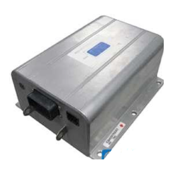
Page 9: Outline: Sx-2 Package Size
OUTLINE DRAWINGS, ELEMENTARY DRAWINGS AND INPUTS/OUTPUTS SX TRANSISTOR CONTROL Page 9 Section 3.2 Outline: SX-2 Package Size April 2002... -
Page 10: Standard Elementary For Nev Application
ELEMENTARY DRAWING FOR TYPICAL SEPARATELY EXCITED TRACTION MOTOR CONTROLLER FOR NEV APPLICATIONS FU3 * CHARGER SWITCH * KEY SWITCH * DIRECTIONAL FU1 * LINE * SWITCH * 400A P2 P3 P21 P11 P10 PLUG (23 PIN) +12V P15 P14 P7 P9 P13 P8 P6 POWER CONNECTIONS TO CONTROL... -
Page 11: Standard Nev Application Input/Output List
OUTLINE DRAWINGS, ELEMENTARY DRAWINGS AND INPUTS/OUTPUTS SX TRANSISTOR CONTROL Page 11 Section 3.4 Standard Neighborhood Electric Vehicle Application Input/Output List Connections to Main Plug (23 Pin) and “Y” Plug (8 Pin) MAIN PLUG INPUT/OUTPUT DESCRIPTION BATTERY VOLTS FROM BATTERY BATTERY VOLTS FROM KEY 12 VOLT INPUT FROM ACCELERATOR START SWITCH 12 VOLT INPUT FROM FORWARD SWITCH 12V VOLT INPUT FROM REVERSE SWITCH... -
Page 12: Troubleshooting And Diagnostic Status Codes
The semiconductor junctions have finite temperature limits, above which these devices GE does not recommend that any type of welding be may be damaged. For these reasons, normal maintenance performed on the vehicle after the installation of the should guard against any action which will expose the control(s) in the vehicle. -
Page 13: High Level Signals (Level H)
DIAGNOSTIC STATUS CODES SX TRANSISTOR CONTROL Page 13 •= Control common tie customer must apply the general guidelines (section •= DC buses feeding sensitive analog or digital hardware 4.2.3.a), outlined below. •= All wiring connected to components associated with 4.2.3.a General Cable Spacing sensitive analog hardware with less than 5V signals (for example, potentiometers and tachometers) •= Digital tachometers and resolvers... -
Page 14: Recommended Lubrication Of Pins And Sockets Prior To Installation
EV100/EV200 and Gen II products. Any connection made by Clean each terminal using Chemtronics contact GE to the A, B, X, Y, or Z plugs, includes the lubricant NYE cleaner “Pow-R-WasH CZ “ as shown in Figure 1. 760G to prevent fretting of these connections during vehicle operation. -
Page 15: General Troubleshooting Instructions
DIAGNOSTIC STATUS CODES SX TRANSISTOR CONTROL Page 15 Section 4.4 General Troubleshooting Instructions Trouble-shooting the ZX family of controls should be quick and easy when following the instructions outlined in the following status code instruction sheets. If mis-operation of the vehicle occurs, a status code will be displayed on the Dash Display (for vehicles equipped with a Dash Display) or made available by plugging a Handset into the plug "Y"... -
Page 16: Traction Controller Status Codes
DIAGNOSTIC STATUS CODES SX TRANSISTOR CONTROL Page 16 Section 4.5 Traction Control Codes TRACTION DESCRIPTION OF STATUS CAUSE OF STATUS INDICATION STATUS CODE Segments do not illuminate on the No input voltage to the control card or the display unit. NONE Dash Display and/or the Handset. - Page 17 DIAGNOSTIC STATUS CODES SX TRANSISTOR CONTROL Page 17 TRACTION DESCRIPTION OF STATUS CAUSE OF STATUS INDICATION STATUS CODE The accelerator pedal is depressed with This status code will be displayed when the no direction selected. accelerator voltage, at P7>1.5V, and no direction is selected (P4 and P5 are both less than 7.2V) MEMORY RECALL CORRECTIVE ACTIONS...
- Page 18 DIAGNOSTIC STATUS CODES SX TRANSISTOR CONTROL Page 18 TRACTION DESCRIPTION OF STATUS CAUSE OF STATUS INDICATION STATUS CODE Both the forward and reverse switches This status code will be displayed when P4 and P5 are closed at the same time. are less than 7.2 volts, and P7 is less than 2.5 volts.
- Page 19 DIAGNOSTIC STATUS CODES SX TRANSISTOR CONTROL Page 19 TRACTION DESCRIPTION OF STATUS CAUSE OF STATUS INDICATION STATUS CODE Battery voltage is too low at initial key switch This status code will be displayed when the closure. battery volts are less than 68.3 volts at initial key switch on.
- Page 20 DIAGNOSTIC STATUS CODES SX TRANSISTOR CONTROL Page 20 TRACTION DESCRIPTION OF STATUS CAUSE OF STATUS INDICATION STATUS CODE Accelerator voltage is too high. This status code will be displayed when the accelerator voltage at P7 is greater than 4.5 volts. MEMORY RECALL CORRECTIVE ACTIONS TROUBLE-SHOOTING DIAGRAM...
- Page 21 DIAGNOSTIC STATUS CODES SX TRANSISTOR CONTROL Page 21 TRACTION DESCRIPTION OF STATUS CAUSE OF STATUS INDICATION STATUS CODE Motor field current is too high on when This status code will be displayed when the current the start switch is closed and the draw in the motor field is too high on start up in the forward direction is selected.
- Page 22 (Values of greater than 4 V at the thermal protector are typically indicative of a failed control.) GE Sentry for Windows software can be used to monitor control operation, and it will display a value for the thermal protector that is greater than 84 (corresponding to 1.65V), triggering this...
- Page 23 Traction •= Replace controller unit. Controller GE Sentry for Windows software can be used to monitor control operation, and it will display a value for the motor amps that is less than 117 (corresponding to 2.3V), triggering this status code.
- Page 24 DIAGNOSTIC STATUS CODES SX TRANSISTOR CONTROL Page 24 TRACTION DESCRIPTION OF STATUS CAUSE OF STATUS INDICATION STATUS CODE Armature transistor did not turn on This status code will be displayed when, during properly. control operation, the armature transistor fails to turn on properly.
- Page 25 DIAGNOSTIC STATUS CODES SX TRANSISTOR CONTROL Page 25 TRACTION DESCRIPTION OF STATUS CAUSE OF STATUS INDICATION STATUS CODE Motor field current is too low during the This status code will be displayed when the current run mode. draw in the motor field is less than 1.3 amps and armature current is greater than 100 amps for more than 1.27 seconds during the run mode.
- Page 26 DIAGNOSTIC STATUS CODES SX TRANSISTOR CONTROL Page 26 TRACTION DESCRIPTION OF STATUS CAUSE OF STATUS INDICATION STATUS CODE Controller “motor current sensor” input This status code will be displayed when the voltage is too low during running. input from the current sensor is too low (less than 1.43V, -350 amps) during running.
- Page 27 DIAGNOSTIC STATUS CODES SX TRANSISTOR CONTROL Page 27 TRACTION DESCRIPTION OF STATUS CAUSE OF STATUS INDICATION STATUS CODE Capacitor (1C) voltage too high during This status code will be displayed when the voltage at regenerative braking. 1C exceeds 96 volts during the regenerative braking cycle.
- Page 28 DIAGNOSTIC STATUS CODES SX TRANSISTOR CONTROL Page 28 TRACTION DESCRIPTION OF STATUS CAUSE OF STATUS INDICATION STATUS CODE Motor thermostat is open during control This status code will be displayed when the voltage at operation. P21<5.66V for at least 30 seconds. MEMORY RECALL CORRECTIVE ACTIONS TROUBLE-SHOOTING DIAGRAM...
-
Page 29: Sx Family - Ge Handset Instructions
START-UP DISPLAY SEQUENCE Section 5.1 General Features Key Switch On The GE Handset is a multi-functional tool to be used with the LX, ZX, and SX Series GE solid-state controls. The Handset consists of a Light Emitting Diode (LED) display Verify Each LED Segment and a keyboard for data entry. -
Page 30: Setup Function Procedures
This will place you in the setup mode, ready to monitor or adjust control function settings. ACCESSING STORED STATUS CODES NOTE: The term “Push” means to depress key for WITH GE HANDSET approximately one second. Key Switch Off Section 5.3.1 Setup Mode... -
Page 31: Setup Functions For Traction Controller
Important Note: The function is used to optimize motor and control performance and this setting will be determined by GE and OEM engineers at the time of vehicle development. This setting must not be changed by field personnel without the permission of the OEM. - Page 32 GE and OEM engineers at the time of vehicle development. GE and OEM engineers at the time of vehicle development. This setting must not be changed by field personnel without This setting must not be changed by field personnel without the permission of the OEM.
- Page 33 ADJUSTABLE FEATURES SX TRANSISTOR CONTROLS Page 33 FUNCTION 12 REVERSE SPEED LIMIT INTERNAL RESISTANCE COMPENSATION ( Push 12 ) TABLE This function allows for the adjustment of the top speed of Setting Setting Drop Drop the vehicle (maximum battery volts to the motor) when it is 11.44 1.34 being operated in the reverse direction.
- Page 34 Important Note: The function is used to optimize motor and DELAY control performance and this setting will be determined by GE and OEM engineers at the time of vehicle development. ( Push CONT 3 ) This setting must not be changed by field personnel without the permission of the OEM.
- Page 35 ADJUSTABLE FEATURES SX TRANSISTOR CONTROLS Page 35 ( Push CONT 11) 0 to 99 Example 9999 Hours This function sets the ratio between armature and field current when transitioning from minimum field to maximum field current. The setting represents the quantity of field FUNCTION 30 HOUR METER THOUSANDS current changed for each 1 amp of armature current...
-
Page 36: Summary Of Current Limit Adjustments
The value for this function will be defined by the GE application engineer. The " minimum field current" setting is adjusted by Function 7. The function sets the top speed of the motor. -
Page 37: Memory Map
Error Compensation HS or PC None Field Weakening Start HS or PC None Monitor HS or PC GE Temporary Storage Ratio of Field to Armature Amps HS or PC None Hour Meter Minutes HS or PC None Fault Count Pointer... - Page 38 RS-232 MEMORY MAP TABLES SX TRANSISTOR CONTROL Page 38 Func No. Traction Control Access By Restrictions Function BDI 4 PC Only Reset to Zero Only Hours (Tens/Ones) 4 PC Only Reset to Zero Only Hours (Thou/Hun) 4 PC Only Reset to Zero Only (26) Stored Status Code #5 PC Only...
- Page 39 Secure Aux HM (Tens/Ones) PC Only OEM Read Only Secure Aux HM (Thou/Hun) PC Only OEM Read Only Field Offset PC Only GE Future Use Field Offset PC Only GE Future Use Armature Offset PC Only GE Future Use Reserved...