Table of Contents
Advertisement
Quick Links
OPERATION & MAINTENANCE MANUAL FOR 400kV CIRCUIT BREAKER
Owner
Project
Consultant
Document
O & M Manual
Type
(Information Only)
Document
400kV Circuit
Name
Breaker - Manual
Copyright© Siemens Ltd 2007.
The reproduction, transmission or use of this document or its contents is not permitted without express written au-
thority. Offenders will be liable for damages. All rights, including rights created by patent grant or registration of a
utility model or design, are reserved.
DOC. No. - SIEM-JITPL.5404A-EL-3-2112
Project
JINDAL INDIA THERMAL POWER LIMITED
(2 x 600 MW THERMAL POWER PROJECT)
OPERATION & MAINTENANCE
MANUAL FOR
400kV CIRCUIT BREAKER
JINDAL INDIA THERMAL POWER LIMITED
2 x 600 MW THERMAL POWER PROJECT
TATA CONSULTING ENGINEERS
Document Number
SIEM-JITPL.5404A-EL-3-2112
400kV Circuit Breaker
JINDAL INDIA THERMAL POWER LIMITED
(2 x 600MW THERMAL POWER PROJECT)
Date
23.06.2011
Consultant
O&M
TATA CONSULTING ENGINEERS
Siemens Limited,
Aurangabad.
Page 1 of 109
Advertisement
Table of Contents

Related Manuals for Siemens 3AP2-FI


Summary of Contents for Siemens 3AP2-FI
- Page 1 Name Breaker - Manual Copyright© Siemens Ltd 2007. The reproduction, transmission or use of this document or its contents is not permitted without express written au- thority. Offenders will be liable for damages. All rights, including rights created by patent grant or registration of a utility model or design, are reserved.
- Page 2 Operating Instructions Circuit-Breaker 3AP2 Fl for rated voltage 420 kV 1003006a Siemens Ltd. © Siemens Ltd 2007...
- Page 3 The Siemens Ltd, Power Transmission and Distribution Group, High Voltage Division has introduced and appiies a quality system in accordance with EN ISO 9001. If you require further copies of the operating instructions, please order them from the appropriate Siemens office, indicating the title and order number: Published by: Siemens Ltd.
-
Page 4: Table Of Contents
1 Contents Contents General Introduction 2.1.1 Arrangement of the Operating Instructions 2.1.2 Communication by Means of the Operating Instructions Safety Instructions Description Technical Data 3.1.1 Standards, Regulations 3.1.2 Operating Temperatures 3.1.3 Insulation Rating 3.1.4 Electrical Data 3.1.5 Operating Times 3.1.6 Arc Quenching Medium SF 3.1.7 Auxiliary Switch... - Page 5 1 Contents Installation Safety Rules for Installation Delivery and Storage 4.2.1 Packing 4.2.2 Checking on Arrival 4.2.3 Storage Cleaning Liquids, Lubricants and Corrosion Protection Agents 4.3.1 Cleaning Liquids 4.3.2 Lubricants and Corrosion Protection Agents General Instructions for Installation Installation of the Circuit-Breaker 4.5.1 Requirements for Assembly 4.5.2...
- Page 6 1211 1 Contents 5.1.4 Mechanical Reclosing Lockout 5.1.5 Max. Permissible Number of Interruptions 5.1.6 Recommended Procedure in the Event of Irregularities on the Circuit-Breaker 3AP2 Fl Disposing of High-Voltage Switching Devices and Systems Maintenance Inspection and Maintenance - General 6.1.1 Maintenance Services (Schedule) 6.1.2 Assignment of Personnel...
-
Page 7: General
Should further information be desired or should particular problems arise which are not covered sufficiently in the operating instructions, the matter should be referred to the local Siemens sales office. 2.1.1... -
Page 8: Safety Instructions
Note Note in the sense of these operating instructions means information to simplify and improve the handling of the circuit-breaker. They are based on the experiences of Siemens staff. -
Page 9: Description
3 Description Description Technical Data The 3AP2 Fl circuit-breaker is of the self-compression type and uses SF -gas for insulation and arc-quench- ing purposes. It is of triple-pole outdoor design. The circuit-breaker is equipped with one operating mechanism per pole and therefore suitable for single and triple pole auto reclosing. -
Page 10: Insulation Rating
3 Description 3.1.3 Insulation Rating Rated voltage 420 kV Rated short-duration power-frequency withstand voltage to earth 520 kV across the open circuit-breaker 610 kV between phases 520 kV Rated lightning impulse withstand voltage to earth 1425 kV across the open circuit-breaker 1425 kV between phases 1425 kV... -
Page 11: Operating Times
3 Description 3.1.5 Operating Times 80 ms Minimum command duration (Closing com- mand) 80 ms Minimum command duration (Opening command) Closing time 65 ms + 6 ms Opening time 23 ms + 3 ms Rated break time <40 ms Close-open-time 60 ms + 10 ms Dead time 300 ms... -
Page 12: Arc Quenching Medium Sf
3 Description 3.1.6 Arc Quenching Medium SF -filling gauge pressure (nominal density line) Signal Loss of SF General lockout SF Liquefaction curve Fig. 1 -filling and operating values of density monitor (gauge pressure) Filling weight (complete circuit-breaker) 44.6 kg Volume (complete circuit-breaker) 966 dm3 nominal filling gauge pressure at +20°C 6.0 bar... -
Page 13: Anti-Condensation Heaters
3 Description 3.1.8 Anti-Condensation Heaters Control cubicle 90 W Operating mechanism 210 W Table 6 Anti-condensation heaters The anti-condensation heaters must always be switched on. 3.1.9 Reference Contact IK-3 Principle Fixed Hall sensor and moving magnet Hall sensor HE-6103 Magnet HE-6104 Supply voltage 24VDC... -
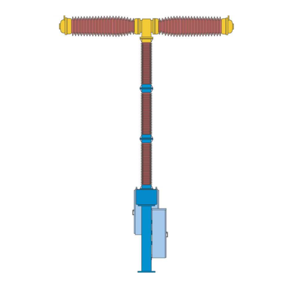
Page 14: Circuit-Breaker
3 Description Circuit-Breaker The pole columns of the circuit-breaker are each mounted on a base 11, to the side of each of which an operating mechanism cubicle 15.1 is fitted. The insulator columns are assembled from several multished insulators and each of them supports an double break interrupter assembly consisting of two interrupter units 22 with grading capacitors 23 connected in parallel and a bell-crank mechanism 21. - Page 15 3 Description The two interrupter units provide a double-break feature per pole, the grading capacitors ensuring uniform voltage distribution. The double break assembly and the insulator column are filled with SF for arc-quenching and insulating purposes. The density of the SF gas for each circuit-breaker pole is monitored by a density monitor and the gas pressure indicated by a manometer.
-
Page 16: Pole Column
3 Description Pole Column The circuit-breaker's three pole columns are of identical design. Fig. 3 shows a cross-section of a pole column. The double break assembly unit is mounted on post insulators which provide insulation against earth. 15.16.3 22.22 15.11 15.9 15.8.3 Corner gear... - Page 17 3 Description The switching operation is transmitted to the interrupter units 22 (high-voltage potential) by the spring drive mechanism (ground potential) via an operating mechanism rod 18.27.1, the shaft 15.8.3, the operating rod 16.9 and the bell-crenk mechanism 21. The filter cowls 15.11 contains the filter material 15.16.3 which collects SF decompositon products and moisture residue.
-
Page 18: 3.4 Interrupter Unit
3 Description 3.4 Interrupter Unit Fig. 5 shows a sectional view of an interrupter unit. The breaker contacts are accommodated in the gas-tight porcelain jacket 22.1. 15.11 Filter cowl 16.9 Operating rod 21.1 Gear unit housing 22.1 Jacket 22.11 Tube contact 22.11.1 Nozzle 22.11.17... - Page 19 3 Description Parallel to the main circuit is the arcing circuit, which is made up of the movable pin 22.9 in the contact carrier 22.31 and the moving tube contact 22.11 situated in the heating cylinder 22.41. The pin 22.9 and the tube contact 22.11 are made of materials which produce only minimal contact erosion. The tube contact 22.11, the piston 22.11.17 and the heat cylinder 22.41 are mechanically interconnected and coupled with the pull rod 22.17.1.
-
Page 20: Arc Quenching
3 Description Arc Quenching In an opening operation, the main contact that exists between the contact laminations 22.3 and the heat cylinder 22.41 is opened (Fig. 6, position b). The arcing contact, consisting of the pin 22.9 and the tube contact 22.11 remains closed, with the result that the current commutates onto the arcing contact. - Page 21 3 Description The pin (moving) 22.9 is moved against the direction of movement of the tube contact 22.11 by the connected components of heating cylinder 22.41, nozzle 22.11.1, connecting rod 22.51, pin 22.52, control lever 22.46 (circuit-breaker opening movement). The moved electrode 22.45 is also pushed in the direction of the heating cylinder 22.41. During the continued course of the opening operation, the arcing contact opens, creating an arc (Fig.
-
Page 22: Spring Drive Mechanism Of The Circuit-Breaker
3 Description Spring Drive Mechanism of the Circuit-Breaker This section contains a general presentation of the spring drive mechanism; see the 3D illustration on the foldout page at the end of these operating instructions. Its function is described in section 3.7 Function of the Spring Drive Mechanism. -
Page 23: Opening
3 Description 3.6.3 Opening Actuating tripping coil 18.8 releases OPEN latch 18.9. The contacts of interrupter unit 22 are separated by opening spring 18.11 via connecting rod 18.27, operating lever 18.24, operating mechanism rod 18.27.1, lever 15.9, torque shaft 15.8.3 and operating rod 16.9. The kinetic energy at the end of the opening cycle will thereby be absorbed by opening damper 18.15. -
Page 24: Function Of The Spring Drive Mechanism
3 Description Function of the Spring Drive Mechanism The function of the spring drive mechanism is described below in conjunction with the major modular assemblies. It is advisable first to read the section 3.6 Spring Drive Mechanism of the Circuit-Breaker. 3.7.1 Charging the Closing Spring Starting position: the circuit-breaker is in the OPEN position. - Page 25 3 Description 18.10 Connecting rod (for closing spring) 18.11 Opening spring 18.14 Charging shaft 18.15 Damper for opening 18.16 Release CLOSE 18.17 Closing latch 18.17.1 Support lever 18.19 18.22 Operating shaft 18.23 Roller 18.24 Operating lever 18.27 Connecting rod (for opening spring) 18.27.1 Driving rod 18.31...
- Page 26 3 Description 18.20 18.14 18.2 18.3 18.1 1000661a 18.1 Motor 18.14 Charging shaft 18.2 Charging gear 18.20 18.3 Free-wheel Fig. 8 Function of the free-wheel: Charging of the closing spring 18.4 1000810a 18.14 Charging shaft 18.17 Closing latch 18.23 Roller 18.31 Mechanical closing interlock 18.4...
-
Page 27: Closing
3 Description 18.14 Charging shaft 18.2 Charging gear 18.20 18.3 Free-wheel Fig. 10 Function of the free-wheel: Uncoupling the charging gear 3.7.2 Closing Actuating CLOSE tripping coil 18.16 releases cam disk 18.6 via CLOSE latch 18.17 and supporting lever 18.17.1 (Fig. - Page 28 3 Description The effect of the closing spring turns the charging shaft 18.14 (Fig. 12). The roller 18.7.1 of the lever 18.7 moves along the cam 18.6 and transmits the movement to the operating shaft 18.22. The movement is then transmitted by the lever 18.24 (fixed to the operating shaft 18.22) and the operating mechanism rod 18.27.1 to the interrupter unit 22.
- Page 29 3 Description At the same time the opening spring 18.11 is charged by way of the operating lever 18.24 and the connecting rod 18.27. The opening latch 18.9 moves along the roller of the latch lever 18.9.1 (Fig. 12). At the end of the curve, the lever 18.7 overtravels, with the result that the opening latch 18.9 can drop behind the roller of the latch lever 18.9.1 (Fig.
- Page 30 3 Description On completion of the closing cycle, cam 18.19 will run on roller 18.141.1 and transfer its residual kinetic energy to damper for closing 18.41 (Fig. 13). Following this, roller 18.41.1 will jump behind cam 18.19 to prevent backward swinging of charging shaft 18.14 (Fig.
- Page 31 3 Description 18.14 Charging shaft 18.15 Damper for opening 18.17 Closing latch 18.17.1 Support lever 18.31 Mechanical closing interlock 18.4 Closing spring Fig. 15 Function diagram of closing and opening latching: Latching of the charged closing spring As the closing process takes place, the charging motor is switched on. The charging of the closing spring is repeated according to paragraph 3.7.1 Charging the Closing Spring.
-
Page 32: Tripping
3 Description 3.7.3 Tripping Actuating OPEN trip coil 18.8 releases OPEN latch 18.9 via supporting latch 18.9.1 and supporting lever 18.9.2. Operating lever 18.24 and lever 18.7 are withdrawn by opening spring 18.11 over connecting rod 18.27 to the OPEN position (Fig. 16). The contacts of interrupter unit 22 are simultaneously shifted to the OPEN position over operating mechanism rod 18.27.1. -
Page 33: Control
3 Description Control The control system includes all secondary technical components necessary for the operation of the circuit- breaker, which are for the main part located inside the control cubicle and the housing of the operating mech- anism. The documentation for the circuit-breaker includes the circuit diagram of the control system. This diagram contains the following documents: Location diagram Schematic diagram... -
Page 34: Spring Winding Mechanism
3 Description Note The operator is responsible for the fuse protection for the auxiliary circuits, unless otherwise agreed with the manufacturer. 3.8.1 Spring Winding Mechanism The spring winding mechanism consists of the motor and the charging gear. The spring state indicators (symbols) are on the spring cups and will be shown by intelligible symbols. - Page 35 3 Description density monitor Pressure gauge Filling flange Test connection Fig. 19 Diagram of SF monitoring in a pole column The density of the SF arc quenching material in the gas compartment is monitored by a density monitor B4 (Fig. 21).
- Page 36 3 Description 1001305a Density monitor Test connection Fig. 21 Test connection W2 (view with cover of the contact position indicator removed) 3.8.2.1 Function of the Density Monitor The density monitor compares the density of the SF gas in the compartment to be monitored with the density of reference gas enclosed inside the monitor.
-
Page 37: Lockouts
3 Description 5.00 Bellows 5.10 Microswitch 5.20 Housing 5.30 Circuit-breaker gas compartment 5.40 Reference gas compartment Fig. 22 Schematic diagram of the density monitor (under working pressure) 3.8.3 Lockouts The individual functions are explained in the order of their appearance in the circuit diagram. A General lockout SF prevents any switching of the circuit-breaker if the SF pressure is too low. -
Page 38: Free Auxiliary Switch Contacts
3 Description 3.8.7 Free Auxiliary Switch Contacts Additional free auxiliary switch contacts at the terminal fixture X1 are available for customer's purposes. 3.8.8 Operating Cycle Counter The circuit-breaker is equipped with one counter per pole (Fig. 17). It counts the number of switching operations performed. -
Page 39: Reference Contact
3 Description Reference Contact IK-3 3.9.1 Introduction Attention The warnings in the operating instructions for high-voltage circuit-breakers must be observed! Work may only be performed at the reference contact in the OPEN position with the closing and opening springs relaxed. Discharge the closing and opening springs: Disconnect motor power supply, Open circuit-breaker (from closed position),... - Page 40 3 Description Edge to be evaluated at CLOSE Edge to be evaluated at OPEN Fig. 24 Output signal of the IK-3 The IK-3 is designed as a two-wire system in which the output signal is transmitted by a current loop. Sensor electronics Sensor HE-6103 Magnet HE-6104...
-
Page 41: Installation
4 Installation Installation Safety Rules for Installation WARNING Danger to installation personnel can result from - hazardous voltage - SF -gas - falling and/or toppling parts and/or moving parts. Non-observance of warnings can result in death, severe personal injury and substantial property and environmental damage. - Page 42 4 Installation The safety regulations in these operating instructions are minimum requirements. They do not affect statutory laws, standards, specifications or internal regulations of the company concerned with the work. They do not claim to cover all eventualities and must be expressed concretely by the responsible persons at the latest before work actually starts.
- Page 43 4 Installation WARNING is heavier than air. In closed areas it may displace the air - Danger of suffocation! Use a service unit for all work with SF gas. Extract the SF filling; do not let it escape into the air.
-
Page 44: Delivery And Storage
4 Installation Delivery and Storage Attention Avoid damaging the porcelain bodies. 4.2.1 Packing The circuit-breaker is supplied as pretested modular assembly. If transported by land, the components are delivered in crates. If transported by container (by sea), some are supplied on pallets and some in crates. All components and parts required for commissioning and operation are included in the shipment in a separate package. - Page 45 4 Installation After one year's storage, the external surfaces treated with Tectyl 506 should be given a thick second coating. Before storing the accessory items, check their plastic wrapping for signs of damage. If the plastic foil has sus- tained damage, unpack the parts and store them in a dry, ventilated room.
-
Page 46: Cleaning Liquids, Lubricants And Corrosion Protection Agents
4 Installation Cleaning Liquids, Lubricants and Corrosion Protection Agents 4.3.1 Cleaning Liquids For cleaning and degreasing metal parts and sealing rings use any of the following (not included in the scope of supply). Attention Improper handling can result in personal injury, fire and environmental damage. In the interest of safety, follow instructions for use of cleaning liquids carefully. -
Page 47: Lubricants And Corrosion Protection Agents
4 Installation 4.3.2 Lubricants and Corrosion Protection Agents The following lubricants and corrosion protecting agents are required for installation and maintenance of the circuit-breakers: Kliiber grease Centoplex 24 DL for all lubricating points and non-hot-galvanized screws, unless another brand of lubricant is specified. Isoflex Topas L32 for radial sealing rings and rolling contact bearings of the SF shaft seal on the corner gear and on the operating... -
Page 48: General Instructions For Installation
4 Installation General Instructions for Installation For assembling the circuit-breaker use only the bolts supplied. Spare bolts are included in the accessories pack, in case any are lost during assembly work. WARNING If unsuitable bolts are used, they can malfunction and cause severe personal injury. If the number of bolts supplied for the pressure vessels is insufficient, spare bolts must be ordered from the factory only. -
Page 49: Installation Of The Circuit-Breaker
4 Installation Installation of the Circuit-Breaker WARNING The control leads must not be connected to the terminal block of the operating mechanism until the circuit-breaker has been erected complete with the pole columns. 4.5.1 Requirements for Assembly You will require the following equipment and tools for next work steps in the assembly of the circuit-breaker: A crane with suitable suspension tackle Evacuating equipment P= 20 mbar... -
Page 50: Assembly Overview
4 Installation 4.5.3 Assembly Overview Fig. 26 Assembly overview Note Discard all screws and nuts marked red! 4.5.4 Disassembling the Insulator Column Kit Loosen the M16 nuts at the fixing point between the bracket 1.3 and the wooden beams 1.6. Lift the three insulator columns in the kit with the crane and put them down onto the brackets 1.3 on a solid base but do not disconnect the suspension tackle fom the insulator column kit. - Page 51 4 Installation Packaging cap for insulator column Bracket Connecting plate Lifting eye plate Wooden beam Lifting eye-bolt Fig. 27 Insulator column kit Disassemble the insulator column kit as shown in Fig. 27 starting at the bottom and put the individual columns down on a solid base.
- Page 52 4 Installation BM 16x55 BM 16x55 BM 16x55 The M16x55 screw is not replaced. Fig. 29 Screw distribution for insulator column assembly. The screws are then tightened to 170 Nm.
-
Page 53: Assembly Of The Control Cubicle
4 Installation 4.5.5 Assembly of the Control Cubicle Control cubicle 15.1 Operating mechanism Fig. 30 Control cubicle/operating mechanism transport unit Insert the crane hook into the lifting eye-bolts of the control cubicle and undo screw joints to the other components of the transport unit. -
Page 54: Assembly Of The Operating Mechanism Cubicles
4 Installation 11.13 Pillar Control cubicle Fig. 31 Assemble control cubicle at pillar 4.5.6 Assembly of the Operating Mechanism Cubicles The doors of the operating mechanism cubicles are labelled LA, LB and LC. The operating mechanism cubicles are assembled on the pillars for poles A, B and C according to this labelling. This allocation of operating mechanism to poles must be strictly observed because of the coded pole connecting cables. -
Page 55: Assembling The Insulator Column
Pillar Flange Plate Breaker base Fig. 32 Operating mechanism cabinet with base mounted on pillar 4.5.7 Assembling the Insulator Column The circuit-breaker poles are labelled LA, LB and LC on the double interrupter heads, the insulator columns and the lower part of the circuit-breaker. Make sure the double interrupter heads and insulator columns are assigned correctly to the circuit-breaker poles and check the last four digits in the serial number on the lower part of the circuit-breaker when you install the circuit-breaker. - Page 56 4 Installation Packaging cap Lifting eye-bolt Fig. 33 Packaging cap for insulator column Attention The time between removing the transport cover and evacuation of the circuit-breaker pole must not exceed one hour. Attention During assembly work, the open insulator column should be protected against atmospheric influences using suitable covers.
- Page 57 4 Installation Wood Connecting plate Lower lifting eye plate Comer gear 15.9.01 Lever Upper lifting eye plate Fig. 34 Installing insulator columns (diagram shows the top insulator column in the kit) Loosen and remove the 2 lifting eye plates 1.5. Before you raise the insulator column place a wooden base under the corner gear.
- Page 58 Then align the insulator column so that pegging out with the bolt 10.9 (Fig. 49) is possible. Now tighten the four M 16x65 screws to a torque of 170 Nm. Tighten the four M8x40 screws and nuts with a torque of20Nm. 15.16.3 16.7 1002226a...
-
Page 59: Erecting The Double-Break Assembly
(Fig. 39). The relative humidity in % is above this figure, but still below the next higher figure. Note The humidity value reading may not exceed 40 %. If the humidity value is above this, inform the nearest Siemens representative! - Page 60 4 Installation Fig. 39 Humidity indicator The old desiccant agent is removed and disposed of. Treatment of the sealing flanges and the guide The sealing faces of the flanges and the guide must be treated carefully since even minor damage may lead to leaking joints.
- Page 61 4 Installation Move the lever to CLOSED position (the drive rod moves upwards) and lock it to the base using the rubber retaining ring supplied so that ir remains in CLOSED position. Position a lubricated O-ring on the upper flange of the post insulator column. Remove the transport protection 1, which is used only during transport (Fig.
- Page 62 4 Installation W350 Spacer 16.6 Centering guide 16.7 Sealing ring 16.9.1 Yoke head Fig. 42 Install spacer Lift double interrupter head to eye level with crane on the lifting plates (Fig. 47). Lifting plate Fig. 43 Lifting plate arrangement Attention The double interupter head must be suspended horizontally for assembly.
- Page 63 4 Installation Remove the transport cover 21.9.9 (Fig. 45) from the double interrupter head and take out the desiccant bags. Prepare the sealing flanges as described above. Remove the cable binder used as transport protection. Bring the interrupter unit into OPEN position by pulling the two coupling levers jerkily as far as they will go.
- Page 64 4 Installation W350 Spacer 16.6 Centering guide 16.7 Sealing ring 21.11 SL-Safety clip 21.7 Coupling lever 21.7.3 Coupling bolt Fig. 45 Erecting the double-break assembly...
-
Page 65: Lifting Plate
4 Installation W350 Spacer 16.3 Post insulator 16.6 Centering guide 16.6.1 Teflon strip 16.7 Sealing ring 16.9 Operating rod 16.9.1 Yoke head 21.1 Housing 21.7 Coupling lever 21.7.3 Bolt Fig. 46 Centering guide and coupters fitted Attention Hold the double-break assembly by means of the crane; do not lift it! Remove the three spacers. -
Page 66: Coupling The Operating Mechanism
4 Installation Lifting plate Interrupter unit Fig. 47 Lifting plate arrangement 4.5.10 Coupling the Operating Mechanism Using the manual actuator supplied, the lever 15.9 is moved in such a way that it can be connected to the bolt 10.9. The bolt remains in operating position. W387 Manual operating device W387 15.9... -
Page 67: Connecting The Gas Pipes
4 Installation 15.9 10.1 10.9 18.27.1 10.1 10.9 Marking position Operation position 10.1 Bolt with lock washer 10.9 Bolt 15.9 Lever 18.27.1 Driving rod Fig. 49 Coupling the operating mechanism Set up the two other poles in the same way replacing the original screws after removal of the lifting eye-bolts. Next pull the bolt 10.9 out at all three poles (Fig. - Page 68 4 Installation To connect the gas pipes 51.1 to the flanges 15.40 of the pole columns, remove the union nuts 15.40.1 with sealing cap (Fig. 50) from the flanges 15.40 and make the connections as shown in Fig. 51. First of all align the gas tube flange 51.1 parallel to the surface of the flange 15.40 on the corner gear and insert a new O-ring 15.40.3 which has been lubricated with Vaseline.
-
Page 69: Earthing And Connecting The Leads
4 Installation Earthing and Connecting the Leads 4.6.1 Earthing Connect the breaker base to the high-voltage station earth by means of earth terminals provided. Earthing bolts Fig. 52 Earthing bolts in base (viewed from outside/inside) 4.6.2 Work on High-Voltage Terminals WARNING For safety reasons, work on high-voltage terminals should be carried out before the circuit- breaker is filled with SF... -
Page 70: Connecting The Leads
4 Installation Connecting the high-voltage conductors Brush the contact surfaces of the high-voltage terminals with a steel wire brush, which has only been used for aluminium, until they are bright and slightly roughened. Wipe the contact surfaces off with lint-free paper or cloth and lightly coat them with acid-free Vaseline, e.g. -
Page 71: Filling The Circuit-Breaker With Gas
3.1.6 Arc Quenching Medium SF 4.7.2 Filling the Breaker from the Gas Cylinder Siemens offers a complete filling device of type W423 for filling the circuit-breaker with SF gas from a gas cylinder (Fig. 53). Attention... - Page 72 4 Installation WARNING High gas pressure - Danger of bursting! Exceeding the permissible filling pressure can cause the pole columns to burst, resulting in severe personal injury and damage to property. The filling device must include a safety valve (operating pressure 8.0 bar). The safety valve prevents the pressure compartments from being overstressed due to an impermissibly high pressure.
-
Page 73: Leakage Test After Installation
Filling flange Gas cylinder Pressure reducer regulating valve Precision pressure gauge (-1.0 bar up to 9.0 bar) Safety valve Fig. 55 Gas filling device connected At an ambient temperature other than +20°C, the SF filling pressure must be taken from the diagram (Fig. 1). The filling pressure may be up to 0.30 bar over the nominal pressure curve (temperature-independent). -
Page 74: Carrying Out Test Operations
4 Installation Carrying Out Test Operations When installation work is finished, the circuit-breaker is in the OPEN position. The closing spring of the operating mechanism is not charged. See section 3.7 Function of the Spring Drive Mechanism When the motor control power supplies are switched on, the charging motors automatically start up and stop again when the closing spring has been charged and latched. - Page 75 4 Installation WARNING Danger of serious mechanical damage! Mechanical test operations must only be performed with sufficient SF gas filling: Pressure must at least be at the level of general lockout SF , see Table 4. When installation work is finished, 5 test switching operations should be carried out per circuit-breaker pole. With regard to the possibility of the porcelain components having suffered transport damage, these mechanical switching operations must be performed by remote control as safety switching operations.
-
Page 76: Checks Before Commissioning
4.9.3 Commissioning Report It should be checked that the commissioning report enclosed with the circuit-breaker has been completed in full and signed. Please return it to the manufacturer at the following address: Siemens Ltd. PTD-Division E-76. Waluj MIDC Aurangabad 431136... -
Page 77: Operation
5 Operation Operation Instructions for Operation 5.1.1 Closing and Opening WARNING Danger of serious mechanical damage! An SF -minimum gas pressure (SF -blocking pressure) must be available for test operations (without current and voltage). WARNING Danger! - High voltage! A circuit-breaker connected to high voltage may only be operated conforming with the safety regulations of the facility. -
Page 78: General Lockout
-pressure before working on the screw connections of the gas chamber. If the above signal is initiated again after some time, the leak must be located and, if possible, sealed. If the leak cannot be sealed, the nearest Siemens representative should be notified. 5.1.3... - Page 79 5 Operation Breaking current in kA Weighting factor Max. permissible number of interruptions During the type tests 10000 mechanical operation cycles were carried out. Fig. 57 Max. permissible number of interruptions as a function of the breaking current. The chart (Fig. 57) relates to one pole of a triple-pole circuit-breaker. Three times the number of the permissible single-pole opening operations may thus result in a triple-pole circuit-breaker (e.g.
- Page 80 5 Operation 6000 - Σ (n i • i = 1 1000037b Weighting factor for breaking current I Weighting factor for breaking current l Number of carried out interruptions at breaking current I Number of remaining permissible interruptions at breaking current l Fig.
-
Page 81: Recommended Procedure In The Event Of Irregularities On The Circuit-Breaker
The following table is an aid in recognition and assessment of any irregularities occuring in operation of the circuit-breaker. It also enables specific details to be given if Siemens service Berlin personnel have to be summoned. In such a case, please telephone during business hours Tel.: +91 240 2565 142... - Page 82 5 Operation Signal/Lock-out Effect Possible cause(s) Remedial measure(s) Loss of SF Signal only (Leak generally slow) SF leak Locate fault and seal leak. Top up SF to nominal pressure General SF lock-out No switching possible leak See Loss of Reclosing lockout longer than 15s Closing spring not charged, no No motor power supply/Motor Provide motor supply/replace...
-
Page 83: Disposing Of High-Voltage Switching Devices And Systems
No oils used in the circuit breaker contain PCB. In as-supplied-by-Siemens state, the device incorporates no hazardous substances in the sense of the pertinent regulations in Germany. If the device ist to be operated outside Germany, the locally applicable laws and regulations must be followed. -
Page 84: Maintenance
Moreover, the fact that they are familiar with the circuit-breaker also enables Siemens personnel to do the job in less time. In this way service interruptions are kept to a minimum. Assignment of Siemens personnel also means that tools and measuring instruments etc. that are usually not worth buying are provided on a hire basis. -
Page 85: Initial Date For Inspection And Maintenance Service
6 Maintenance Maintenance kits are supplied and charged for by Siemens Ltd. as part of the inspection and maintenance service. It is not advisable for the customer to hold stocks of maintenance kits, as some parts, e.g. O-ring seals, are subject to aging. -
Page 86: Safety Rules For Inspection And Maintenance Service - General
6 Maintenance Safety Rules for Inspection and Maintenance Service - General WARNING Danger to maintenance personnel can result from hazardous voltage operating mechanisms under spring pressure gas pressure in the pole columns -gas and its decomposition products falling and/or toppling parts and/or moving parts. Non-observance of warnings can result in death, severe personal injury and substantial property and environmental damage. - Page 87 6 Maintenance The following safety regulations provide an overview of the dangers existing and their sources, and describe the possible consequences if the rules specified are not complied with. They are expressed more exactly in the operating instructions. Hazardous voltage - Electric shock and burning as a result of arcing are possible if live parts are approached.
- Page 88 Local environmental protection regulations must always be taken into account when SF is disposed of. In special cases regarding SF disposal, the nearest Siemens office should be contacted. Thoroughly clean face, neck, arms and hands with soap and plenty of water before breaks and at the end of work.
-
Page 89: Maintenance Schedule
6 Maintenance Maintenance Schedule The maintenance schedule provides an overview of work to be done in the individual checks/inspections. A detailed description of the work steps is given in section 6.4 Work to be Carried Out in Accordance with the Maintenance Schedule. -
Page 90: Work To Be Carried Out In Accordance With The Maintenance Schedule
6 Maintenance 6.3.1 Maintenance Schedule Subsection Maintenance service 6.4.1 General Inspection 6.4.2 Drawing Off the SF 6.4.3 Check of Contact System 6.4.3.1 Dimensional Check on the Contact System 6.4.3.2 Replace Filter 6.4.4 Evacuating and Filling the Circuit-Breaker with Gas 6.4.5 Check Gas Pressure Gauge 6.4.6.1 Check Function of Gas Density Monitor... -
Page 91: Drawing Off The Sf Gas
Check of Contact System The interrupter unit is described in section 3.4 Interrupter Unit. Note For the contact system check it is necessary to call in Siemens personal. 6.4.3.1 Dimensional Check on the Contact System The inspection of the contact system has to be made by a dimensional and a visual check. - Page 92 6.4.3.2 Replace Filter It is absolutely necessary to protect the filter material against atmospheric humidity. The material must therefore not be directly exposed to the open air for a longer period than 1 hour. It is supplied in closed tins. Check the closed tins for damage.
-
Page 93: Evacuating And Filling The Circuit-Breaker With Gas
6 Maintenance Note Dispose of old filter bags 15.16.3 in accordance with local regulations. Note Do not fit new filter bags until shortly before evacuation (max. one hour). Grease with corrosion protection agent WD 40 or Trost multifunction oil Grease with Tectyl 506 Grease sealing rings with Vaseline 8420 Corner gear 15.16.11... - Page 94 3.1 Technical Data. 1001304a Filling flange Fig. 63 Filling flange W1 Filling the breaker from the gas cylinder Siemens offers a complete filling device of type W423 for filling the circuit-breaker with SF gas from a gas cylinder (Fig. 64).
- Page 95 6 Maintenance Filling flange Gas cylinder Pressure reducer regulating valve Precision pressure gauge (-1.0 bar up to 9.0 bar) Safety valve Fig. 65 Gas filling device connected To fill, couple the service connection of the filling device with the filling connection W1 (Fig. 63). Slowly open the regulating valve (Fig.
-
Page 96: Check Gas Pressure Gauge
6 Maintenance The filling pressure may be up to 0.30 bar over the nominal pressure curve (temperature-independent). When filling is completed, unscrew the filling device and close maintenance flange W1 (from Dilo). Tighten the union nut by hand (4 Nm). 6.4.5 Check Gas Pressure Gauge The difference between the measured values on the test pressure gauge class 0.6 and the operating pressure... -
Page 97: Check For Leaks On Operational Circuit-Breaker
6 Maintenance 1001305a Density monitor Test connection Fig. 66 Test connection W2 (view with cover of the contact position indicator removed) To check the density monitors, remove nut with insert. Gas cannot escape from the breaker with the service connection open. The service connection W2 is now directly connected with the density monitor, so that after connection of the filling device W424 the switching points of the density monitor can be checked by regulation of the SF pressure at the pressure reducer (section 3.1.6 Arc Quenching Medium SF... -
Page 98: Checks At Drive Mechanism
6 Maintenance 6.4.8 Checks at Drive Mechanism 6.4.8.1 Auxiliary Switch The bearings of the auxiliary switch are maintenance-free. The coupling gear must be checked for wear and damage (Fig. 67). 18.10 18.22 18.10 Coupling rod for auxiliary switch 18.22 Auxiliary switch Fig. - Page 99 Visually inspect dampers for closing and opening for any leaks. Look out for reddish oil traces in the vicinity of the lower damper fastener (Fig. 69). Note If you find any reddish oil traces at the specified positions (Fig. 69), inform the Siemens representative responsible and ask for expert assistence. 18.15 Damper for opening 18.41...
-
Page 100: Terminal Strip
6 Maintenance Cheese-head screw M 10x70 18.16 Release CLOSE 18.21.1 Support lever 18.21.2 Reversing lever 18.21.4 Hex. screw 4x (M6x40) 18.8 Release OPEN Fig. 70 Latching block 6.4.9 Terminal Strip Check the terminal connections for firm seating and the terminals for damage. 6.4.10 Anti-Condensation Heaters Check the effectiveness of the anti-condensation heating and the function of the existing monitoring device if... -
Page 101: Check Of Motor Control
6 Maintenance 6.4.11.3 Functional Check, Anti-Pumping Feature Circuit-breaker in closed position: (closing spring tensioned) - Give electrical CLOSE command and keep button pressed in (maintained command) The circuit-breaker must only switch off. 6.4.11.4 Function Check of Enforced Triple-Pole Operation Feature Close all three poles of the circuit-breaker and open one of them by actuating the operating trip 18.8 (Fig. -
Page 102: Anti-Corrosion Protection
6 Maintenance 6.4.15 Anti-Corrosion Protection Check the paintwork of the circuit-breaker for damage. Defective parts must be derusted, provided with a priming coat and varnished. 6.4.16 Special Occurrences Check whether, since the last instance of maintenance, any special occurrences, e.g. incorrect opening and closing of the circuit-breaker, loss of SF -gas etc. -
Page 103: Commissioning Report For The Circuit-Breaker 3Ap
SIEMENS Commissioning Report for the Circuit-Breaker 3AP General Customer Name of inspector Substation Signature Feeder Countersignature Circuit-breaker type Date Technical data Serial number: - filling pressure at + 20°C, ace. to rating plate Rated voltage Rated normal current Rated short-circuit breaking current... - Page 104 Attention Mechanical test operations must only be performed with sufficient SF gas filling: Pressure must at least be at the level of general lockout SF Transport damage Pole A Pole B Pole C Delivery complete ace. to check list Visual check for damages (post insulator/bushing and interrupter unit) Operating mechanism Control...
- Page 105 Commissioning Pole A Pole B Pole C Motor circuit-breaker setting checked (see circuit diagram) MCBs (if included in scope of supply): tripping current in accordance with circuit diagram > ln [A] Check of the anti-condensation heaters (all phases) [A] -system filled up to rated pressure [bar/°C] 5 CLOSED-OPEN safety switching operations (by remote control, 60 m safety distance) Attention...
- Page 106 Monitoring SF Pole A Pole C Unit Control Pole B Density monitor serial number Loss of SF bar/°C 1. General lockout SF bar/°C 2. General lockout SF bar/°C bar/°C bar/°C bar/°C...
- Page 107 Signals (1) Charging motor: Charging time (< 15 s) K9 picked up (motor starting) Closing spring discharged 1. Auto-reclose lockout Signal Time delay of signal Auto-reclose interlocking I Auto-reclose interlocking II Signal 2. Auto-reclose lockout Time delay of signal Auto-reclose interlocking 1 Auto-reclose interlocking II Enforced triple-pole operation feature 1 Signal...
- Page 108 Signals (2) Anti-condensation heaters (MCB trip signal F3) Heating current monitoring functional Charging motor (MCB trip signal F1) Limit switch Damping Automatic TRIP Synchronization of the circuit-breaker poles Motor run time monitoring Signal Time delay of signal Operating hours counter Socket and lighting Switch (remote/local control) The stated functional tests were performed up to the control...
- Page 109 1) Maximum permissible dew point during commissioning = -10 °C (+14 °F) 2) Measurements not required if gas filled from a new cylinder Remarks Remarks Please complete and return to: Siemens Ltd. PTD H 3 – Circuit Breaker E-76, Waluj MIDC Aurangabad - 431136 India Fax: +91 240 2554 701...