Advertisement
Available languages
Available languages
Quick Links
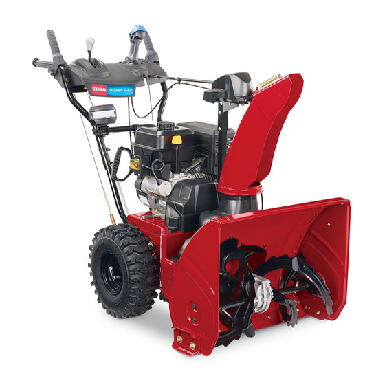
PowerMax Snowthrower
Model No. 38622
Important: Refer to your Operator's Manual for safety,
maintenance, and warranty information.
Setup
1.
Position the upper handle over the lower handle.
Note:
Do not remove
the rubber band until
you have installed the
handle.
Important:
Route the
2 cables attached to the
Quick Stick (A) inside
the upper handle legs.
Do not pinch the cables
or the headlight wire.
2.
Secure the upper handle (fasteners are shown above).
3.
Remove the hairpin
cotter and washer from the
end of the speed control rod
(B) and insert the end into the
lower link arm (C).
4.
Secure the rod end with
the washer and hairpin cotter.
5.
Remove the hairpin cotter and the outer washer from the
trunnion (D) on the upper end of the speed control rod.
Note: Do not remove the wave washer (E) or the flat
washer (F).
6.
Shift the speed
selector lever into
Position R2.
7.
Rotate the lower
link arm up.
m–6971
8.
Lift up the speed control rod and insert the trunnion in the
hole in the speed selector lever (see G above) located under
the control panel.
Note: If the trunnion does not fit into the hole when you lift
up the speed control rod, rotate the trunnion up or down on
the speed control rod until it fits.
E 2005 by The Toro Company
8111 Lyndale Ave., Bloomington, MN 55420, USA
A
m-7698
B
C
m-6899
E
G
D
F
m-6898a
Printed in the USA
All Rights Reserved
9.
Secure the trunnion and upper end of the speed control
rod with the outer washer and a hairpin cotter.
Note: For easier
installation, look down
through the opening in the
speed selector (H).
10. Unwrap the Quick Stick and rotate it so that it is upright
and in the center.
11. Hold the blue cap down and pull the lever fully back.
Note: The discharge chute and deflector should face
forward. If they do not, hold the blue cap down (but do not
move the Quick Stick), and rotate the discharge chute until
they do.
12. Align the flattened end of the long rod (I) with the flattened
end of the short rod (J) that extends from the control panel so
they nest together.
J
13. Insert the long rod
end into the back of the
chute gear cover until it
slides into the gear.
14. Align the holes in the nested ends of the rods and insert 2
bolts through the short rod from the left side (from the
operating position).
15. Insert the cable clip (K)
that supports the deflector
cable (L) on the forward bolt
(M), and secure the bolts with
the locknuts provided.
16. Hold the blue cap down and rotate the Quick Stick in a
circle to ensure that the chute and deflector work smoothly.
17. Insert the wire connector
on the loose end of the wire
straight into the back of the
headlight.
18. Secure a cable tie
around the wire and the
handle about an inch (2.5 cm)
below the U-bolt.
Register your product at www.toro.com
Form No. 3353-603 Rev B
Setup Instructions
H
m-6972
m–6973
I
m-6969
M
L
K
m-7011
Original Instructions (EN)
Advertisement

Related Manuals for Toro PowerMax 38622


Summary of Contents for Toro PowerMax 38622
- Page 1 U-bolt. the speed control rod until it fits. m-7011 E 2005 by The Toro Company Printed in the USA Original Instructions (EN) 8111 Lyndale Ave., Bloomington, MN 55420, USA All Rights Reserved Register your product at www.toro.com...
- Page 2 E 2005 – The Toro Company Imprimé aux États-Unis Traduction de l’original (FR) 8111 Lyndale Ave., Bloomington, MN 55420, États-Unis Tous droits réservés...