Sony DCR-TRV380 Service Manual
Digital video camera recorder
Hide thumbs
Also See for DCR-TRV380:
- Operation manual (156 pages) ,
- Service manual (64 pages) ,
- Operation manual (156 pages)
Table of Contents
Advertisement
Quick Links
DCR-TRV380/TRV480/TRV480E
SERVICE MANUAL
Ver. 1.4 2008.07
Revision History
Revision History
How to use
How to use
Acrobat Reader
Acrobat Reader
Revised-1
Replace the previously issued
SERVICE MANUAL 9-876-781-31
with this manual.
M2000 MECHANISM
Link
Link
SPECIFICATIONS
SPECIFICATIONS
SERVICE NOTE
SERVICE NOTE
DISASSEMBLY
DISASSEMBLY
• For ADJUSTMENTS (SECTION 6), refer to SERVICE MANUAL, ADJ (9-876-781-51).
• For INSTRUCTION MANUAL, refer to SERVICE MANUAL, LEVEL1 (9-876-781-41).
• For MECHANISM ADJUSTMENTS, refer to the "8mm Video MECHANICAL ADJUSTMENT MANUAL
M2000 MECHANISM " (9-929-861-11).
• Reference No. search on printed wiring boards is available.
• Table for differences of function of each model.
• TO TAKE OUT A CASSETTE WHEN NOT EJECT (FORCE EJECT)
• HELP: Sheet attachment positions and procedures of processing the flexible boards/harnesses are shown.
On the VC-345 board
This service manual provides the information that is premised
the circuit board replacement service and not intended repair
inside the VC-345 board.
Therefore, schematic diagrams, printed wiring boards, mounted
parts location and electrical parts list of the VC-345 board are
not shown.
DCR-TRV380/TRV480/TRV480E
9-876-781-32
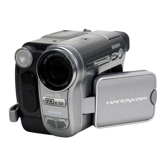
Photo: DCR-TRV480E
BLOCK DIAGRAMS
BLOCK DIAGRAMS
FRAME SCHEMATIC DIAGRAMS
FRAME SCHEMATIC DIAGRAMS
SCHEMATIC DIAGRAMS
SCHEMATIC DIAGRAMS
The following pages are not shown.
Schematic diagrams ..................... Pages 4-9 to 4-44
Printed wiring boards .................... Pages 4-59 to 4-62
Waveforms ..................................... Pages 4-70 to 4-75
Mounted parts location .................. Pages 4-77 and 4-78
Electrical parts list ......................... Pages 5-16 to 5-24
DIGITAL VIDEO CAMERA RECORDER
Sony EMCS Co.
RMT-831
LEVEL
DCR-TRV480
Canadian Model
DCR-TRV480E
North European Model
Australian Model
DCR-TRV380/
TRV480/
TRV480E
PRINTED WIRING BOARDS
PRINTED WIRING BOARDS
REPAIR PARTS LIST
REPAIR PARTS LIST
Published by Kohda TEC
2
US Model
AEP Model
UK Model
E Model
IX
2008G0500-1
© 2008.7
SYS SET
Advertisement
Table of Contents

Related Manuals for Sony DCR-TRV380


Summary of Contents for Sony DCR-TRV380
- Page 1 VC-345 board are Mounted parts location ....Pages 4-77 and 4-78 not shown. Electrical parts list ......Pages 5-16 to 5-24 DIGITAL VIDEO CAMERA RECORDER 2008G0500-1 DCR-TRV380/TRV480/TRV480E © 2008.7 Sony EMCS Co. 9-876-781-32 Published by Kohda TEC SYS SET...
-
Page 2: Repair Parts List
3-078-889-11 SCREW (M1.7) 3-080-204-31 SCREW (1.7X6), TAPPING, P2 3-087-810-11 LID (51), CPC CAUTION : For the part of 8 : RETAINER (51), EVF FLEXIBLE (3-088-616-01), cut WOVEN (T0.25), FABRIC NON DCR-TRV380/TRV480/TRV480E (3-076-631-01) into the desired length and use it. SYS SET... -
Page 3: Front Panel Block
8-719-078-24 DIODE DAC3825 (IR EMITTER) (Note 1) IC751 6-704-975-01 IC RPM7240-V4 (Note 1) 3-088-031-01 CUSHION (51), MICROPHONE J752 1-778-040-11 JACK, SMALL TYPE (A/V OUT) (Note 1) CN751 1-794-276-11 CONNECTOR, SQUARE TYPE 4P (DV) (Note 1) MIC901 1-542-513-11 MICROPHONE DCR-TRV380/TRV480/TRV480E SYS SET... -
Page 4: Lens Block
3-080-204-21 SCREW, TAPPING, P2 1-758-554-11 FILTER BLOCK, OPTICAL IC951 A-7013-401-A CCD BLOCK ASSY (CCD IMAGER) 3-053-973-01 RUBBER (W), SEAL (TRV480E) (Note 1, 2) A-7111-980-A CD-472 BOARD, COMPLETE IC951 A-7016-724-A CCD BLOCK ASSY (CCD IMAGER) (TRV380/TRV480) (Note 1, 2) DCR-TRV380/TRV480/TRV480E SYS SET... -
Page 5: Lcd Block
X-2024-898-1 CABINET (M (970)) ASSY, P 3-088-536-01 CUSHION (61), LCD 3-087-902-01 FRAME (61), PANEL 1-479-063-11 KEY BLOCK, CONTROL (SB-9000) A-1081-090-A PD-205 BOARD, COMPLETE LCD901 8-753-052-10 ACX307AKM-1 3-078-890-21 SCREW, TAPPING 0 ND901 1-518-951-21 TUBE, FLUORESCENT, COLD CATHODE 3-078-889-11 SCREW (M1.7) DCR-TRV380/TRV480/TRV480E SYS SET... -
Page 6: Cabinet R Block
1-962-648-11 HARNESS (PD-124) CAUTION TAPE (CF) 3-087-826-11 COVER (M) (51), HINGE 3-087-825-31 COVER (C) (51), HINGE CAUTION : For the part of 211 : TAPE (CF) (3-090-115-01), cut WOVEN (T0.25), FABRIC NON (3-076-631-01) into DCR-TRV380/TRV480/TRV480E the desired length and use it. SYS SET... -
Page 7: Evf Block
X-3951-166-1 LENS (M) ASSY, VF LCD902 1-805-465-61 INDICATOR MODULE LIQUID CRYSTAL X-2025-533-1 CABINET (LOWER (905)) ASSY, EVF (TRV380/TRV480) 3-080-204-21 SCREW, TAPPING, P2 LCD902 1-805-465-81 INDICATOR MODULE LIQUID CRYSTAL X-2048-474-1 BASE (910) ASSY, SLIDE (TRV480E) 3-080-203-31 SCREW (M2), LOCK ACE, P2 DCR-TRV380/TRV480/TRV480E SYS SET... -
Page 8: Battery Panel Block
Description 3-087-799-01 SHEET METAL (LOWER) (51), STRAP 1-816-271-21 MEMORY STICK CONNECTOR 10P 3-078-889-11 SCREW (M1.7) 1-860-931-11 FP-799 FLEXIBLE BOARD X-2024-900-1 PANEL (970) ASSY, BATTERY 2-583-929-01 SHEET (970), MS SHIELD 3-072-305-11 LID (2500), JACK BT901 1-694-772-11 TERMINAL BOARD, BATTERY DCR-TRV380/TRV480/TRV480E SYS SET... -
Page 9: Md Frame Block
1-860-927-11 FP-796 FLEXIBLE BOARD 2-548-267-41 LABEL (L (95)) (TRV480) A-1093-414-A VC-345 BOARD, COMPLETE (SERVICE) 2-548-267-51 LABEL (L (95)) (TRV480E) (TRV380) 3-080-204-11 SCREW, TAPPING, P2 A-1093-415-A VC-345 BOARD, COMPLETE (SERVICE) 2-583-930-01 SHEET (970), VC SHIELD (TRV480/TRV480E) 1-860-930-11 FP-794 FLEXIBLE BOARD DCR-TRV380/TRV480/TRV480E SYS SET... -
Page 10: Cassette Compartment Assembly, Drum Assembly
X-3951-299-1 SCREW ASSY, DRUM FITTING X-3951-298-1 CASSETTE COMPARTMENT ASSY 3-074-309-01 ROLLER A, LS GUIDE X-3951-302-1 DAMPER ASSY 7-624-101-04 STOP RING 1.2 (E TYPE) X-3951-297-1 GEAR ASSY, R DRIVE M901 A-7048-986-A DRUM (DKH-04B-R) (SERVICE) 3-065-840-01 CUT (0.98X3X0.13), LUMILER (W) DCR-TRV380/TRV480/TRV480E 5-10 SYS SET... -
Page 11: Ls Chassis Block Assembly
8-729-907-25 PHOTO TRANSISTOR PT4850F (TAPE END) 3-071-650-01 SCREW (M1.7) (S) S001 1-692-614-11 SWITCH, PUSH (3 KEY) (REC PROOF) 3-065-832-01 PLATE, LS CAM 3-065-828-01 ARM, S RATCHET S002 1-572-688-11 SWITCH, PUSH LEVER (1 KEY) (C. C. LOCK) 3-065-829-01 PLATE, S RATCHET (RE) DCR-TRV380/TRV480/TRV480E 5-11 SYS SET... -
Page 12: Mechanical Chassis Block Assembly
1-677-049-11 FP-228 FLEXIBLE BOARD (DEW SENSOR) 3-065-882-01 ARM, EJECT 1-680-434-11 FP-299 FLEXIBLE BOARD M902 8-835-701-01 MOTOR, DC SCE13A/C-NP (CAPSTAN) 3-065-877-01 PLATE (T), GUIDE LOCK M903 A-7096-420-A MOTOR ASSY, LD (LOADING) X-3951-301-1 PLATE ASSY, PINCH PRESSURE S901 1-786-096-11 SWITCH, ROTARY (MODE SWITCH) DCR-TRV380/TRV480/TRV480E 5-12 SYS SET... - Page 13 3-065-901-01 ROLLER, LS ARM 3-065-915-01 GEAR (1), CAM 3-065-916-01 GEAR (2), CAM 3-065-878-01 PLATE (S), GUIDE LOCK 3-065-919-01 ARM, T1 LIMITTER 3-065-932-01 PAN (2 MAIN M1.4X1.6), CAMERA X-3951-308-1 ARM ASSY, GL A-7096-413-A GEAR (S) ASSY, GUIDE X-3951-300-2 CHASSIS ASSY, MECHANICAL DCR-TRV380/TRV480/TRV480E 5-13 SYS SET...
- Page 14 0 or dotted line with marque 0 sont critiques pour la mark 0 are critical for safety. sécurité. Replace only with part num- Ne les remplacer que par une pièce ber specified. portant le numéro spécifié. DCR-TRV380/TRV480/TRV480E 5-25E SYS SET...