Table of Contents
Advertisement
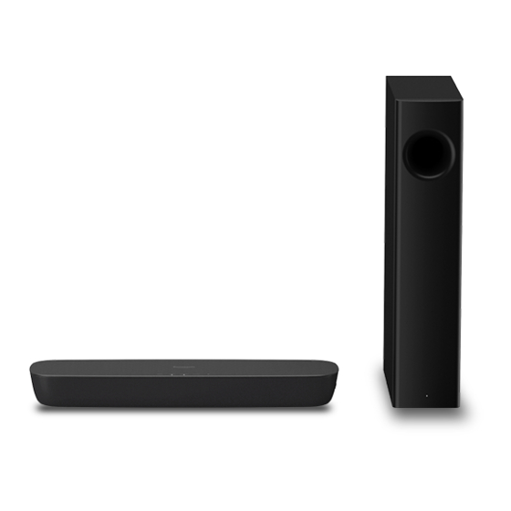
Home Theater Audio System
This illustration shows SC-HTB250.
EG
GN
15 Jan 2018
This service information is designed for experienced repair technicians only and is not designed for use by the general
public. It does not contain warnings or cautions to advise non-technical individuals of potential dangers in attempting
to service a product. Products powered by electricity should be serviced or repaired only by experienced professional
technicians. Any attempt to service or repair the product or products dealt with in this service information by anyone else
could result in serious injury or death.
Operating Instructions
Model No.
SB-HWA250
SU-HTB250
SC-HTB258
SC-HTB250
SC-HTB208
SC-HTB200
Home Theater Audio System
Model No.
Remote
Control
Colour:(K)...........Black Type
TQBJ2086
WARNING
© Panasonic Corporation 2018
Unauthorized copying and distribution is a violation of law.
ORDER NO.PSG1804014CE
SC-HTB250GA
SC-HTB250GJ
SU-HTB250GA
SU-HTB250GJ
SB-HWA250GA
SB-HWA250GJ
Advertisement
Table of Contents

Related Manuals for Panasonic SC-HTB250GA


Summary of Contents for Panasonic SC-HTB250GA
- Page 1 Any attempt to service or repair the product or products dealt with in this service information by anyone else could result in serious injury or death. © Panasonic Corporation 2018 Unauthorized copying and distribution is a violation of law.
-
Page 2: Table Of Contents
TABLE OF CONTENTS PAGE 1 Safety Precautions ----------------------------------------------- 3 1.1. General Guidelines ----------------------------------------- 3 1.2. Leakage Current Cold Check ----------------------------- 3 1.3. Leakage Current Hot Check ------------------------------- 3 1.4. Protection Circuitry------------------------------------------- 3 2 Warning -------------------------------------------------------------- 4 2.1. Prevention of Electrostatic Discharge (ESD) to Electrostatically Sensitive (ES) Devices ------------ 4 2.2. -
Page 3: Safety Precautions
1 Safety Precautions 1.1. General Guidelines 1. IMPORTANT SAFETY NOTICE There are special components used in this equipment which are important for safety. These parts are marked by the Schematic Diagrams, Circuit Board Layout, Exploded Views and Replacement Parts List. It is essential that these critical parts should be replaced with manufacturer’s specified parts to prevent X-RADIATION, shock, fire, or other hazards. -
Page 4: Warning
2 Warning 2.1. Prevention of Electrostatic Discharge (ESD) to Electrostatically Sensitive (ES) Devices Some semiconductor (solid state) devices can be damaged easily by static electricity. Such components commonly are called Electrostatically Sensitive (ES) Devices. Examples of typical ES devices are IC(integrated circuits)and some field-effect transistors and semiconductor “chip”... -
Page 5: Service Caution Based On Legal Restrictions
2.2. Service Caution Based on Legal Restrictions 2.2.1 General Description About Lead Free Solder (PbF) The lead free solder has been used in the mounting process of all electrical components on the printed circuit boards used for thisequipment in considering the globally environmental conservation. The normal solder is the alloy of tin (Sn) and lead (Pb). -
Page 6: Service Navigation
3 Service Navigation 3.1. Service Information This service manual contains technical information, which allow service personnels to understand and service this model. Please place orders with the numbers in the parts list and not the numbers in the exploded views. If the circuit is changed or modified, the information will be followed by supplement to be filed with original service manual. - Page 7 ① Download the software (binary file) from website below to USB Audio customer support website (※ Use the USB 2.0 memory and copy files to the root folder ) Software download http://av.jpn.support.panasonic.com/support/global/cs/audio/ xxx.bin ② In HDMI (ARC) mode, insert the USB Device into the USB port Copy to USB memory...
-
Page 8: Specifications
4 Specifications AMPLIFIER SECTION WIRELESS SECTION Wireless module RMS output power: Dolby Digital Mode Frequency Range 2404 MHz to 2476 MHz Front ch No. of channels 40 W per channel (6 Ω),1 kHz,10%, THD Subwoofer ch RF output power 40 W per channel (4 Ω),100 Hz,10%, THD 7 dBm (max.) Total RMS Dolby Digital mode power GENERAL... -
Page 9: Location Of Controls And Components
5 Location of Controls and Components Overview of controls Main unit Active subwoofer HDMI (ARC) OPTICAL... - Page 10 Preparing the remote control Remote control Before using for the first time SOUND SUBWOOFER INPUT PAIRING MUTE Replacing the battery ALBUM HDMI (ARC) OPTICAL...
-
Page 11: Service Mode
controller from the flash memory to USB device for service personnel confirmation use. Steps Service Mode 1. Turn on the unit. This unit has service mode function that can resave the operation record of unit keys or the remote controller from the flash 2. - Page 12 How to read the Operation Record • Last 200 times operations are recorded.(May more or less due to different status. This chapter describes the case based on the 200 times.) • The last 200 times operations are recorded following left to right, top to down order started from the third number at the up left corner.
-
Page 13: Troubleshooting Guide
7 Troubleshooting Guide Main Unit (SU-HTB250) 7.1.1 No power No power Check the Main C133~C165 Check the Main U16 Check the Main C117~U16 Press the Power No power LED not light up. power output at 24V Pin 5 for 5.2V Pin 8 for 3.3V button on the unit to [Refer to check point ①]... - Page 14 Go to Change “No Sound (Bluetooth®)” LED PCB 7.1.4. No Key Function No Key Function Check the Main 3.3V at Pin 2/3/4/5/6 3.3 V at Pin 2/3/4/5/6 Press remote control Connect the AC C117~U16 Pin 8 of Main CP4 of Key CN4 Change “Power”...
- Page 15 Connect correctly or 7.1.7. No Sound change the cable 7.1.7.1. No Sound (Bluetooth®) No Sound (Bluetooth®) No HDMI ARC If the pairing failure, Go to “Bluetooth® Pairing failure” Press the Power Connect Playback Change button to turn on Press the Power select “HDMI(ARC)”...
- Page 16 7.1.8. Check Points MAIN P.C.B. 5.2V C117 3.3V (C117~U16 Pin8) Pin 8 of Main CP2 Pin 2/3/4/5/6 of Main CP4...
- Page 17 KEY P.C.B. Pin 2/3/4/5/6 of Key CN4 IR P.C.B. Pin 8 of IR CN2...
-
Page 18: Active Subwoofer (Sb-Hwa250)
No power No power Active Subwoofer (SB-HWA250) 7.2.1 No power Check the cable is Check the Main L4 5.2V Check the Main Q1 Connect the AC connected correctly at “5.2V” power output at 24V Check the cable is LED not light up Check the Main L4 5.2V Check the Main Q1 (Main J5 to Wireless J2) -
Page 19: Wiring Connection And Voltage Data
8 Wiring Connection and Voltage Data Main Unit (SU-HTB250) MAIN P.C.B. U16 LDO U17 LDO U14 DC-DC WIRELESS TX TD7286 AME8816 AZ1117D M8307 MODULE P.C.B. U18 LDO U15 DC-DC TD7286 APL5320 U8 FET TAS5731M NCE40P13S KEY P.C.B. IR P.C.B. DC OUT POWER P.C.B. - Page 20 VOLTAGE DATA (measurement status:Power On and No external signal input ) PIN NO. VALUE PIN NO. VALUE 5.2V CN207 5.2V PIN NO. VALUE XP114 5.2V PIN NO. VALUE 3.3V 3.3V 3.3V 1.68V 1.66V PIN NO. VALUE 1.68V 3.3V 3.3V 3.3V 3.3V 3.3V 3.3V...
-
Page 21: Active Subwoofer (Sb-Hwa250)
Active Subwoofer (SB-HWA250) POWER P.C.B. AC IN CON1 DC OUT KEY P.C.B. DC-DC TD1465A LN1134A TAS5731M WIRELESS MODULE SUB IN P.C.B. LED P.C.B. MAIN P.C.B. - Page 22 VOLTAGE DATA (measurement status:Power On and No external signal input ) PIN NO. VALUE PIN NO. VALUE PIN NO. VALUE 2.67V CN207 PIN NO. VALUE 5.2V 5.2V 3.3V 3.24V 3.3V 5.2V 3.3V 3.3V 3.3V 1.68V 1.66V 3.3V 1.68V 3.3V PIN NO. VALUE 3.2V XP114...
-
Page 23: Disassembly And Assembly Instructions
9 Disassembly and Assembly Instructions 9.1. Disassembly Flow Chart The following chart is the procedure of disassembling the casing and inside parts for internal inspection when carrying out the servicing. To assemble the unit, reverse the steps shown in the chart below. 9.1.1 Main Unit (SU-HTB250) 1.Top Cabinet Unit... -
Page 24: Positions
9.2. P.C.B. Positions 9.2.1 Main Unit (SU-HTB250) Main P.C.B. Power P.C.B. Wireless TX Module P.C.B. Speaker 2 LED P.C.B. IR P.C.B. Speaker 1 Key P.C.B. 9.2.2 Active Subwoofer (SB-HWA250) Wireless RX Module P.C.B. I/D Set P.C.B. Main P.C.B. Woofer Speaker Power P.C.B. -
Page 25: Disassembly Procedure Of Main Unit (Su-Htb250)
9.3. Disassembly Procedure of Main Unit (SU-HTB250) 9.3.1. Top Cabinet Unit 1. Remove 10 Black Screws (A) on the bottom cabinet. Black Screw (A) Black Screw (A) 2. Upset main unit and lift up the Top Cabinet Unit. 3. Disconnect connector (A) and remove the Top Cabinet Unit. Top Cabinet Unit Connector (A) - Page 26 9.3.2. Main P.C.B. 1. Remove 5 Black Screws (C). 2. Disconnect connector (A)-(E) and FFC cable. 3. Remove the Main P.C.B.. Connector(E) Connector(A) Connector(C) Black Screw (C) Main P.C.B. Black Screw (C) FFC cable Connector(D) Black Screw (C) Black Screw (C) Connector(B) 9.3.3.
- Page 27 9.3.4. Power P.C.B. 1. Remove 4 Black Screws (C). 2. Disconnect connector (A),(B). 3. Remove the Power P.C.B.. Black Screw (C) Connector (B) Power P.C.B Connector (A) 9.3.5. Key P.C.B. 1. Remove 3 Black Screws (C). 2. Lift up the the Key P.C.B. & Key Button straightly. 3.
- Page 28 9.3.6. AC Inlet Unit 1. Remove 2 Black Screws (D). 2. Disconnect connector (A). 3. Remove the AC Inlet Unit. Connector(A) AC Inlet Unit Black Screw (D) 9.3.7. Speaker Net Frame Unit 1. Remove 4 Black Screws (C). 2. Remove the Speaker Net Frame Unit. Speaker Net Frame Unit Black Screw (C) Black Screw (C)
- Page 29 9.3.9. Speaker 1. Disconnect 2 Speaker Cable Terminals. 2. Remove 4 Black Screws (C). 3. Remove Speaker 1. 4. Remove Speaker 2 in the same way. Speaker 2 Speaker 1 Speaker Cable Terminal(+) Speaker Cable Terminal(-) Black Screw (C) 9.3.10. LED P.C.B.
-
Page 30: Disassembly Procedure Of Of Active Subwoofer (Sb-Hwa250)
9.4. Disassembly Procedure of Active Subwoofer (SB-HWA250) 9.4.1. Back Panel Unit (AC Cord) 9.4.2. I/D Set P.C.B. 1. Remove 6 Black Screws (A). 1. Remove 2 Black Screws (B). 2. Remove the I/D Set P.C.B.. I/D Set P.C.B. Black Screw (B) Black Screw (A) 9.4.3. - Page 31 9.4.5. Wireless RX Module P.C.B. 2. Remove 4 Black Screws (C). 1. Disconnect FFC cable. 2. Pull out the Sponge by thin brade driver in the direction of 3. Slightly lift up Woofer Speaker in the direction of arrow. 4.Disconnect speaker wire. arrow (1).
-
Page 32: Exploded View And Replacement Parts List
10 Exploded View and Replacement Parts List 10.1. Casing Parts & Mechanism Section (SU-HTB250) 18-1 18-1 18-1 18-1... -
Page 33: Casing Parts & Mechanism Section (Sb-Hwa250)
10.2. Casing Parts & Mechanism Section (SB-HWA250) -
Page 34: Packing & Accessories Section
10.3. Packing & Accessories Section (SC-HTB250) SB-HWA250 SU-HTB250... -
Page 35: Replacement Parts List
10.4. Replacement Parts List Notes: *Important safety notice: Components identified by mark have special characteristics important for safety. When replacing any components, be sure to use only manufacture’s specified parts shown in the parts list. *All Parts are supplied by PHK. 10.4.1. - Page 36 10.4.3. Packaging & Accessories (SC-HTB250) Ref. Safety Part No. Part Name & Description Remarks A1 TMKK727 RUBBER LEG OPERATING A2 TQBJ2089 INSTRUCTIONS A3 TSXA168 AC CORD 1 250GA A3 TSXA175 AC CORD 1 250GJ A4 RSQ0159 OPTICAL CABLE A5 N2QAYC000125 REMOTE CONTROLLER P1 TPDA33481 POLYFOAM (T) P2 TPEH938...