
Related Manuals for Bosch UML-151


Summary of Contents for Bosch UML-151
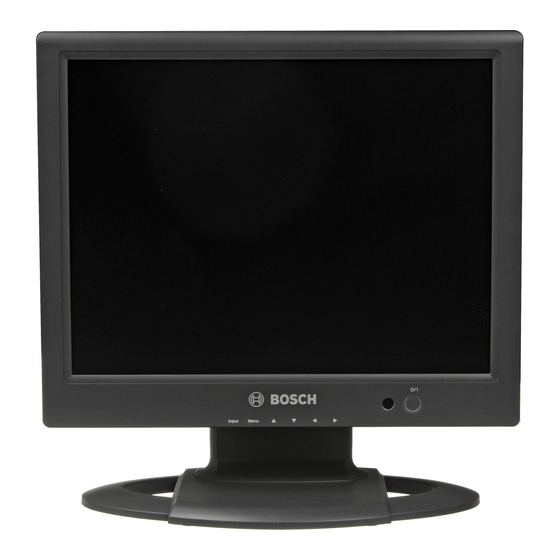
- Page 1 General Purpose LCD Monitors UML-151-90 | UML-171-90 | UML-191-90 User’s Manual...
-
Page 3: Table Of Contents
Navigating the Monitor Navigating the Front Panel Navigating the Monitor On-screen Display (OSD) On-screen Display Menus Custom Menu Picture / Sound Menu Setup Menu Bosch Security Systems, Inc. User’s Manual Table of Contents | en F.01U.127.338 | 2.0 | 2009.05... - Page 4 | Table of Contents Power Management Power Consumption LED Indicator Trouble Shooting Guide Maintenance Technical Specifications F.01U.127.338 | 2.0 | 2009.05 User’s Manual General Purpose LCD Monitors Bosch Security Systems, Inc.
-
Page 5: Safety
ON/OFF switch is in the ON position. The power cord is the main power disconnect device for switching off the voltage for all units. Bosch Security Systems, Inc. User’s Manual Safety | en... - Page 6 17. Attachments, changes or modifications - Only use attachments/accessories specified by the manufacturer. Any change or modification of the equipment, not expressly approved by Bosch, could void the warranty or, in the case of an authorization agreement, authority to operate the equipment.
-
Page 7: Safety Precautions
-10 °C (14 °F) to 50 °C (122 °F). Camera signal - Protect the cable with a primary protector if the camera signal is beyond 140 feet, in accordance with NEC800 (CEC Section 60). Bosch Security Systems, Inc. User’s Manual Safety | en... - Page 8 Please dispose of these units at an environmentally compatible recycling facility, per European Directive 2002/96/EC. Environmental statement - Bosch has a strong commitment towards the environment. This unit has been designed to respect the environment as much as possible.
- Page 9 Because the ISDN circuits are treated like telephone-network voltage, avoid connecting the SELV circuit to the Telephone Network Voltage (TNV) circuits. Video loss - Video loss is inherent to digital video recording; therefore, Bosch Security Systems cannot be held liable for any damage that results from missing video information. To minimize the risk of lost digital information, Bosch Security Systems recommends multiple, redundant recording systems, and a procedure to back up all analog and digital information.
- Page 10 UL MAKES NO REPRESENTATIONS, WARRANTIES, OR CERTIFICATIONS WHATSOEVER REGARDING THE PERFORMANCE OR RELIABILITY OF ANY SECURITY OR SIGNALING- RELATED FUNCTIONS OF THIS PRODUCT. F.01U.127.338 | 2.0 | 2009.05 User’s Manual General Purpose LCD Monitors Bosch Security Systems, Inc.
- Page 11 General Purpose LCD Monitors Copyright This user guide is the intellectual property of Bosch Security Systems, Inc. and is protected by copyright. All rights reserved. Trademarks All hardware and software product names used in this document are likely to be registered trademarks and must be treated accordingly.
-
Page 12: Customer Support And Service
| Safety Customer Support and Service If this unit needs service, contact the nearest Bosch Security Systems Service Center for authorization to return and shipping instructions. Service Centers Telephone: 800-366-2283 or 585-340-4162 Fax: 800-366-1329 Email: cctv.repair@us.bosch.com Customer Service Telephone: 888-289-0096 Fax: 585-223-9180 Email: security.sales@us.bosch.com... -
Page 13: Unpacking
Verify that all the parts listed in the Parts List below are included. If any items are missing, notify your Bosch Security Systems Sales or Customer Service Representative. The original packing carton is the safest container in which to transport the unit and must be used if returning the unit for service. -
Page 14: Exploded View
Indicator Standby (blinking red) Unsupported Mode (green) Power Off (red) User’s Manual General Purpose LCD Monitors Scrolls up in the OSD. Scrolls down in the OSD. Scrolls left in the OSD. Scrolls right in the OSD. Bosch Security Systems, Inc. - Page 15 General Purpose LCD Monitors Figure 3.2 Bottom Panel Reference # 9, 10 Bosch Security Systems, Inc. Connector Description DC 12 V IN UML-151-50: 3.3 A UML-171-50: 4.1 A UML-191-90: 4.1 A VGA IN PC Signal Input VIDEO 1 (AV1) IN...
-
Page 16: Remote Control
| Remote Control Remote Control This section details the functions and the usage of the Bosch remote control. Button Function POWER Turns the power ON and OFF. SOURCE Selects the PC or Video source. APC (Auto Selects the Picture mode. Continuously press this button Picture Control) to change the selection. -
Page 17: Description
General Purpose LCD Monitors Description The Bosch General Purpose Family of LCD monitors display PAL or NTSC standard color pictures in CCTV systems. Two (2) looping Composite Video BNC connector inputs and one (1) looping Y/C (S-Video) input using a 4-pin mini-DIN are included with each model. In addition, each works with a VGA signal. -
Page 18: Mounting The Monitor
6.2.1 Desktop Installation The Bosch General Purpose monitors are delivered with a 3-pole US-style power cord and a 3- pole Euro-style power cord. Use the US-style power cord where 120 VAC, 60 Hz power is available; use the Euro-style power cord where 230 VAC, 50 Hz power is available. The monitor automatically adjusts to either power input voltage. -
Page 19: Connecting The Composite Video Signal To The Monitor
Mount the unit to the mounting device (not provided) using the four (4) mounting holes on the rear panel. The square mounting hole patterns are standard on 100 mm (3.9 in.) centers. Four (4) M4 x 10 mm screws are required and are provided with the Bosch mounting kit. -
Page 20: Connecting The Y/C (S-Video) Signal To The Monitor
Figure 6.5 Single Monitor Configuration Reference # F.01U.127.338 | 2.0 | 2009.05 Input Y-signal IN or OUT C-signal IN or OUT Description Video Camera VIDEO 1 (AV1) IN VIDEO 1 (AV1) OUT User’s Manual General Purpose LCD Monitors Bosch Security Systems, Inc. -
Page 21: Navigating The Monitor
Navigating the Monitor Navigating the Front Panel Use the front panel to make any necessary OSD adjustments to the UML-151-90, UML-171-90, or the UML-191-90. See the figure below for an explanation of the front panel. Figure 7.1 Front Panel Buttons Reference # Button Bosch Security Systems, Inc. -
Page 22: Navigating The Monitor On-Screen Display (Osd)
| Navigating the Monitor Navigating the Monitor On-screen Display (OSD) The UML-151-90, UML-171-90, and the UML-191-90 have two (2) modes: Video and VGA. The LCD is programmed through the on-screen display (OSD) menus and submenus where an operator can select operating parameters. To access the OSD menus, press the Menu button. -
Page 23: On-Screen Display Menus
Table 7.1 Custom Menu (Video Mode) Custom :Move Table 7.2 Custom Menu (PC Mode) Bosch Security Systems, Inc. Function Adjusts the Brightness, Contrast, Color, Tint, and the Sharpness level for video performance of the OSD. (The menu options differ between the Video and PC modes.) -
Page 24: Picture / Sound Menu
Adjusts the sharpness level for video performance (range 0-100). Picture Mode Custom Color Tone Normal Mute Volume Size 3D Comb :Input :Menu Picture Mode Custom Color Tone Normal Mute Volume Size :Input :Menu User’s Manual General Purpose LCD Monitors Bosch Security Systems, Inc. -
Page 25: Setup Menu
Setup submenu. Setup :Move Table 7.5 Setup Menu Bosch Security Systems, Inc. Definition Selects the automatic picture control mode. Choices are: Custom: User selected values of the Custom menu are applied. Dynamic: Automatically adjusts the Brightness, Contrast, and Sharpness, maximizing the video quality in the picture. -
Page 26: Power Management
Off: displays a black backgound when video loss is detected. Enables or disables the Key Lock function. 25 W 40 W 45 W < 5.0 W < 5.0 W < 5.0 W User’s Manual General Purpose LCD Monitors Bosch Security Systems, Inc. -
Page 27: Trouble Shooting Guide
PC mode Incorrect colors The error message “Unsupport Mode” is displayed Bosch Security Systems, Inc. Solution – Check that the power cord of the monitor is securely connected into the wall outlet or grounded extension cable or strip. -
Page 28: Maintenance
Ethyl alcohol – Ethyl acid – Toluene – Methyl chloride – Ammonia Use of these materials may permanently damage the polarizer due to a chemical reaction. F.01U.127.338 | 2.0 | 2009.05 User’s Manual General Purpose LCD Monitors Bosch Security Systems, Inc. -
Page 29: Technical Specifications
Composite Video (CVBS) 1.0 Vp-p (0.5–1.5 Vp-p), automatic switching from 75 W unbalanced termination to Hi-Z with passive loop-through operation Y/C (S-video) 0.7 Vp-p (Y-signal), 0.3 Vp-p (C-signal), 75 W termination Bosch Security Systems, Inc. Technical Specifications | en UML-171-90 120/230 VAC, 50/60 Hz... - Page 30 60/75 Hz Input: 100–240 VAC, 50/60 Hz Input: 100–240 VAC, 50/60 Hz Output: 12 VDC, 4.1 A Output: 12 VDC, 4.1 A User’s Manual General Purpose LCD Monitors 60/72/75 Hz 60/72/75 Hz 60/70/75 Hz 60/75 Hz Bosch Security Systems, Inc.
- Page 31 Maximum 90%, non-condensing Parts Included One (1) Bosch General Purpose Color LCD Flat Panel Monitor One (1) VGA to VGA cable Two (2), 3-wire power cords with a grounded plug: one (1) with a European/Continental plug type and one (1) with a U.S.
- Page 32 | Technical Specifications General Purpose LCD Monitors F.01U.127.338 | 2.0 | 2009.05 User’s Manual Bosch Security Systems, Inc.
- Page 34 Telephone +1 888-289-0096 +1 585-223-9180 Email: security.sales@us.bosch.com www.boschsecurity.us © Bosch Security Systems, 2009; F.01U.127.338 | 2.0 | 2009.05; Data subject to change without notice. Europe, Middle East, Africa: Bosch Security Systems B.V. P.O. Box 80002 5600 JB Eindhoven, The Netherlands...