Motorola CM Series Service, Maintainability
Commercial series
Hide thumbs
Also See for CM Series:
- Service information (90 pages) ,
- Service information (26 pages) ,
- Basic service manual (74 pages)
Table of Contents
Advertisement
Quick Links
Advertisement
Table of Contents

Related Manuals for Motorola CM Series


Summary of Contents for Motorola CM Series
- Page 1 Commercial Series CM Radios Service Maintainability Issue: October 2004...
- Page 2 Accordingly, any copyrighted Motorola computer programs contained in the Motorola products described in this manual may not be copied or reproduced in any manner without the express written permission of Motorola. Furthermore, the purchase of Motorola...
- Page 3 Your Motorola 2-way radio has an RF exposure product label. Do not remove this RF exposure label from the device. Also, your Motorola user manual, or separate safety booklet, includes information and operating instructions required to control your RF exposure and to satisfy compliance requirements.
- Page 4 90 cm (3 Ft) If you are not sure of the rated power of your radio, contact your Motorola representative or dealer and supply the radio model number found on the radio model label. If you cannot determine the rated...
- Page 5 RF Safety Standards. Approved Accessories This radio has been tested and meets the RF Safety Standards when used with the Motorola acces- ● sories supplied or designated for this product. Use of other accessories may result in non-compli- ance with RF Safety Standards.
- Page 6 Electromagnetic Interference/Compatibility Note: Nearly every electronic device is susceptible to electromagnetic interference (EMI) if inadequately shielded, designed or otherwise configured for electromagnetic compatibility. It may be necessary to conduct compatibility testing to determine if any electronic equipment used in or around vehicles or near fixed site antenna is sensitive to external RF energy or if any procedures need to be followed to eliminate or mitigate the potential for interaction between the radio transmitter and the equipment or device.
- Page 7 OPERATIONAL WARNINGS Vehicles with an air bag WARNING: Do not mount or place a mobile radio in the area over an air bag or in the air bag deployment area. Air bags inflate with great force. If a radio is placed in the air bag deployment area and the air bag inflates, the radio may be propelled with great force and cause serious injury to occupants of the vehicle.
- Page 8 viii...
-
Page 9: Table Of Contents
Table of Contents Chapter 1 INTRODUCTION 1.0 Scope of Manual ....................1-1 2.0 Warranty and Service Support................1-1 2.1 Warranty Period and Return Instructions ............1-1 2.2 After Warranty Period ..................1-1 2.3 European Radio Support Centre (ERSC)............1-2 2.4 Parts Identification and Ordering ..............1-2 2.5 EMEA Test Equipment Support..............1-2 2.6 Technical Support...................1-3 2.7 Related Documents ..................1-3... -
Page 11: Chapter 1 Introduction
In instances where the product is covered under a "return for replacement" or "return for repair" warranty, a check of the product should be performed prior to shipping the unit back to Motorola. This is to ensure that the product has been correctly programmed or has not been subjected to damage outside the terms of the warranty. -
Page 12: European Radio Support Centre (Ersc)
Aftermarket and Accessory Division (AAD). If no part number is assigned, the part is not normally available from Motorola. If the part number is appended with an asterisk, the part is serviceable by Motorola Depot only. If a parts list is not included, this generally means that no user-serviceable parts are available for that kit or assembly. -
Page 13: Technical Support
Warranty and Service Support Technical Support Motorola Product Services is available to assist the dealer/distributors in resolving any malfunctions which may be encountered. UK/Ireland - Richard Russell Telephone: +44 (0) 1256 488 082 Fax: +44 01256 488 080 Email: BRR001@email.mot.com... -
Page 14: Radio Model Information
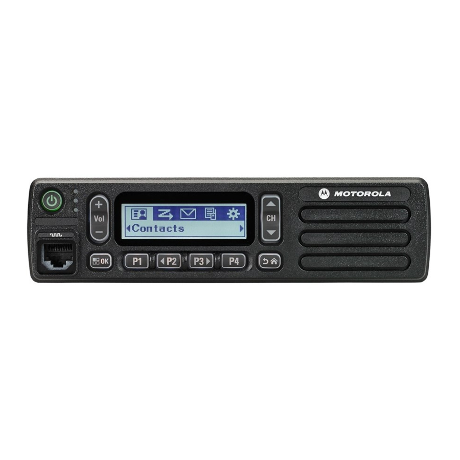
INTRODUCTION Radio Model Information The model number and serial number are located on a label attached to the back of your radio. You can determine the RF output power, frequency band, protocols, and physical packages. The example below shows one mobile radio model number and its specific characteristics. Table 1-1 Radio Model Number (Example: MDM50FNC9AN2_N) Type of Model... -
Page 15: Chapter 2 Maintenance
Chapter 2 MAINTENANCE Introduction This chapter of the manual describes: ■ preventive maintenance ■ safe handling of CMOS devices ■ repair procedures and techniques Preventive Maintenance The radios do not require a scheduled preventive maintenance program; however, periodic visual inspection and cleaning is recommended. Inspection Check that the external surfaces of the radio are clean, and that all external controls and switches are functional. -
Page 16: Safe Handling Of Cmos And Ldmos
When damaged parts are replaced, identical parts should be used. If the identical replacement component is not locally available, check the parts list for the proper Motorola part number and order the component from the nearest Motorola Communications parts center listed in the “Piece Parts”... - Page 17 General Repair Procedures and Techniques Chip Components Use either the RLN4062 Hot-Air Repair Station or the Motorola 0180381B45 Repair Station for chip component replacement. When using the 0180381B45 Repair Station, select the TJ-65 mini- thermojet hand piece. On either unit, adjust the temperature control to 370 °C (700 °F), and adjust the airflow to a minimum setting.
- Page 18 MAINTENANCE Shields Removing and replacing shields will be done with the R1070 station with the temperature control set to approximately 215°C (415°F) [230°C (445°F) maximum]. ■ To remove the shield: Place the circuit board in the R1070 circuit board holder. Select the proper heat focus head and attach it to the heater chimney.
-
Page 19: Notes For All Schematics And Circuit Boards
1. Unless otherwise stated, resistances are in Ohms (k = 1000), and capacitances are in picofarads (pF) or microfarads (µF). 2. DC voltages are measured from point indicated to chassis ground using a Motorola DC multimeter or equivalent. Transmitter measurements should be made with a 1.2 µH choke in series with the voltage probe to prevent circuit loading. - Page 20 MAINTENANCE MIC_PTT_CH Microphone PTT Input MOD_IN Modulation Signal from ASFIC MOD_OUT Modulation Signal to the Synthesizer ONOFF_SENSE On off sense switch OPT_DATA_R_OPRD DATA/Ready Request from Option Board OPT_EN_OPBD Option Board Chip Select PA_BIAS PA Control bias voltage PA_CURRENT Not used POST_LIMITER_TX Flat TX Input from Option Board AUDIO_RETURN_OPT_BRD...
- Page 21 Notes For All Schematics and Circuit Boards VS AUDIO_SEL Switch signal to Enable option board audio output signal VS GAIN_SEL Voice Storage Gain Select line VS_MIC Voice Storage Audio Signal to microphone path VS_INT Voice Storage Interrupt line VS_RAC Voice storage Row Address Clock Signal VSTBY 3.3 V supply for µP when the radio is switched off...
- Page 22 MAINTENANCE...
-
Page 23: Chapter 3 Service Aids
Table 3.1 lists the service aids recommended for working on the radio. While all of these items are available from Motorola, most are standard workshop equipment items, and any equivalent item capable of the same performance may be substituted for the item listed. - Page 24 SERVICE AIDS Table 3-1 Service Aids Motorola Part Description Application 3080369B72 Computer Interface Cable Connects the RIB to the Computer (9-pin) (Use for IBM PC AT - other IBM models use the B71 cable above). 6686119B01 Removal Tool Assists in the removal of radio control head.
-
Page 25: Test Equipment
Test Equipment Test Equipment Table 3-2 lists test equipment required to service the radio and other two-way radios. Table 3-2 Recommended Test Equipment Motorola Part Description Characteristics Application R2600_NT Comms System This monitor will Frequency/deviation meter Analyzer (non MPT) substitute for items with... - Page 26 SERVICE AIDS...