Advertisement
Quick Links
Advertisement

Related Manuals for Samsung DVM Chiller


Summary of Contents for Samsung DVM Chiller
- Page 1 Rev 2.0...
- Page 2 This presentation is provided as a guide to help HVAC field technicians understand the proper procedures for installing Samsung DVM Chiller systems. This training module is not intended to replace Samsung service manuals, technical data books, installation/operation manuals or other factory documents.
- Page 3 Training Topics ▪ Chiller Introduction ▪ Chiller System Components ▪ Chiller Basic Installation ▪ Basic System Commissioning ▪ SNET Pro 2 ▪ Addendum Always refer to the DVM Chiller and Module Controller IOM’s when installing any DVM Chiller system NOTE:...
- Page 4 Chiller Introduction...
- Page 5 DVM Chiller Introduction DVM Pro Design Software ▪ Every DVM Chiller project must be designed through DVM Pro ▪ Insures all system components are compatible ▪ Insures correct layout of all system components ▪ Insures that system will perform as designed...
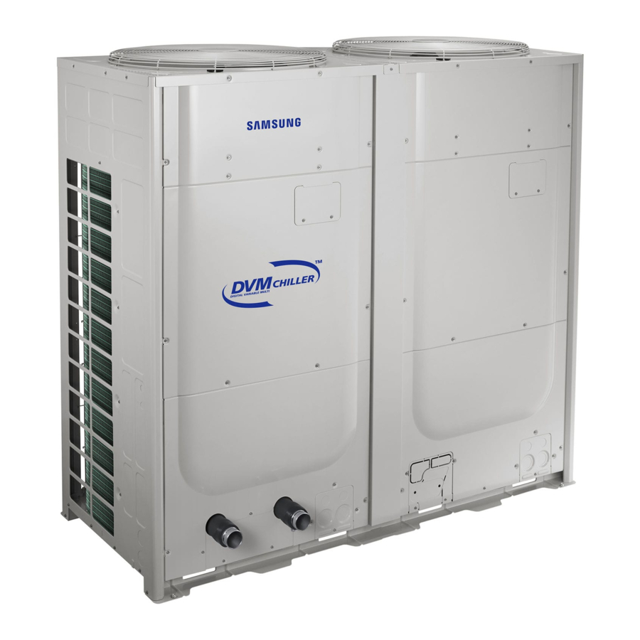
- Page 6 DVM Chiller Introduction DVM Chiller Overview The DVM Chiller is an air to water heat pump ▪ Chill water temperature range: 41°F to 77°F ▪ Chill water temp down to 14°F with antifreeze ▪ Hot water temperature range: 77°F to 131°F ▪...
- Page 7 Selectable snow accumulation removal setting ▪ Sound rating 60dB (A) ▪ Maximum operating water pressure: 145 psi ▪ Compatible with Samsung centralized controls ▪ Touch Controller, DMS 2.5, BACnet & LonWorks Gateways Dedicated module remote controller – MCM-A00N (required) ▪...
- Page 8 DVM Chiller Introduction DVM Chiller Operation Patterns – System Design Chiller system hierarchy overview ▪ Unit – One DVM Chiller unit (10 or 15 ton) ▪ Module – 1 to 8 units connected together (required configuration) 1 Unit module 2 Unit module...
- Page 9 DVM Chiller Introduction DVM Chiller Operation Patterns – System Design Chiller system hierarchy overview ▪ Group – Consists of 2 to 8 modules with a maximum of 16 chiller units per group Example: One group with up to 16 units can be controlled by a single Module Controller...
- Page 10 DVM Chiller Introduction DVM Chiller Operation Control Patterns Selectable chiller group operation control patterns Standard Control – Applications with high cooling/heating load factors ▪ All modules in the group start simultaneously ▪ Individual unit capacity control is based on the water outlet temperature sensor of each unit ▪...
- Page 11 DVM Chiller Introduction DVM Chiller Operation Control Patterns Selectable chiller group operation control patterns Rotation Control – Applications with lower loads at system startup and with small load fluctuations ▪ Chiller’s water outlet temperature is controlled based on the average temperature of all units in the module ▪...
- Page 12 DVM Chiller Introduction DVM Chiller Operation Control Patterns Selectable chiller group operation control patterns ▪ Efficiency Control – Applications where the controlled area has a low load ▪ System capacity control uses an average leaving water temperature of all operating units in a module ▪...
- Page 13 DVM Chiller Introduction DVM Chiller Operation Control Patterns Water Law Control – Applications where efficiency is increased by resetting the leaving water temperature based on outside ambient temperature or room temperature ▪ When chiller is configured for standard water temperature range (default) the operating water temperature range in cooling will not drop below 41°F...
- Page 14 DVM Chiller Introduction Water Law Control Example Example Water Law based on outside temperature – cool mode Water Law temperature setting ranges (°F) As outdoor temperature rises, the water set temperature decreases Option Range (°F) Notes (TCool1 = 48°F, TCool2 = 40°F, AirCool1 = 60°F, AirCool2 = 90°F)
- Page 15 Chiller Chiller System Components...
- Page 16 Chiller System Components DVM Chiller HYDRO Side VRF Side Control Box Dual Outdoor Fans (Hydro Side) Outdoor Heat Exchanger Control Box Coil (Inverter controller) Braze Plate Heat Exchanger Receiver Water Pressure Accumulator Sensor Water Temp. Sensor Compressors Water Inlet Water Outlet...
- Page 17 Chiller System Components DVM Chiller – Refrigerant Cycle OFM1 OFM2 PT_C T_S1 T_S2 HX_M HX_M ▪ T_CO PS = Pressure sensor ▪ V = Valve E_M1 ▪ T = Temperature sensor PS_L E_M2 PT_C V_4W ▪ AC = Accumulator ▪...
- Page 18 Chiller System Components DVM Chiller – Control K1 K2 K3 K4 VRF Control Box ▪ HUB PCB communication ▪ Main PCB communication ▪ Communication PCB ▪ FAN PCB communication ▪ Inverter Controller ▪ EEV’s - 4-way valve – oil return ▪...
- Page 19 Chiller System Components DVM Chiller – Control VRF Control Box ▪ VRF PCB communication ▪ Hydro communication ▪ F1 F2 not used ▪ OF1 OF2 not used ▪ R1 R2 – Centralized control...
- Page 20 Chiller System Components DVM Chiller – Control VRF Control Box “F” Model 208/230vac “J” Model 460vac...
- Page 21 Chiller System Components DVM Chiller – Control Hydro Control Box K1 K2 K3 K4 K5 K6 ▪ Water temperature control ▪ Communication between outdoor units ▪ Communications between module units ▪ Module controller ▪ Operation and option settings...
- Page 22 Chiller System Components DVM Chiller – Control Hydro Terminal Blocks Hydro Control Box TB “A” TB “B ” TB “C” TB “A” TB “B” K1 K2 K3 K4 K5 K6 Comm TB “C” Comm ▪ TB “A” – External Output Contact ▪...
- Page 23 MCM-A00N – Module Controller ▪ Same design as MWR-WE10N wired controller ▪ Can monitor and control up to 16 DVM Chiller units ▪ Connects to F3/F4 terminals at each DVM Chiller (same connection point as standard DVM S indoor unit wired controllers) ▪...
- Page 24 Chiller System Components MCM-A00N – Module Controller Download Connector F3 F4 Power/Communications Module Controller PCB...
- Page 25 Chiller System Components MCM-A00N – Module Controller Display Function Operation mode 11 12 13 Function Set or current water outlet, inlet, ODU air temp. high, low pressures When buttons locked Selected operation No. of scheduling by daily or entire The operation pattern Scheduling / holiday by each module or group.
- Page 26 Chiller System Components MCM-A00N – Module Controller Module controller can be connected to a maximum of 16 DVM Chiller units Hydro Hydro Hydro Hydro F3/F4 F3/F4 Single Chiller Unit Unit 1 Unit 2 Unit 3...
- Page 27 Chiller System Components MIM-F00N – FCU Kit ▪ FCU Kit is used to connect 3 party fan coil units to the Samsung Chiller control system ▪ DMS 2.5 – Touch Centralized Controller – Wired Remote Controllers ▪ DMS 2.5 or Touch centralized controller is required ▪...
- Page 28 Chiller System Components MIM-F00N – FCU Kit Inputs & Outputs FCU Interface Module MRW-TA MWR-WE10N MWR-SH10N...
- Page 29 Chiller System Components MIM-F10N – FCU Interface Module Option switch FCU I/M Display ▪ Provides communication interface between the MIM-F00N FCU Kit and a high level controller ▪ DMS 2.5 - Gateways – Touch Centralized Controller ▪ Controls up to 16 FCU Kits ▪...
- Page 30 Chiller System Components FCU Kit / Interface Module External contact input Option switch Wired remote controller (Dry contact) (Manual address / Auto) address) (communication / power) F3 F4 MIM-F10N Power input Interface (12V) Module MIM-F00N FCU Kit R1R2 Communication AC Power 208~230(V), 60Hz (F1/F2) V1 V2...
- Page 31 Chiller System Components DMS 2.5 Touch Central Controller (optional) R1/R2 Interface Interface Module Module Chiller 1 Chiller 2 F1/F2 F1/F2 F3/F4 F3/F4 F3/F4 F3/F4 Up to 16 FCU Kits F3/F4 F3/F4...
- Page 32 Chiller System Components Water Side System Components – Field Supplied Closed loop flow switch ▪ Prove water flow through the closed loop and plate heat exchanger Closed loop inlet strainer 50 Mesh – Mandatory ▪ Required to filter the water entering the plate heat exchanger Preferred...
- Page 33 Chiller System Components Water Side System Components – Field Supplied Closed loop expansion tank Expansion tank example only ▪ Expansion tank must be installed on the inlet side of the circulating water pump above the highest point in the system ▪...
- Page 34 Chiller Chiller Basic Installation...
- Page 35 Chiller Basic Installation Outdoor Unit Placement – Coastal Installations ▪ DVM Chiller units should never be installed in locations where direct sea/ocean breezes prevail ▪ In coastal locations, outdoor units should be installed behind the building, wall or other obstruction to protect against direct winds ▪...
- Page 36 Chiller Basic Installation Outdoor Unit Placement ▪ Support the outdoor unit above grade a minimum of 8 inches ▪ Unit should be installed above the normal snow line ≥ 8”...
- Page 37 Chiller Basic Installation Outdoor Unit Placement Basic Installation Clearances ▪ The minimum unit clearances are based on maximum outdoor ambient temperature of 95°F ▪ Above 95°F the clearances should be increased ▪ Single or multiple units with no wall enclosure should have ≥4 inch clearance on sides and rear ▪...
- Page 38 Chiller Basic Installation Outdoor Unit Hydro Water side connections ▪ The Hydro water inlet and outlet pipe connections require a “cut groove” coupling (2 inch cut groove) ▪ Water drain valve is provided on the water outlet pipe ▪ Air vents are provided to purge air from the PHE water loop to insure system reliability 2”...
- Page 39 Chiller Basic Installation Outdoor Unit Hydro Water side overview Drain plug (winter heat operation) Cut groove couplings Inlet strainer Drain valve Temperature gauge Pressure gauge Valve – Balancing or maintenance Automatic air vent Check valve Pump Flexible joint Expansion tank...
- Page 40 Chiller Basic Installation Outdoor Unit Hydro Water side considerations ▪ Expansion Tank Chilled water/Hot water loop minimum capacity ▪ 10 Ton: 72 gallons FCU’s ▪ 15 Ton: 103 gallons ▪ Additional storage tank may be required ▪ Water loop flow rate 10 Ton: 16 –...
-
Page 41: Outdoor Unit Wiring
Chiller Basic Installation Outdoor Unit Wiring ▪ Module remote controller is mandatory for chiller operation ▪ Each chiller unit requires a dedicated line voltage circuit ▪ State and local electrical codes must be followed Hydro Hydro Hydro Hydro Control Control Control Control Control... - Page 42 Chiller Basic Installation Outdoor Unit Wiring Hydro terminal block “A” Hydro Terminal Blocks Output terminal designations TB “A” TB “B ” TB “C”...
- Page 43 Chiller Basic Installation Outdoor Unit Wiring Hydro terminal block “B” Input terminal designations Hydro Terminal Blocks TB “A” TB “B ” TB “C” “Usual Input” = Latched switch function Note: “Instant Input” = Momentary switch function...
- Page 44 Chiller Basic Installation Outdoor Unit Wiring Hydro terminal block “C” Input terminal designations Hydro Terminal Blocks TB “A” TB “B ” TB “C” “Usual Input” = Latched switch function Note: “Instant Input” = Momentary switch function...
- Page 45 Chiller Basic System Commissioning...
- Page 46 Basic System Commissioning Hydro Control – View Mode & Option Settings Mode ▪ View Mode Display – System operating data ▪ Chiller powered up ▪ Press & hold K3 K4 for 3 sec. to enter ▪ Press K3 to view mode selection from table ▪...
- Page 47 Basic System Commissioning Setting Hydro Unit Options ▪ On/Off operation input ▪ Module Controller / DMS or External contact ▪ Water temperature setting input “Water Law” Air Cool 1 – Air Cool 2 ▪ ▪ Module Controller / DMS or External contact “Water Law”...
- Page 48 Basic System Commissioning Mandatory Operation Settings Trial Operation ▪ With system off including pump, perform water pressure sensor calibration procedure ▪ Press & hold K4 and K6 for 3 seconds to start calibration ▪ Calibration will finish automatically within 30 seconds ▪...
- Page 49 Basic System Commissioning VRF Control – Service Settings Mode K1 K 2 K3 K4 ▪ Inverter Controller Service Settings ▪ Chiller powered up ▪ Press & hold K2 to enter option settings ▪ Press K1 to display the number for option setting ▪...
-
Page 50: Module Controller
Basic System Commissioning Module Controller When the module controller is turned on, the “tracking” function is started to establish the connected Chiller unit(s) and indicate on the controller display If there is an error on startup, the error code will be displayed along with the status LED blinking red... - Page 51 Basic System Commissioning Module Controller ▪ Press the On/Off button to control a single unit ▪ Select the target Group/Module with the arrow keys The “All” button controls all units On/Off operation in a group ▪...
- Page 52 Basic System Commissioning Module Controller ▪ Press the Temp + or - to change the water target set temperature up or down ▪ Select the target Group/Module with the arrow keys ▪ Press the “Water Outlet” button to display the current water outlet temperature...
- Page 53 Basic System Commissioning Module Controller ▪ Group/Module select button ▪ Mode: Cool/Cool storage – Heat/Hot water ▪ Monitor: Sequentially displays Water inlet/outlet temperature Outside ambient temperature - high/Low pressure and flow rate ▪ Pattern: Sets the operation pattern when controlling the chiller by groups or modules...
- Page 54 Basic System Commissioning Module Controller ▪ Quiet: Selects the Night Quiet function ▪ Demand: Selects the Demand function ▪ Forced Fan: Selects the snow prevention function ▪ Water Law: Selects the water Law function ▪ Parameters for these functions have been set in the Hydro Option Settings...
- Page 55 Basic System Commissioning Module Controller ▪ Timer: Sets the weekly On/Off timer ▪ Timer Display: Shows the current timer setting...
- Page 56 Basic System Commissioning ⚫ To use the various additional functions for a Module Controller and a DVM Chiller Current Main menu value Sub menu Page No. Data Segment(Value) Press “ESC + OK” keys together for 3 seconds. ※ Keys • “↑, ↓” key : Change the setting value •...
- Page 57 Basic System Commissioning Module Controller ▪ Reset Function – No need to turn power Off and On again to restart Press and hold “ESC” and “Delete” for 5 seconds to reset the module controller ▪ ▪ When reset is required? ▪...
- Page 58 Chiller SNET Pro 2...
- Page 59 SNET Pro 2 SNET Pro 2 Setup Connecting the SNET Pro 2 hardware to the chiller system ▪ Chiller VRF control box communication terminal block: ▪ F1 F2: Each chiller unit ▪ R1 R2: Cannot currently be used for SNET Pro connection TX+ →...
- Page 60 SNET Pro 2 SNET Pro 2 Setup Configuration Launch SNET Pro 2 and connect DVM Chiller Outdoor unit model selection...
- Page 61 SNET Pro 2 SNET Pro 2 Setup Summary Cycle Information Installation Information...
- Page 62 SNET Pro 2 SNET Pro 2 Setup Installation Information Cycle Information Note: SNET Pro cannot display circulating water pressure values...
- Page 63 SNET Pro 2 SNET Pro 2 Setup DVM Chiller’s Address Selected Chiller’s Address...
- Page 65 Chiller Addendum...
- Page 66 Training Addendum View Mode Display Settings °F °F °F °F °F °F °F °F °F °F °F °F °F °F °F °F °F °F °F °F °F # Step...
- Page 67 Training Addendum View Mode Display Settings – Cont. # Step # MBtu’s °F °F...
- Page 68 Training Addendum Hydro Controller Option Settings Descriptions NA in US models...
- Page 69 Training Addendum Hydro Controller Option Settings Descriptions – Cont.
- Page 70 Training Addendum Hydro Controller Option Settings List...
- Page 71 Training Addendum Hydro Controller Option Settings List – Cont. NA in US models...
- Page 72 Training Addendum Hydro Controller Option Settings List – Cont.
- Page 73 Training Addendum VRF Control – Service Mode Settings List...
- Page 74 Training Addendum VRF Control – Service Mode Settings List...
- Page 75 Training Addendum VRF Control – Service Mode Settings List...
- Page 76 Training Addendum VRF Control – View Display Settings List °F °F °F °F °F °F °F °F...
- Page 77 Training Addendum VRF Control – View Display Settings List °F °F °F °F °F # Step # Step # Step # Step # Step °F Volts °F...