
Related Manuals for ABB AC 800F


Summary of Contents for ABB AC 800F
- Page 1 — PROCESS AUTOMATION Freelance 2019 Mounting and Installation Instructions AC 800F Controller...
- Page 3 — PROCESS AUTOMATION Freelance 2019 Mounting and Installation Instructions AC 800F Controller Document Number: 3BDD012501-111 Revision: A Release: December 2018...
- Page 4 ABB products. The presence of any such description of a standard or reference to a standard is not a representation that all of the ABB products referenced in this docu- ment support all of the features of the described or referenced standard.
-
Page 5: Table Of Contents
Mounting on top hat rails ..................3-7 3.1.4 Wall mounting on top hat rails ................3-8 3.1.5 Vibration-resistant wall mounting ................3-9 Grounding the AC 800F ..................3-10 Mounting the modules ..................3-11 3.3.1 Mounting power supply module SA 801F............3-11 3.3.2 Mounting power supply module SA 811F............ - Page 6 Max. permissible network length with 10BaseFL cable ........4-50 4.2.11 Mixed networks....................4-53 4.2.12 Coupling cable segments via repeaters...............4-54 4.2.13 Cabling AC 800F for operation in redundancy mode...........4-56 Cabling the fieldbus modules................4-57 4.3.1 Cabling Profibus module FI 830F ................4-57 4.3.1.1 Connecting the Profibus via RS485..............4-58 4.3.1.2...
- Page 7 Messages of the hardware error memory ............5-33 5.4.4 Configuring the Boot Loader ................5-34 5.4.5 Diagnosing the AC 800 controller via the AC 800F Web server ......5-42 Functional Description of the Ethernet Modules .......6-1 General features and handling................6-2 6.1.1 General features....................
- Page 8 Mounting and Installation Instructions 6.3.4 Technical data .....................6-16 AUI module EI 802F ...................6-17 6.4.1 Concept .......................6-17 6.4.2 Hardware structure ....................6-18 6.4.3 Operating elements .....................6-20 6.4.4 Technical data .....................6-22 AUI module EI 812F ...................6-23 6.5.1 Concept .......................6-23 6.5.2 Hardware structure ....................6-25 6.5.3 Operating elements .....................6-26 6.5.4...
- Page 9 8.3.4 Connecting the radio clock to the AC 800F............8-17 8.3.5 Diagnosing a AC 800F with radio clock............... 8-18 Connecting the GPS satellite radio clock to the AC 800F ......8-18 8.4.1 GPS satellite radio clock 6841 ................8-18 8.4.2 Functional principle of the GPS satellite radio clock ...........
- Page 10 Terminal assignment of FI 840F ................11-5 11.3.2 Terminal assignment of FI 830F ................11-5 11.3.3 Terminal assignment of FI 820F ................11-5 11.3.4 Terminal assignment of FI 810F ................11-6 Check-List for Mounting ..............12-1 Glossary ....................13-1 13.1 13-17 13.1 DFC 02 - AC 800F naming conventions............13-17 Index .....................14-1...
- Page 11 Mounting and Installation Instructions List of Figures System Overview ......................Page Fig. 1-1 Configuration example: AC 800F integrated in the Freelance 2000 system...... 1-2 Fig. 1-2 Basic AC 800F configuration....................1-4 Fig. 1-3 AC 800F with five I/O units....................1-6 Fig. 1-4 Profibus DP network, example...................
- Page 12 Coupling via a repeater ....................4-54 Fig. 4-32 Large system with max. possible transmission distances ..........4-55 Fig. 4-33 Cabling AC 800F for operation in redundancy mode ............4-56 Fig. 4-34 FI 830F connector pin assignment ...................4-57 Fig. 4-35 Profibus connector, internal circuitry ................4-59 Fig.
- Page 13 Operating system startup, adjustment prompt ..............5-38 Fig. 5-21 Current parameters of the configuration block ..............5-39 Fig. 5-22 Configuration example using the Microsoft Internet Explorer .......... 5-43 Fig. 5-23 Requesting diagnostic data from the AC 800F Web server..........5-44...
- Page 14 Mounting and Installation Instructions Functional Description of the Ethernet Modules............Page Fig. 6-1 Locking the module slide lock.....................6-3 Fig. 6-2 Unlocking the module slide lock ..................6-4 Fig. 6-3 10Base2 module block diagram ..................6-7 Fig. 6-4 10Base2 connector pin assignment ...................6-7 Fig.
- Page 15 Battery module block diagram..................8-12 Fig. 8-7 Radio clock dimensions ....................8-16 Fig. 8-8 Linking the radio clock with the AC 800F ................. 8-17 Fig. 8-9 Radio clock cable assignment..................8-17 Fig. 8-10 Satellite radio clock (half 19" size) dimensions ..............8-20 Technical Data of the AC 800F..................Page...
- Page 16 Mounting and Installation Instructions Terminal Assignment ....................Page Fig. 11-1 Terminal assignment mains plug, SA 801F..............11-1 Fig. 11-2 Terminal assignment diagnostic plug, SA 801F ...............11-1 Fig. 11-3 Terminal assignment mains plug, SA 811F..............11-1 Fig. 11-4 Terminal assignment diagnostic plug, SA 811F ...............11-1 Fig.
-
Page 17: Ac 800F System Overview
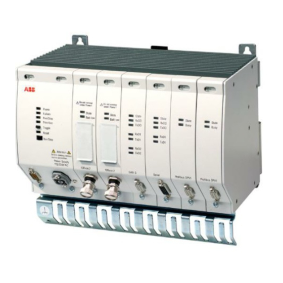
AC 800F System Overview AC 800F System Overview The AC 800F controller of the ABB Industrial IT series is compatible with all standard fieldbuses and is your key to the world of remote input/output. ABB's Operate IT product range includes the appropriate program - e.g. Control Builder F –which you can select according to your needs. -
Page 18: Fig. 1-1 Configuration Example: Ac 800F Integrated In The Freelance 2000 System
The CAN bus connects the central unit to the I/O units. It is used to transmit the input/output values from the AC 800F to the I/O modules. For this purpose, the AC 800F is equipped with CAN module FI 810F. - Page 19 Control Builder F engineering software has been installed. This manual describes how to mount, install and use the AC 800F. In most of the application and configuration examples given in this manual the AC 800F is integrated in the Freelance 2000 system.
-
Page 20: Fig. 1-2 Basic Ac 800F Configuration
AC 800F System Overview Figure 1-2 shows the setup of AC 800F in its most simple configuration: the AC 800F housing, one power supply module, one Ethernet module and one fieldbus module, without their connection cables. Fig. 1-2 Basic AC 800F configuration At present, the following AC 800F modules are available: •... - Page 21 CPU boards PM 802F and PM 803F. • Fieldbus modules FI 810F CAN module, 3 channels, available protocols:proprietary ABB CAN- Protocol for use with Freelance 2000 system (other protocols under preparation) FI 820F Serial module, 2 channels, available protocols: MODBUS, Sartorius...
-
Page 22: Fig. 1-3 Ac 800F With Five I/O Units
AC 800F System Overview The AC 800F fieldbus modules are driven by the CPU board in the AC 800F housing. The CPU board provides a similar computing capacity as the Freelance 2000 CPU module DCP 10. The data transmitted by the fieldbus modules is processed according to the configured function blocks and then transferred to the operator station via the Ethernet modules and the system bus. -
Page 23: Fig. 1-4 Profibus Dp Network, Example
Fig. 1-4 Profibus DP network, example Thanks to its Profibus module FI 830F, the AC 800F allows for convenient operation of Profibus DP fieldbus devices connected to it. Control Builder F is designed for easy commissioning of the Profibus DP fieldbus devices. -
Page 24: Fig. 1-5 Fieldbus Foundation H1 (Ffh1) Network, Example
AC 800F System Overview Figure 1-5 shows an AC 800F network based on the Fieldbus Foundation H1 which will be available with Version 6.2 and higher. Fig. 1-5 Fieldbus Foundation H1 (FFH1) network, example In the example shown above the Fieldbus Foundation H1 bus is connected to the Ethernet bus of the AC 800F via an external link device FIO 100. -
Page 25: Ac 800F Precautions
AC 800F Precautions AC 800F Precautions Do not soil with aggressive or conductive substances! Avoid electrostatic discharge to • contacts • the CPU board! Use a grounded wrist strap or touch the housing to discharge. Do not touch any parts inside the... - Page 26 AC 800F Precautions Touch the module front panel, only! Observe the max. ambient temperature! Avoid humidity condensing! Prior to first commissioning submit the modules to the specified operating temperature for a least 30 minutes and only then switch them Do not obstruct the air vents!
- Page 27 AC 800F Precautions Only hand-tighten the module screws! If bayonet locks are used lock by quarter turn. Fasten connectors and modules with screws. Observe the warnings!
-
Page 28: Routine Maintenance And Cleaning
AC 800F Precautions Routine maintenance and cleaning Clean dry ! Do not use moist or wet cloths! Cleaning interval: depending on dirt accumulation, e.g. weekly Do not use scratchy or sharp- edged tools for cleaning ! Observe the warnings! -
Page 29: Mounting The Ac 800F
Mounting the AC 800F Assembling the housing AC 800F is delivered as an already assembled basic unit, and with a pre-assembled power-supply module type SA 801F or SD 802F, as required. Only few mounting steps have to be carried out: additional modules have to be... -
Page 30: Dimensions And Mounting Depth
AC 800F dimensions without connected cables, connectors and strain relief/contact ledge. The AC 800F housing is 239 mm (9.4“ or 42 part units) wide and 161 mm (6.34“ or 3.6 HU) high, without contact ledge. The overall height with strain relief/contact ledge is 202 mm (7.95"... -
Page 31: Cabinet Or Switch Box Mounting
3.1.2 Cabinet or switch box mounting Two AC 800F can be mounted side by side without requiring a new frame or a modified cabinet. Figure 3-3 shows as an example how to mount a DRA 02 rack with a DPW 01 power supply of the Freelance 2000 system together with 2 AC 800F in a cabinet. - Page 32 Fig. 3-3 Cabinet mounting • Risk of overheating! Minimum spacing above and below AC 800F is 150 mm (3.375 HU). • Maximum temperature at the AC 800F bottom side (air intake): 60 ° ° ° ° C •...
-
Page 33: 3.1.2.1 Improved Air Circulation
Mounting the AC 800F 3.1.2.1 Improved air circulation Figure 3-4 shows the air flow in a cabinet with one Freelance 2000 rack and one AC 800F. The air flow passes through all racks heated while ascending. Fig. 3-4 Air flow without air deflectors... - Page 34 Mounting the AC 800F This unwanted stack effect can be avoided by using air deflectors DSU 65 (Fig. 3-5). Fig. 3-5 Air deflector DSU 65 Figure 3-6 shows the improved air circulation. Make sure that the cabinet is provided with the appropriate air inlets and outlets.
-
Page 35: Mounting On Top Hat Rails
When mounting the devices to top hat rails, make sure that they are positioned properly and that the rail clamping spring snaps Proceed as described below to mount the AC 800F to the top hat rail: • Hook AC 800F housing on top hat rail from above. -
Page 36: Wall Mounting On Top Hat Rails
• Risk of overheating ! Minimum spacing above and below: 150 mm (3.375 HU). • Max. temperature at the AC 800F bottom side (air intake): 60 ° ° ° ° C • Keep air vents open ! Do not impair air flow through AC 800F. -
Page 37: Vibration-Resistant Wall Mounting
The special mounting material RW 856F is available for applications where the AC 800F is run in an environment with strong vibration. Wall-mounting the AC 800F leaves enough space to mount other devices close to it without requiring additional material like mounting rails. -
Page 38: Grounding The Ac 800F
Mounting the AC 800F Grounding the AC 800F The AC 800F is a protection class II device. Therefore, no external grounding to protect against hazardous voltages is required. The AC 800F is provided with a functional grounding to drain off high-frequency interference. -
Page 39: Mounting The Modules
Use the power supply module SA 811F with software version 7.1 and higher for running a maximum of 4 Profibus modules FI 830F. Power supply module SA 801F is vital to AC 800F operation, since it delivers the necessary supply voltages to the CPU board, the Ethernet modules and the fieldbus modules. - Page 40 Mounting the AC 800F If the power supply is still on: • Do not unplug the connector ! The connector must not be used as an on/off switch. • Don’t undo the screws ! First switch off power ! •...
- Page 41 Mounting the AC 800F • Fasten power supply module at the top and at the bottom. Slightly push in the module screws using a screw driver and turn clockwise. Only hand- tighten the screws. • Alternatively, bayonet locks available. When...
-
Page 42: Mounting Power Supply Module Sa 811F
At present, the power supply module SA 811F can be run with CPU board PM 803F only with software version 7.1 or higher. Power supply module SA 811F is vital to AC 800F operation, since it delivers the necessary supply voltages to the CPU board, the Ethernet modules and the fieldbus modules. - Page 43 Mounting the AC 800F If the power supply is still on: • Do not unplug the connector ! The connector must not be used as an on/off switch. • Don’t undo the screws ! First switch off power ! •...
- Page 44 Mounting the AC 800F • Fasten power supply module at the top and at the bottom. Slightly push in the module screws using a screw driver and turn clockwise. Only hand- tighten the screws. • Alternatively, bayonet locks available. When using...
-
Page 45: Mounting Power Supply Module Sd 802F
Use the power supply module SA 812F with software version 7.1 and higher for running a maximum of 4 Profibus modules FI 830F. Power supply module SD 802F is vital to AC 800F operation, since it delivers the necessary supply voltages to the CPU board, the Ethernet modules and the fieldbus modules. - Page 46 Mounting the AC 800F If the power supply is still on: • Do not unplug the connector ! The connector must not be used as an on/off switch. • Don’t undo the screws ! First switch off power ! •...
- Page 47 Mounting the AC 800F • Fasten power supply module at the top and at the bottom. Slightly push in the module screws using a screw driver and turn clockwise. Only hand- tighten the screws. • Alternatively, bayonet locks are available. When using such...
-
Page 48: Mounting Power Supply Module Sd 812F
At present, the power supply module SA 812F can be run with CPU board PM 803F only with software version 7.1 or higher. Power supply module SD 812F is vital to AC 800F operation, since it delivers the necessary supply voltages to the CPU board, the Ethernet modules and the fieldbus modules. - Page 49 Mounting the AC 800F If the power supply is still on: • Do not unplug the connector ! The connector must not be used as an on/off switch. • Don’t undo the screws ! First switch off power ! •...
- Page 50 Mounting the AC 800F • Fasten power supply module at the top and at the bottom. Slightly push in the module screws using a screw driver and turn clockwise. Only hand- tighten the screws. • Alternatively, bayonet locks are available. When using such...
-
Page 51: Mmounting Ethernet Modules
Mounting the AC 800F 3.3.5 Mounting Ethernet modules The Ethernet modules EI 801F, EI 802F and EI 803F and EI 811F, EI 812F and EI 813F are used to establish a communication link with the operator station level via the system bus. The term Ethernet represents LANs to DIN ISO 8802, Part 3 (corresponding to ISO 8802-3 and ANSI/IEEE STD 802.3). - Page 52 Mounting the AC 800F The following Ethernet modules are available for use with CPU board PM 803F with software version 7.1 and higher: • 10Base2 module EI 811F The 10Base2 standard (Cheapernet) is based on a thin coax. cable (type RG58U).
-
Page 53: Fig. 3-11 Ethernet Module Coding Switch
Refer to Section 4.2.4 for details. Plug Ethernet modules in E-slots, only! The AC 800F slots are subdivided into the following groups: P (Power), E (Ethernet) and F (fieldbus modules). Plug the Ethernet modules in slot(s) E1 and/or E2. -
Page 54: Fig. 3-12 Adjusting Ip Address
Set the coding switch of the first AC 800F to 1, and increase by one for each additional AC 800F. From the tenth AC 800F on use A ... E. Do not use 0 and F. What is stated above does not apply to coding switch positions 0 and F! Position 0 is described below, position F is reserved for operation in redundancy mode. -
Page 55: Fig. 3-13 Standard Setting
Control Builder F. Then the data exchange will take place via write and read utilities. The time will be synchronized for all AC 800F and process stations, independent of the system to which they belong. Fig. 3-13... -
Page 56: Fig. 3-14 Special Setting
Fig. 3-14 Special setting In the commissioning phase of the AC 800F, an individual IP address has to be set for every station on the system bus. Refer to Section 5.4 for details. Contact your network administrator for these IP addresses. -
Page 57: Fig. 3-15 Redundancy Case, Standard Setting
The second Ethernet module (slot E2) is connected to the redundant AC 800F. In this case, the coding switch on the Ethernet module must be set to position F. -
Page 58: Fig. 3-16 Redundancy Case, Special Setting
Fig. 3-16 Redundancy case, special setting In the commissioning phase of the AC 800F, an individual IP address has to be set for every station on the system bus. Refer to Section 5.4 for details. Contact your network administrator for these IP addresses. - Page 59 Mounting the AC 800F • Insert the Ethernet module into the guiding grooves of slot E1 or E2 and slide it in. • Fasten the Ethernet module at the top and at the bottom. Slightly push in the module screws using a screw driver and turn clockwise.
-
Page 60: Mounting Fieldbus Modules
Mounting the AC 800F 3.3.6 Mounting fieldbus modules The following fieldbus modules can be mounted in the AC 800F: • CAN module FI 810F for connecting intelligent field instruments with a CAN interface; the module provides three CAN interfaces and, thus, ensures compatibility with the Freelance 2000 process station. - Page 61 Mounting the AC 800F • Profibus module FI 830F a Profibus DP master in accordance with DIN 19245/ EN 50170, suitable for rapid data exchange manufacturing, where decentralized peripherals (DP) are used. • FF/HSE module FI 840F high-speed Ethernet module...
- Page 62 Mounting the AC 800F • Insert the fieldbus module into the guiding grooves of slot F1 ... F4 and slide it in. • Fasten fieldbus module at the top and at the bottom. Slightly push in the module screws using a screw driver and turn clockwise.
-
Page 63: Covering Empty Slots With Caps (Dummy Panels)
Mounting the AC 800F 3.3.7 Covering empty slots with caps (dummy panels) Always cover empty (unused) slots with dummy panels AM 895F. They protect internal boards from being touched and provide for good RFI suppression and EMI/RFI shielding capabilities (EMC). -
Page 64: Putting On Cable Shields
(RW 855F). Use the same mounting material. Although it is possible to use the AC 800F with unshielded cables, it is recommended to use shielded ones. Otherwise, the EMI/RFI shielding capabilities and signal/noise ratios specified for these operating conditions cannot be guaranteed. -
Page 65: Fig. 3-17 Applying The Communication Cable
Mounting the AC 800F Strip off the cable sheath around 5 cm below the connector on a length of 2 cm, as seen in Fig. 3-17. Use one of the available clips TV 831F and TV 832F for strain relief and for putting on the cable shield. -
Page 66: Mounting Ac 800F
Mounting the AC 800F 3-38... -
Page 67: Cabling The Ac 800F
115 - 230 V AC mains. • Prior to applying the mains voltage to it, always plug the power supply module into the AC 800F and fasten it with screws. Otherwise, live high voltage parts will be exposed and might be touched by the operator. -
Page 68: Fig. 4-2 Laying Cables Of Power Supply Module Sa 801F
• Provide a functional grounding as described in Section 3.2. • When using the AC 800F on a 115 - 230 V AC mains, make sure that it is equipped with a SA 801F power supply module. • Lay the mains cable separately (not too close to communication cables), as seen in the following illustration. -
Page 69: Power Supply Module Sa 811F (115 - 230 V Ac)
115 - 230 V AC mains. • Prior to applying the mains voltage to it, always plug the power supply module into the AC 800F and fasten it with screws. Otherwise, live high voltage parts will be exposed and might be touched by the operator. -
Page 70: Fig. 4-4 Laying Cables Of Power Supply Module Sa 811F
• Provide a functional grounding as described in Section 3.2. • When using the AC 800F on a 115 - 230 V AC mains, make sure that it is equipped with a SA 811F power supply module. • Lay the mains cable separately (not too close to communication cables), as seen in the following illustration. -
Page 71: Power Supply Module Sd 802F (24 V Dc)
• Prior to applying the mains voltage to it, always plug the power supply module into the AC 800F and fasten it with screws. • Do not connect power supply module to 115 - 230 V AC. Otherwise, it will be damaged or even destroyed. -
Page 72: Fig. 4-6 Laying Cables Of Power Supply Module Sd 802F
Cabling the AC 800F When installing power supply module SD 802F, observe the following rules: • The power supply module has no mains switch, provide one for each supply (standard and redundant). • It is recommended to use a 4 AT fuse to IEC/EN 60127-2/V, ceramic cartridge 5 x 20 mm, high breaking capacity, melt index of at least 22 A s e.g. -
Page 73: Power Supply Module Sd 812F (24 V Dc)
• Prior to applying the mains voltage to it, always plug the power supply module into the AC 800F and fasten it with screws. • Do not connect power supply module to 115 - 230 V AC. Otherwise, it will be damaged or even destroyed. -
Page 74: Fig. 4-8 Laying Cables Of Power Supply Module Sd 812F
Cabling the AC 800F When installing power supply module SD 812F, observe the following rules: • The power supply module has no mains switch, provide one for each supply (standard and redundant). • It is recommended to use a 4 AT fuse to IEC/EN 60127-2/V, ceramic cartridge 5 x 20 mm, high breaking capacity, melt index of at least 22 A s e.g. -
Page 75: Connection Via Rs232 Interface For Diagnosis
PC. Please refer to Section 5.4, Diagnosing the AC 800F for more detailed information. The AC 800F is supplied with a functional extra low voltage with protective separation from other circuits. Note that connecting a diagnostic PC or... -
Page 76: Cabling Ethernet Modules
AC 800F integrated into them. The following explanations apply to both the system bus and the redundant communication bus. The system bus of the AC 800F is based upon the widespread Ethernet standard. “Ethernet” stands for LANs to DIN ISO 8802, Part 3 (corresponding to ISO 8802-3 and ANSI/IEEE STD 802.3). -
Page 77: 10Base2 (Cheapernet, Thin Ethernet)
Cabling the AC 800F 4.2.1 10Base2 (Cheapernet, Thin Ethernet) Topology bus topology, branches with transceivers and AUI cables coaxial cable 50 Ω, Transmission medium two 50 Ω terminating resistors Transmission base band, data rate 10 MBit/s Maximum segment length 185 m... -
Page 78: 10Base5 (Full Ethernet)
Cabling the AC 800F 4.2.2 10Base5 (Full Ethernet) Topology bus topology; branches (AUI cables) possible. coaxial cable 50 Ω (Yellow Cable) Transmission medium two 50 Ω terminating resistors Transmission base band, data rate 10 MBit/s Maximum segment length 500 m... -
Page 79: 10Baset (Full Ethernet)
Cabling the AC 800F 4.2.3 10BaseT (Full Ethernet) Contrary to 10Base2 and 10Base5 networks, 10BaseT networks have a star topology instead of a bus topology. Twisted-pair cables are used for data transmission. Topology star topology, connection via hubs or star couplers... -
Page 80: 100Baset Or Ff/Hse (Full Ethernet)
Cabling the AC 800F 4.2.4 100BaseT or FF/HSE (Full Ethernet) Contrary to other fieldbus systems the 100BaseT or FF/HSE networks have a star topology instead of a bus topology. Twisted-pair cables are used for data transmission. Topology star topology, connection via hubs or... -
Page 81: 10Basefl
Cabling the AC 800F 4.2.5 10BaseFL This standard uses a star topology as well. Fiber optic cables are the transmission medium used here. The maximum length of a fiber optic cable link is 4 km. Transmission is done in the base band with a data rate of 10 MBit/s. - Page 82 Cabling the AC 800F Applications: • Networks within one building or between buildings • Installations with high EMI • Network cables close to power cables • Areas with high potential differences • Large installations • Installations where a protective separation by the network is required •...
-
Page 83: Designing The Network
For details refer to Section 4.2.10.5. If you don’t have any experience in designing and installing LANs please contact an expert. For details on how to design a network refer to • ABB: Design and components of CSO networks, Technical Bulletin 30/72-6211-EN. 4-17... -
Page 84: 4.2.6.2 Acceptance Measurement
(e.g. due to kinks or breaks). Fiber optic cables should not only be submitted to an OTDR measurement, but also to an attenuation measurement. This is especially important after splicing works at the cable. ABB Service can be engaged to perform the acceptance measurements. 4-18... -
Page 85: Installing A 10Base2 Network (Cheapernet)
Cabling the AC 800F 4.2.7 Installing a 10Base2 network (Cheapernet) 4.2.7.1 General This section describes the installation of a single 10Base2 segment. When installing several segments also refer to Sections 4.2.11 and 4.2.12. Operation of a 10Base2 network requires that a 10Base2 module is plugged in slot E1... -
Page 86: 4.2.7.2 Cabling A 10Base2 Segment
Cabling the AC 800F 4.2.7.2 Cabling a 10Base2 segment The following components are needed for cabling a 10Base2 segment with n nodes: 10Base2 terminating resistor dual package 10Base2 F-connector, 10Base2 Y-connector or 10Base2 T-connector All connectors have the same function. However, only 10Base2 F-connectors can be used with 10Base2 module. -
Page 87: Fig. 4-11 10Base2 Cabling With 3 Nodes
Observe the safety regulations and standards applicable in your country. The AC 800F has a contact ledge for putting on cable shields. It is located under the plug-in modules. In 10Base2 cables the shield is also used as one of the signal lines. -
Page 88: 4.2.7.3 Connecting 10Base2 Nodes While The System Is Running
Cabling the AC 800F Connect the 10Base2 cable to ground on the 10Base2 module of every AC 800F, as shown in Figure 4-12. Protect the unsheathed metallic 10Base2 F-connectors and 10Base2 cable connectors from any contact with ground or conductive parts of the building, e.g. by using an insulating sleeve. -
Page 89: Fig. 4-13 10Base2 Connection Via Junction Boxes
Cabling the AC 800F Insulate 10Base2 F- connector to avoid contact with ground or conductive parts of the building. To connect the engineering station proceed in reverse order. The disadvantage of this method is that the disconnected 10Base2 F-connector must not have any contact with ground or any conductive parts of the building. -
Page 90: Fig. 4-14 10Base2 Connection Via Transceiver
Cabling the AC 800F Connection via transceiver This network connection should be used if you need branch cables from a 10Base2 cable or if an engineering station is to be connected alternately to 10Base2 and 10Base5 networks. You work with the AUI interface, independently of the network type. -
Page 91: 4.2.7.4 Crimping 10Base2 Cables
Cabling the AC 800F 4.2.7.4 Crimping 10Base2 cables Ready-made cables with a maximum length of 185 m are available for 10Base2 networks. If it is necessary to shorten or repair a cable while installing, all necessary parts can be found in a 10Base2 mounting tool kit. 10Base2 cable connectors can be ordered separately. -
Page 92: Installing A 10Base5 Network (Yellow Cable)
Cabling the AC 800F 4.2.8 Installing a 10Base5 network (Yellow Cable) 4.2.8.1 General This section describes the installation of a single 10Base5 segment. Operation with a 10Base5 network requires that an AUI module is plugged in slot E1 or E2. A 10Base5 cable should be used in the following cases:... -
Page 93: 4.2.8.2 Linking 10Base5 Cable Segments
Cabling the AC 800F 4.2.8.2 Linking 10Base5 cable segments Several short 10Base5 cable segments can be linked by 10Base5 N/N connectors until reaching the maximum length. The following standardized 10Base5 network cable lengths are available: • • • 23,4 m... -
Page 94: 4.2.8.3 Cabling A 10Base5 Segment
Cabling the AC 800F 4.2.8.3 Cabling a 10Base5 segment The following components are needed for cabling a 10Base5 segment with n nodes: 10Base5 terminating resistors with external thread for network concentrator or with internal thread for cable Grounding clip 10Base5 cable... -
Page 95: Fig. 4-16 Cabling A 10Base5 Network With 3 Nodes
Cabling the AC 800F Example: The following components are needed for a network with 3 nodes 10Base5 cable 10Base5 terminating resistors Grounding clip 10Base5/AUI transceivers AUI cables clips TV 83xF Cable as shown below: Fig. 4-16 Cabling a 10Base5 network with 3 nodes... - Page 96 Cabling the AC 800F When cabling proceed as follows: Lay the bus cable • Do not lay the cable close to power cables • Screw the terminating resistors to both cable ends • Note that the min. bending radius of the 10Base5 cable is 15 cm.
- Page 97 Cabling the AC 800F Mounting a 10Base5 tap (Vampire tap) with transceiver Material Determine tap position Only attach transceivers at the marks. The spacing between two marks is 2.5 m. Insert the shield taps in the body. Lay the cable in the slot of the body.
- Page 98 Cabling the AC 800F Fasten screw with Allan key until the clip fits tightly to the cable. Remove protective cap. Use the drill of the 10Base5 mounting tool kit to drill a hole in the cable down to the internal conductor.
- Page 99 Cabling the AC 800F Only if cable is not yet live Check contact with ohmmeter. Measure resistance between contact piece and shield tap. With two terminating resistors the measured resistance should be 25 Ω Ω Ω Ω . Error : Resistance = ∞...
-
Page 100: 4.2.8.4 Connecting And Disconnecting Nodes While The System Is Running
Make sure that the AUI module lock at the front snaps in. Use grounding clip TV 83xF to ground the AUI cable of the AC 800F on the contact ledge. Proceed as shown in Figure 4-17. -
Page 101: Installing A 10Baset (Twisted Pair) Network
Cabling the AC 800F 4.2.9 Installing a 10BaseT (twisted pair) network 4.2.9.1 General This section describes how to install a single 10BaseT segment. A 10BaseT network requires that a 10BaseT module is present in slot E1 and/or slot Maximum segment length... -
Page 102: Fig. 4-19 Cabling A 10Baset Network With 4 Nodes
10BaseT hubs are available with a different number of ports and as rail-mounting units, 19“ rack-mounting units, or desktop units. The cables and hubs are still under preparation. Please contact your ABB customer service if you should need more information about 10BaseT cables, hubs or star couplers. -
Page 103: Fig. 4-20 Cabling A 10Baset Network With 3 Nodes
Cabling the AC 800F Often a network already existing in the building is integrated in the new network. In this case, the appropriate 10BaseT installation sockets are already available in the room. You simply have to connect your network to theses sockets. -
Page 104: Installing A 10Basefl Network (Fiber Optic Cable)
This manual refers to network concentrator type, a 9.5 inch device (width) for 115/230 V. All other models can be used as well. There are two ways to connect to slot E1 or E2 of the AC 800F: • via a 10BaseFL transceiver to an AUI module or •... - Page 105 Cabling the AC 800F Fiber optic cables are used for: • Long distance links • Links between buildings • Installations with high EMI • Links close to power cables • Areas with high potential differences • Large installations • Installations where a protective separation by the network is required •...
-
Page 106: 4.2.10.2 Cabling Via 10Basefl Transceivers
Cabling the AC 800F 4.2.10.2 Cabling via 10BaseFL transceivers The following components are needed for a network with up to 9 nodes: Network concentrator with 5/9 slots incl. 230/115 V power supply and power cable 10BaseFL cable 10BaseFL module 10BaseFL transceiver... -
Page 107: Fig. 4-22 Cabling A 10Basefl Network With 3 Nodes
Ground every AUI cable shield as described in Section 4.2.8.3. If the available mounting depth permits you can also plug the 10BaseFL transceivers directly to the AUI module of the AC 800F. In this case no AUI cables are needed. -
Page 108: Fig. 4-23 10Basefl Cable Link
Connect the AUI cable side provided with a slide lock to the transceiver and lock. Connect the other cable side to the AC 800F AUI module and lock, too. Make sure that that the slide lock on the AUI module front panel snaps in properly. -
Page 109: 4.2.10.3 Long-Distance Links Within Buildings
Splicing is a welding operation which must be carried out by qualified personnel, only. Contact the ABB service for splicing works. Splicing pig-tails is easier than mounting connectors to the middle piece on site. Therefore, splicing should be preferred. Make sure that the splice points meet the quality requirements by measuring/testing the whole link on site and noting down the results in an acceptance record. -
Page 110: 4.2.10.4 Links Between Buildings
Cabling the AC 800F The splice box is a special housing for protecting the splice point and winding up the surplus cable length. If the boxes have to meet special requirements for your application - e.g. mounting in 19“ cabinets or integration of routers please contact us for more information. -
Page 111: 4.2.10.5 Redundant 10Basefl Cable Link
Cabling the AC 800F 4.2.10.5 Redundant 10BaseFL cable link In order to meet higher system bus availability requirements, redundant fiber optic cable links can be laid between the network concentrators. In this case it also recommended to use network concentrators with redundant power supplies. The... - Page 112 Cabling the AC 800F Example for two nodes: network concentrators, 10/19 slots, with redundant power supply 10BaseFL modules AUI modules AUI cables 10BaseFL cables clip TV 83xF Cable the components as shown in Fig. 4-25. Fig. 4-25 Redundant 10BaseFL cabling, case 1 Configure one of the two 10BaseFL modules for redundant operation by setting the jumper accordingly.
- Page 113 Cabling the AC 800F It is recommended to keep the link between the AC 800F or operator station and the network concentrator as short as possible in this case. This reduces the risk that the non-redundant link between the network concentrator and the AC 800F or operator station fails.
-
Page 114: 4.2.10.6 Protective Separation Via 10Basefl
There are two ways to achieve protective separation of the operator and engineering stations and the AC 800F, which will be described below. Note that the power supply modules SA 801F/SA 811F of the AC 800F are provided with a protective separation. -
Page 115: Fig. 4-28 Protective Separation Via Ethernet, 2Nd Way
Since the network concentrator uses the same 10Base2 cable as the AC 800F, it must be a 24 V unit, the 24 V supply of which must have a protective separation as well. -
Page 116: 4.2.10.7 Max. Permissible Network Length With 10Basefl Cable
Cabling the AC 800F 4.2.10.7 Max. permissible network length with 10BaseFL cable The explanations in this section give only a short overview. Observe the detailed information about how to design fiber optic cable networks given in Hirschmann GmbH & Co, Esslingen: Ethernet Manual,... -
Page 117: Fig. 4-29 Propagation Delay Calculation For An Installation, Example
Fig. 4-29 Propagation delay calculation for an installation, example In Fig. 4-29 the longest signal path is from AC 800F 1 over AC 800F 2 to AC 800F 3, via the 10Base5 concentrator module, the 10BaseFL concentrator module, the 10BaseFL cable, the 10BaseFL transceiver, and the AUI cable to the operator station. - Page 118 Cabling the AC 800F The following table shows this calculation. Cable of length or component Cable length 10Base2 cable, length 10 m 10 m 10Base2 cable, length 15 m 15 m 10Base2 cable, length 50 m 50 m 10Base5 concentrator module...
-
Page 119: Mixed Networks
Figure 4-30 shows an example for a mixed network: Fig. 4-30 Mixed network Two 10BaseFL cables (fiber optic cables) link the AC 800F with the network concentrator. The fiber optic cables can be used for long distances and in environments with high EMI. -
Page 120: Coupling Cable Segments Via Repeaters
Cabling the AC 800F 4.2.12 Coupling cable segments via repeaters For some applications more than one cable segment is needed. In these cases, cable segments can be coupled via repeaters. This is especially required if existing networks are expanded at a later time. -
Page 121: Fig. 4-32 Large System With Max. Possible Transmission Distances
Cabling the AC 800F Figure 4-32 shows a large system with repeaters and max. possible transmission distances as an example. Fig. 4-32 Large system with max. possible transmission distances The following rules must be observed when using repeaters: • The number of repeaters between two nodes is limited to four. -
Page 122: Cabling Ac 800F For Operation In Redundancy Mode
4.2.13 Cabling AC 800F for operation in redundancy mode Two AC 800F can be linked to enable operation in redundancy mode. In addition to the Ethernet module in slot E1 for normal network communication a second Ethernet module is present in slot E2. A point-to-point connection called the ‘redundancy link’ is set up between the Ethernet modules in the E2 slots of the two AC 800F. -
Page 123: Cabling The Fieldbus Modules
Cabling the AC 800F Cabling the fieldbus modules 4.3.1 Cabling Profibus module FI 830F When using the power supply module SA 801F or SD 802F together with the CPU board PM 803F, a maximum of 3 Profibus modules FI 830F can be supported. -
Page 124: 4.3.1.1 Connecting The Profibus Via Rs485
Cabling the AC 800F Signal Description shield shield n. c. not used RxD+/TxD+ receive / transmit data - PLUS repeater control signal (direction control) data transmission potential (ground to 5 V) 5 V supply voltage of terminating resistors n. c. -
Page 125: Fig. 4-35 Profibus Connector, Internal Circuitry
Cabling the AC 800F impedances reduce line reflections normally occurring at each connection point. series impedances matched with the line parameters Profibus cable connected. Fig. 4-35 Profibus connector, internal circuitry The bus cable to be used for the bus module is specified in DIN 19245/EN 50170 as... -
Page 126: Fig. 4-36 Cabling Fi 830F
Cabling the AC 800F When connecting the nodes make sure that the data lines are not distorted or confounded. RxD/TxD-P signal wire connected to pin 3 of the Profibus module connector must connected to the relevant signal wires with the same designation of all nodes. -
Page 127: Fig. 4-38 Grounding Fi 830F
Cabling the AC 800F Preparing a Profibus cable • Cut the Profibus cable type A to the required lengths. Strip off the insulation from the cable ends. • Observe the manufacturer instructions for the Profibus connector. • Make sure not to confound feed and return wires. The incoming and outgoing signals must not be applied to the same pin. -
Page 128: Connecting The Profibus Via Fiber-Optic Cables (Fo Cables)
Cabling the AC 800F To ensure RFI suppression in accordance with Class DIN/VDE install the ferrite ring RFI suppressor from Würth-Elektronik, ordering code 742 701 110. The requirements of RFI suppression Class A are always met. Fig. 4-39 Profibus connector with ferrite-type RFI... - Page 129 Cabling the AC 800F The Profibus on FO basis is preferably used for: • Long distance links • Links between buildings • Installations with high EMI • Links close to power cables • Areas with high potential differences • Large installations •...
-
Page 130: 4.3.1.3 Connecting A Profibus Master Redundancy
Observe the instructions given above for connecting a Profibus via RS485. The process data on the primary (i.e. active) AC 800F are permanently matched with those on the secondary (i.e. redundant) AC 800F via the redundancy link. For this purpose, a point-to-point connection is established between the two redundant AC 800F. - Page 131 Cabling the AC 800F Features of the Redundancy Link Module RLM 01: • Conversion: line M lines A/B • For use on Profibus DP/FMS lines • Automatic line selection • Transmission rate 9.6 kbauds ..12 Mbauds • Communication monitoring •...
-
Page 132: Fig. 4-42 Line Redundancy
A, B and M, observe the installation instructions for normal (not redundant) Profibus cabling. Fig. 4-42 Line redundancy For details about Profibus DP technology, redundancy and installation and the RLM 01 module please contact your ABB customer service. 4-66... -
Page 133: 4.3.1.5 Connecting Profibus-Pa Nodes
Cabling the AC 800F 4.3.1.5 Connecting Profibus-PA nodes The Profibus module FI 830F is designed exclusively for the connection of Profibus- DP nodes. If you intend to integrate a Profibus-PA line - i.e. several PA nodes - into the network, it is recommended to use a linking device LD 800P. The linking device converts the DP bus physics to PA bus physics. -
Page 134: Fig. 4-44 Connection Diagram Ld 800P
Cabling the AC 800F Functional description of LD 800P The RS485 interface of the LD 800P link device (Profibus DP) supports all baud rates up to 12 Mbauds specified for Profibus DP in DIN 19245/ EN 50170. The baud rates are software-configurable. -
Page 135: Fig.4-45
This link is used for cyclic alignment. Fig.4-45 Connection diagram for redundancy operation with LD 800P For detailed technical information about the Profibus linking device LD 800P please contact your ABB customer service center. 4-69... -
Page 136: Cabling The Serial Fieldbus Module Fi 820F
Cabling the AC 800F 4.3.2 Cabling the serial fieldbus module FI 820F The serial fieldbus module FI 820F has two serial communication channels. The channels can be used as RS232, RS422 or RS485 interfaces, as required. The signals from each of the three interface types are applied to different pins of the 26-pin connector. -
Page 137: Fig. 4-47 Fi 820F Internal Termination
Cabling the AC 800F Internal termination Fig. 4-47 FI 820F internal termination Cable TK 821F and terminal block TB 870F Fig. 4-48 CAN cable TK 821F with terminal block TB 870F The terminal block is designed for mounting on top hat rails. It has the following... -
Page 138: 4.3.2.1 Connection Via Rs232 Interface
Link module FI 820F with the terminal block TB 870F using cable TK 821F. Only hand-tighten the screws. • Put on the TK 821F cable shield. Connect it to the AC 800F contact ledge using a clip TV 83xF. •... -
Page 139: Fig
Cabling the AC 800F Channel 0 on terminal block TB 870F Transmit data (Output) Pin 2 Receive data (Input) Pin 1 Ground Pin 5 Request to send (Output) Pin 4 Clear to send (Input) Pin 3 Channel 1 on terminal block TB 870F... -
Page 140: 4.3.2.2 Connection Via Rs422 Interface
Connect the serial fieldbus module FI 820F to the terminal block TB 870F using cable TK 821F. Only hand-tighten the screws. • Put on the TK 821F cable shield. Connect it to the AC 800F contact ledge using clip TV 83xF. •... - Page 141 Fig. 4-50 Cabling FI 820F via RS422 interface on channel 0 Terminate the two signal pairs on the AC 800F side and on the device to be connected. There are three possible terminations on the AC 800F side: •...
-
Page 142: Fig. 4-51 Internal Rs422 Termination Of Fi 820F
Cabling the AC 800F Internal termination Fig. 4-51 Internal RS422 termination of FI 820F When touching the terminating jumpers take the necessary ESD protection measures. Follow the instructions given in Section 2. External termination with internal supply Fig. 4-52 Activating the termination on the terminal block TB 870F When using the terminating voltage of the module, the bus is not terminated properly when the module is switched off or replaced. -
Page 143: Fig. 4-53 External Termination With External Supply
Cabling the AC 800F External termination with external supply Fig. 4-53 External termination with external supply Fig. 4-54 Terminating voltage from external 5 V power supply Use an external power supply with protective separation! 4-77... -
Page 144: 4.3.2.3 Connection Via Rs485 Interface
Connect the serial fieldbus module FI 820F with the terminal block TB 870F using cable TK 821F. Only hand-tighten the screws. • Put on the TK 821F cable shield. Connect it to the AC 800F contact ledge using a clip TV 83xF. •... -
Page 145: Cabling Fi 820F Via Rs485 Interface, Case 1
Fig. 4-55 Cabling FI 820F via RS485 interface, case 1 Terminate the two signal pairs on the AC 800F side and on the device to be connected. There are three possible terminations on the AC 800F side: •... -
Page 146: Fig. 4-56 Internal Rs485 Termination
Cabling the AC 800F Internal termination Fig. 4-56 Internal RS485 termination When touching the terminating jumpers take the necessary ESD protection measures. Follow the instructions given in Section 2. External termination with internal supply Fig. 4-57 Activating the termination on the terminal block TB 870F When using the terminating voltage of the module, the bus is not terminated properly when the module is switched off or replaced. -
Page 147: Fig. 4-58 External Termination With External Supply
Cabling the AC 800F External termination with external supply Fig. 4-58 External termination with external supply Fig. 4-59 Terminating voltage from external 5 V power supply Use an external power supply with protective separation! 4-81... - Page 148 Cabling the AC 800F 2. FI 820F not installed at the end of the bus cable. Cable the terminal block TB 870F with the other RS485 nodes on the bus as seen in Fig. 4-60. Keep the branch cables to the nodes as short as possible.
-
Page 149: Redundant Cabling Of Two Serial Fieldbus Modules
Link two redundant fieldbus modules with the terminal block TB 870F using cable TK 821F. Only hand-tighten the screws. • Put on the TK 821F cable shields. Connect them to the two AC 800F contact ledges using clips TV 83xF. •... -
Page 150: 4.3.3.2 Redundant Connection Via Rs422 Interface
Link two redundant fieldbus modules FI 820F with the terminal block TB 870F using cable TK 821F. Only hand-tighten the screws. • Put on the TK 821F cable shields. Connect them to the two AC 800F contact ledges using clips TV 83xF. •... - Page 151 If the shield is not put on properly, neither RFI suppression nor EMI/RFI shielding of the system can be guaranteed. Fig. 4-62 shows redundant cabling of two AC 800F with one serial fieldbus module each, using channel 0. Connect the external power supply, as seen in Fig. 4-59.
-
Page 152: 4.3.3.3 Redundant Connection Via Rs485 Interface
Link two redundant modules FI 820F with the terminal block TB 870F using cable TK 821F. Only hand-tighten the screws. • Put on the TK 821F cable shields. Connect them to the two AC 800F contact ledges using clips TV 83xF. •... -
Page 153: Fig. 4-63 Redundant Cabling Of Fi 820F Via Rs485 Interface
Make sure that no jumpers are set on the fieldbus modules FI 820F and that the switches on the internal terminal block TB 870F are in the OFF position. In the example described above it is assumed that an AC 800F is connected to the end of the bus cable. 4-87... - Page 154 Cabling the AC 800F If the two redundant AC 800F are not located at the end of the bus cable, proceed as seen in Fig. 4-60. Follow the instructions below: • Deactivate the internal termination of the serial fieldbus modules.
-
Page 155: Cabling Can Module Fi 810F
TB 870F. If the AC 800F is located at the end of the bus cable and the internal termination is used, the DSU 07 or DSU 011 cables can be connected directly. Note that the distance relevant for selecting the appropriate cable type is not given by the individual cable lengths. -
Page 156: Fig
Cabling the AC 800F Internal termination Fig. 4-65 Internal termination of FI 810F, channels 0, 1 and 2 Fig. 4-66 CAN cable TK 811F Fig. 4-67 CAN cable DSU 11 Fig. 4-68 CAN cable TK 817F Fig. 4-69 CAN cable DSU 07... -
Page 157: Fig. 4-70 Can Cable Tk 831F With Terminal Block Tb 870F
Cabling the AC 800F Cable TK 831F with terminal block TB 870F Fig. 4-70 CAN cable TK 831F with terminal block TB 870F Terminal block TB 870F is designed for mounting on top hat rails and has the following dimensions:... - Page 158 I/O in or I/O out of the link modules DLM 01 and DLM 02. If the AC 800F is located at the end of a bus, you can make either an internal termination, or an external termination on the terminal block TB 870F. The advantage of the internal termination is that the CAN cable DSU 07 or DSU 011 can be connected directly and without requiring a terminal block TB 870F.
-
Page 159: Fig. 4-71 Can Bus Connection Example, With Internal Termination
Cabling the AC 800F Connection example: AC 800F with I/O units and internal termination Fig. 4-71 CAN bus connection example, with internal termination Fig. 4-72 FI 810F internal termination, channels 0, 1 and 2 When touching the terminating jumpers take the necessary ESD protection measures. -
Page 160: Fig. 4-73 Can Bus Connection Example, With External Termination
Cabling the AC 800F Connection example: AC 800F with I/O units and external termination Fig. 4-73 CAN bus connection example, with external termination With external termination always use terminals 14, 15, 17, 18, 20 and If the I/O units are connected to terminals 1, 2, 4, 5, 7 and 8, the CAN bus is not terminated properly at its ends. -
Page 161: Redundant Cabling Of Two Can Modules Fi 810F
Link two redundant CAN modules with the terminal block TB 870F using cable TK 831F. Only hand-tighten the screws. • Put on the TK 831F cable shields. Connect them to the two AC 800F contact ledges using clips TV 83xF •... -
Page 162: Redundant Connection Of The Can Bus, Case 1
Cabling the AC 800F Fig. 4-75 shows the redundant cabling of two AC 800F with one CAN module FI 810F at each end of the bus cable. Fig. 4-75 Redundant connection of the CAN bus, case 1 Terminate the individual components as seen in the illustration. - Page 163 In the scenarios shown in the two illustrations above it is assumed that one A 800F is connected to the end of the bus. If none of the two redundant AC 800F is connected to the end of the bus cable, follow the instructions below: •...
-
Page 164: Fig. 4-78 External Termination For Redundant Cabling
Cabling the AC 800F Fig. 4-77 Redundant cabling of the CAN bus, case 2 Terminate the individual components as seen in the illustration below: Fig. 4-78 External termination for redundant cabling • Do not set the jumpers on the FI 810 F modules! •... -
Page 165: Cabling The Ff/Hse Module Fi 840F
Cabling the AC 800F 4.3.6 Cabling the FF/HSE module FI 840F The FieldbusFoundation/HSE module FI 840F is a fieldbus module with twisted-pair Ethernet bus physics. This ensures that all 100BaseT network components available on the market can also be used with the FieldbusFoundation/HSE fieldbus module FI 840F. -
Page 166: 4.3.6.1 Cabling Ff/Hse Or 100Baset
100BaseT hubs are available for rail mounting, as 19" rack mounting units, and as desktop units, with a different number of ports. Suggestions for the cables and hubs are still under preparation. Please contact you ABB customer support center for details about 100BaseT cables, hubs and star couplers. -
Page 167: Fig. 4-80 100Baset Network With 4 Nodes
Cabling the AC 800F Example: The following components are needed for a network with four nodes: 100BaseT cable, uncrossed 100BaseT hub (4-fold) Fig. 4-80 100BaseT network with 4 nodes Follow the instructions below: • Use the appropriate cable type: cross cable for direct connection of two nodes, uncrossed cable when additionally using a hub. - Page 168 Cabling the AC 800F 4-102...
-
Page 169: Ac 800F Functional Description
The power supply modules SA 801F, SA 811F, SD 802F and SD 812F power the AC 800F CPU board and all modules plugged in its slots E1, E2 and F1 ... F4. The power supply modules SA 811F and SD 812F have an increased output power as compared to the SA 801F and SD 802F modules. -
Page 170: Power Supply Module Sa 801F, Input Voltage 115 - 230 V Ac
AC 800F Functional Description All indicators and operating elements of the AC 800F CPU are located on the front panel of the power supply module. The operating system controls the colors of the Failure, Run/Stop and Prim/Sec LEDs. Refer to Section 5.3 for details. -
Page 171: Fig. 5-1 Block Diagram Of Power Supply Module Sa 801F
AC 800F Functional Description Block diagram Fig. 5-1 Block diagram of power supply module SA 801F Connector pin assignment AC mains connector ready-made TK 807F or TK 808F cables for connecting 115 - 230 V AC supply voltage, see Section 4.1.5, Cabling. - Page 172 AC 800F Functional Description Technical data of SA 801F Input voltage 115 - 230 V AC, perm. range 90 ... 260 V AC Mains frequency 50 - 60 Hz, perm. range 47 ... 63 Hz Protection against polarity reversal AC power supply, therefore not applicable...
-
Page 173: Power Supply Module Sa 811F, Input Voltage 115 - 230 V Ac
More than 20 ms bridging in case of power failure Diagnostic interface (with EMC filter) EEPROM for manufacturing and diagnostic data Status indicators and operating elements for AC 800F CPU board Block diagram Fig. 5-4 Block diagram of power supply module SA 811F... - Page 174 AC 800F Functional Description Technical data of SA 811F (preliminary) Input voltage 115 - 230 V AC, perm. range 90 ... 260 V AC Mains frequency 50 - 60 Hz, perm. range 47 ... 63 Hz Protection against polarity reversal...
-
Page 175: Power Supply Module Sd 802F, Input Voltage 24 V Dc
More than 20 ms bridging in case of power failure Automatic selection of power supply input Diagnostic interface (with EMC filter) EEPROM for manufacturing and diagnostic data Status indicators and operating elements for AC 800F CPU board Block diagram Fig. 5-7 Block diagram of power supply module SD 802F... -
Page 176: Fig. 5-9 Pin Assignment Of Diagnostic Connector
AC 800F Functional Description Diagnostic connector ready-made TK 890F or TK 891F cables for connecting a diagnostic interface, see Section 4.1.5 and Section 5.4. Fig. 5-9 Pin assignment of diagnostic connector Technical data of SD 802F Input voltage 24 V DC. Perm. range 19.2 ... 32.5 V DC. -
Page 177: Power Supply Module Sd 812F, Input Voltage 24 V Dc
For more detailed information about the power supply module and the AC 800F as a unit please refer to Section 9, Technical data of the AC 800F. 5.1.4... -
Page 178: Fig. 5-11 Pin Assignment Of Dc Mains Connector
AC 800F Functional Description Connector pin assignment DC mains connector ready-made TK 802F power cable for connecting a 24 V DC supply voltage, Section 4.1.5. Fig. 5-11 Pin assignment of DC mains connector Note that power supply module SD 812F must be supplied with extra low voltage with protective separation from other circuits. -
Page 179: Cpu Board Pm 802F/Pm 803F
Section 9, Technical data of the AC 800F. CPU board PM 802F/PM 803F The AC 800F basic unit is designed for connecting of a total of six modules and one power supply module. Two module slots are provided with DMA functionality and, therefore, are reserved for high-speed communication with the supervisory control level or for connecting additional process systems through various Ethernet modules. - Page 180 In order to enable future usability of the AC 800F controller for big projects, a CPU board type PM 803F will be available, with considerably more RAM as compared to PM 802F.
- Page 181 AC 800F Functional Description • Burst flash EPROM, for rapid access to ROM, software/firmware update possible without replacing the EPROM. • Serial RS232, diagnostic and radio clock interface, to be connected via 9-pin connector on power supply module, ready for operation in a redundant system.
- Page 182 Do not run the AC 800F unless the housing is complete and closed. Observe the instructions in Section 7.1 for connecting/disconnecting a module while the system is running.
-
Page 183: Technical Data Of The Cpu Board Pm 802F
AC 800F Functional Description 5.2.1 Technical data of the CPU board PM 802F Weight 1600 g CPU board installed in the housing, without power supply, modules and dummy panels Power consumption - typ.: 6 W - max.: 7.8 W depending on the CPU load and cycle times... - Page 184 Real-time clock Temperature influence: The time and date of the real-time clock must be set when the AC 800F is used for the first time. When a -10/+120 ppm ± 5 ppm/a buffer battery is used, this setting will be maintained.
-
Page 185: Technical Data Of The Cpu Board Pm 803F
AC 800F Functional Description 5.2.2 Technical data of the CPU board PM 803F Weight 1600 g CPU board installed in the housing, without power supply, modules and dummy panels Power consumption - typ.: 6 W - max.: 10 W depending on the CPU load and cycle times... - Page 186 Real-time clock Temperature influence: The time and date of the real-time clock must be set when the AC 800F is used for the first time. When a -10/+120 ppm ± 5 ppm/a buffer battery is used, this setting will be maintained.
-
Page 187: Switching On The Ac 800F
Ethernet module is plugged in slot E1 or E2. Set the coding switch of the first AC 800F to 1 and increase by one for each additional AC 800F. From the tenth AC 800F on the characters A ... E have to be used. - Page 188 AC 800F Functional Description In the standard case the AC 800F uses an IP address with the first three digits defined by default and the fourth one given by the coding switch position: Slot 172.16.1.<Coding switch position> (only for positions 1 ... E) 172.16.16.<Coding switch position>...
-
Page 189: Switching On The Supply Voltage
Note that you cannot assign a value between 1 ... 14 in the last field of the IP address if other nodes on the bus already use this address. Coding switch position 0 has a special function. The AC 800F does not work under the standard IP address 172.16.1.n or 172.16.16.n. Instead, the user has to enter the complete IP address (all digits) via the diagnostic interface (see Section 5.4.4). -
Page 190: Status Indicators Of The Power Supply Module
AC 800F Functional Description 5.3.3 Status indicators of the power supply module Figure 5-14 shows the status indicator LEDs and operating elements on the AC 800F power supply module. Fig. 5-14 Status indicators and operating elements on power supply module... - Page 191 The Run/Stop LED indicates the operating status of the AC 800F. In redundancy mode, only the Run/Stop LED on the Primary is important, since only there the status of the AC 800F is indicated. On the Secondary, the Run/Stop LED is always off.
- Page 192 AC 800F Functional Description Prim/Sec LED The Prim/Sec LED of a not redundant AC 800F can only adopt one of these two states: • Off Normal operation • Orange Self-test is in progress In the case of the redundant AC 800F the Prim/Sec LEDs on the Primary and...
- Page 193 AC 800F. Only if the switch on the then active AC 800F is actuated again, a synchronization of the switch position and the indicator LEDs takes place. The positions of the Run/Stop switches on both devices are permanently monitored.
-
Page 194: Startup Behavior
EPROM also contains the operating system. Additionally, a project configuration may reside in the RAM. There are three states in the startup behavior of the AC 800F, which are based on each other and depend upon the components already available in the flash EPROM or RAM •... - Page 195 Upon actuation of the Enter key the AC 800F will repeat its last previous diagnosis message. If required, initialize a reset of the AC 800F to be able to see all messages displayed together via the diagnostic interface (see Section 5.4).
- Page 196 AC 800F Functional Description Case 2 Operating system additionally available in flash EPROM If an operating system is additionally available in the flash EPROM, it will be started instead of the Boot Loader. The operating system also checks slots E1 and E2 then.
-
Page 197: Diagnosing The Ac 800F
Link the AC 800F with the diagnostic PC as described in Section 4.1.5, using cable TK 890F or TK 891F. Use the 9-pin port of the PC. For terminals with 25-pin connector additionally use a commercial adapter. -
Page 198: Starting And Setting Up The Ms-Windows Nt 4.0 And Ms-Windows 2000 Terminal Emulation
In the next window you can set up a direct connection via your serial interface. The appropriate serial interface (COM1, COM2 or other) to which the AC 800F is connected must be selected under menu item Connect To for this. -
Page 199: Fig. 5-16 Connecting The Emulation
AC 800F Functional Description Fig. 5-16 Connecting the emulation After this the terminal program must be adapted to the data format of the AC 800F by making the settings shown below. Fig. 5-17 Parameter setting for connection setup 5-31... -
Page 200: Hardware Self-Test
Behavior and system messages during "1st Stage" In the first part of the boot sequence called the 1st Stage the AC 800F performs a self-test of the most important hardware components on the CPU board. The AC 800F shows the version number of the 1st Stage software and the EPROM version in the header of the 1st Stage message. -
Page 201: Messages Of The Hardware Error Memory
Error code 0x10000108 added to error memory... P r o g r a m t e r m i n a t e d The red Failure LED lights up permanently. This indicates that the AC 800F is defective. 5.4.3... -
Page 202: Configuring The Boot Loader
!!! Please, contact service !!! Once the error memory is full, further operation of the AC 800F is disabled. Please contact the service in this case. 5.4.4 Configuring the Boot Loader When the 1 Stage has been completed without any errors, the Boot Loaderis started. - Page 203 Only if the coding switch of at least one Ethernet module is set to 0 (special case, expanded network configuration), the Default Router line will appear. The example above shows a AC 800F with two 10Base2 modules EI 801F. The following line is indicated if slot E1 or E2 is empty:...
- Page 204 14 AC 800F (special case) are used on the same system bus (see Sections 3.3.5 and 5.3.1). Adjusting the Internet address If not more than 14 AC 800F are working on the Ethernet and there is no connection to other networks, use the standard address: Slot 172.16.1.<Coding switch position>...
- Page 205 AC 800F Functional Description The prompt requests an entry with the form DDD.DDD.DDD.DDD. The entry is made in decimal numbers (DDD = 0...255). Zeros to the left of the number can be omitted. Enter for example: 172.16.1.22<RETURN> The broadcast address 255.255.255.255 and the address 0.0.0.0 are special cases and cannot be entered by the operator.
-
Page 206: Fig. 5-20 Operating System Startup, Adjustment Prompt
EPROM of the AC 800F. Normally, the operating system remains in the flash EPROM until the next software update Select option 1 for automatic AC 800F startup after power failure. Option 2 is only relevant for testing. Adjusting the self-test... -
Page 207: Fig. 5-21 Current Parameters Of The Configuration Block
In case of an invalid entry the Boot Loader repeats this configuration item. A valid entry starts the battery-buffered real-time clock. RTC-Time: 20.06.00, 00:17:02 local Date and time must be set correctly when using the AC 800F for the first time! 5-39... - Page 208 AC 800F Functional Description Bootstrap and/or startup of the operating system After the configuration has been done as described above using item <B>ooting or after the waiting time has elapsed without any keyboard entries being made, the Boot Loader attempts to start an existing operating system and to call up a system configuration (if existing), or it waits for the bootstrap through the engineering station, depending on the configuration.
- Page 209 *** AC 800F Startup Code *** Version 6.80 T.Guenther Startup due to Default Boot In this case a default configuration is used to be able to start the operating system. The AC 800F will then wait for the project configuration to be loaded. 5-41...
-
Page 210: Diagnosing The Ac 800 Controller Via The Ac 800F Web Server
AC 800F diagnostic interface. In practical life, however, sometimes no terminal or TK 890F/TK 891F connection cable is available. Often the AC 800F units are installed in places where no operator station exists. For this reason, a Web server has been implemented in the AC 800F operating system (V 5.1 and higher). -
Page 211: Fig. 5-22 Configuration Example Using The Microsoft Internet Explorer
Fig. 5-22 Configuration example using the Microsoft Internet Explorer If the respective AC 800F is e.g. located in the network area 172.16*.*, enter "172.16.*" in the "Do not use a proxy server for addresses beginning with:" entry field. Then confirm/close all dialog boxes with "OK". -
Page 212: Fig. 5-23 Requesting Diagnostic Data From The Ac 800F Web Server
The bottom window shows trace outputs which may be helpful in case of malfunctions. Please contact your ABB customer service center for assistance when evaluating these diagnostic data. 5-44... -
Page 213: Functional Description Of The Ethernet Modules
Observe the detailed instructions in Section 4.2, Cabling the Ethernet module. All Ethernet modules have a buffer battery holder. When the AC 800F is switched off, the buffer battery powers the CPU sufficiently to retain the data in the CPU board main memory and the real-time clock data. -
Page 214: General Features And Handling
Automatic module identification: module-specific characteristics are read from the module EEPROM while the module is starting up, and then processed. The module will be linked to the AC 800F’s internal system bus only if it has been identified properly. •... -
Page 215: Installing An Ethernet Module
Functional Description of the Ethernet Modules 6.1.2 Installing an Ethernet module When plugging an Ethernet module into the AC 800F for the first time, note that there may be electrostatic discharge from the module which may cause malfunctions of the AC 800F electronics. -
Page 216: Deinstalling An Ethernet Module
4. Undo the screws on the module front panel top and bottom. 5. Remove the Ethernet module. Touch the AC 800F housing with your free hand, either while removing the module from the slot or at least directly prior to removing it in order to discharge. -
Page 217: 10Base2 Module Ei 801F
For general features and handling instructions that are com- mon to all Ethernet modules please refer to Section 6.1. The 10Base2 module is designed for connecting the AC 800F to the system bus. It is to be used for: •... - Page 218 Functional Description of the Ethernet Modules Description of the status indicators Module EI 801F has a multicolor LED which indicates the current module state: State LED No voltage applied, module is separated. Green Power supply switched on, module identified and ready to operate according to configuration.
-
Page 219: Hardware Structure
Functional Description of the Ethernet Modules 6.2.2 Hardware structure The 10Base2 module EI 801F comprises the following hardware components: • LAN controller/coprocessor, adapted to Intel RISC-CPU 32-bit data bus, 32-bit address bus, DMA, interrupt • Serial interface/Manchester encoder for generating a serial bit stream •... -
Page 220: Operating Elements
The possibility to adjust the IP address on every node is the prerequisite for connect- ing the node to an IP network. The AC 800F IP address is assigned or configured by the operating system, but it is defined by setting the coding switch on the Ethernet module. - Page 221 Functional Description of the Ethernet Modules When the AC 800F is off, removing the battery holder when no module with a buffer battery resides in the other E slot will cause a data loss. The data in the main memory and the configuration of the real-time clock will be lost then.
-
Page 222: Technical Data
Functional Description of the Ethernet Modules 6.2.4 Technical data General features Weight: around 150 g without buffer battery around 170 g with buffer battery Dimensions: 155 x 28 x 128 mm (H x W x D) Static characteristics Power consumption: Depends in the active state on the propor- tion of transmitted packets: 1.4 W ... -
Page 223: 10Base2 Module Ei 811F
For general features and handling instructions that are com- mon to all Ethernet modules please refer to Section 6.1. The 10Base2 module is designed for connecting the AC 800F to the system bus. It is to be used for: •... - Page 224 - error occurred during module test Battery LED • Off When the AC 800F is on and the module is not activated, buffering is realized via the power unit. When the AC 800F is off and the module is not activated, buffering is realized via the module battery.
-
Page 225: Hardware Structure
Functional Description of the Ethernet Modules 6.3.2 Hardware structure The 10Base2 module EI 811F comprises the following hardware components: • LAN controller/coprocessor, adapted to Intel RISC-CPU 32-bit data bus, 32-bit address bus, DMA, interrupt • Serial interface/Manchester encoder for generating a serial bit stream •... -
Page 226: Operating Elements
The possibility to adjust the IP address on every node is the prerequisite for connect- ing the node to an IP network. The AC 800F IP address is assigned or configured by the operating system, but it is defined by setting the coding switch on the Ethernet module. - Page 227 Functional Description of the Ethernet Modules When the AC 800F is off, removing the battery holder when no module with a buffer battery resides in the other E slot will cause a data loss. The data in the main memory and the configuration of the real-time clock will be lost then.
-
Page 228: Technical Data
Functional Description of the Ethernet Modules 6.3.4 Technical data General features Weight: around 150 g without buffer battery around 170 g with buffer battery Dimensions: 155 x 28 x 128 mm (H x W x D) Static characteristics Power consumption: Depends in the active state on the propor- tion of transmitted packets: 1.4 W ... -
Page 229: Aui Module Ei 802F
For general features and handling instructions that are com- mon to all Ethernet modules please refer to Section 6.1. The AUI module is designed for connecting the AC 800F to the system bus. It is used for installations where a 10Base2 cabling is not sufficient due to the required performance or EMC, or if an al- ready existing cabling needs to be considered. -
Page 230: Hardware Structure
Functional Description of the Ethernet Modules Description of the status indicators The module EI 802F has a multicolor LED which indicates the current module state: State LED No voltage applied, module is isolated Green Power supply switched on, module identified and ready to operate according to configuration. -
Page 231: Fig. 6-9 Aui Module Block Diagram
Functional Description of the Ethernet Modules Block diagram Fig. 6-9 AUI module block diagram Connector pin assignment Ethernet AUI socket Fig. 6-10 Ethernet AUI connector pin assignment Pin: Signal Description Collision signal, shield COL(+). Collision signal + TRM(+) Transmit signal + Receive signal, shield RCV(+) Receive signal +... -
Page 232: Operating Elements
The possibility to adjust the IP address on every node is the prerequisite for connect- ing the node to an IP network. The AC 800F IP address is assigned or configured by the operating system, but it is defined by setting the coding switch on the Ethernet module. - Page 233 Functional Description of the Ethernet Modules Replacing the buffer battery • Remove the battery holder: take the two small faces of the holder and pull it out. • If the AUI module is on (State LED is lighted), the Batt low LED will light up yellow.
-
Page 234: Technical Data
Functional Description of the Ethernet Modules 6.4.4 Technical data General features Weight: around 150 g without buffer battery around 170 g with buffer battery Dimensions: 155 x 28 x 128 mm (H x W x D) Static characteristics Power consumption: 1.4 W (without transceiver) max. -
Page 235: Aui Module Ei 812F
For general features and handling instructions that are com- mon to all Ethernet modules please refer to Section 6.1. The AUI module is designed for connecting the AC 800F to the system bus. It is used for installations where a 10Base2 cabling is not sufficient due to the required performance or EMC, or if an al- ready existing cabling needs to be considered. - Page 236 - error occurred during module test Battery LED • Off When the AC 800F is on and the module is not activated, buffering is realized via the power unit. When the AC 800F is off and the module is not activated, buffering is realized via the module battery.
-
Page 237: Hardware Structure
Functional Description of the Ethernet Modules 6.5.2 Hardware structure The AUI module EI 812F comprises the following hardware components: • LAN controller/coprocessor, adapted to Intel RISC-CPU 32-bit data bus, 32-bit address bus, DMA, interrupt • Serial interface/Manchester encoder for generating a serial bit stream •... -
Page 238: Operating Elements
The possibility to adjust the IP address on every node is the prerequisite for connect- ing the node to an IP network. The AC 800F IP address is assigned or configured by the operating system, but it is defined by setting the coding switch on the Ethernet module. - Page 239 The battery holder can be removed and plugged in at any time, while the module is switched off or while it is running. When the AC 800F is off, removing the battery holder when no module with a buffer battery resides in the other E slot will cause a data loss.
-
Page 240: Technical Data
Functional Description of the Ethernet Modules • Insert the battery holder into the slot on the module front panel and press it in until it snaps in. • Make sure that the battery holder is not canted. 6.5.4 Technical data General features Weight: around 150 g without buffer battery... -
Page 241: 10Baset Module Ei 803F
For general features and handling instructions that are common to all Ethernet modules please refer to Section 6.1. The 10BaseT module is designed for connecting the AC 800F to the system bus. It can also be used as a redundancy link. A 10BaseT network always forms a point-to-point connection. - Page 242 Functional Description of the Ethernet Modules Description of the status indicators The module EI 803F has a multicolor LED which indicates the current module state: State LED • Off No voltage applied, module is separated. • Green Power supply switched on, module identified and ready to operate according to configuration.
-
Page 243: Hardware Structure
Functional Description of the Ethernet Modules 6.6.2 Hardware structure The 10BaseT module EI 803F comprises the following hardware components: • LAN controller/coprocessor, adapted to Intel RISC-CPU 32-bit data bus, 32-bit address bus, DMA, interrupt • Serial interface/Manchester encoder for generating a serial bit stream •... - Page 244 Functional Description of the Ethernet Modules Pin: Signal Description Transmit signal + Transmit signal - Receive signal + n. c. Not used n. c. Not used Receive signal - n. c. Not used n. c. Not used Two different cable types are available for connecting a 10BaseT module: •...
-
Page 245: Operating Elements
The possibility to adjust the IP address on every node is the prerequisite for connect- ing the node to an IP network. The AC 800F IP address is assigned or configured by the operating system, but it is defined by setting the coding switch on the Ethernet module. In the startup phase the operating system must recognize whether or not this Ethernet module is to be used as a redundancy link, i.e. - Page 246 Functional Description of the Ethernet Modules Replacing the buffer battery • Remove the battery holder: take the two small faces of the holder and pull it out. • If the 10BaseT module is on (State LED is lighted), the Batt low LED will light up yellow.
-
Page 247: Technical Data
Functional Description of the Ethernet Modules 6.6.4 Technical data General features Weight: around 150 g without buffer battery around 170 g with buffer battery Dimensions: 155 x 28 x 128 mm (H x W x D) Static characteristics Power consumption 1.5 W Medium STP, 10BaseT cable, category 3, 4 or 5... -
Page 248: 10Baset Module Ei 813F
For general features and handling instructions that are common to all Ethernet modules please refer to Section 6.1. The 10BaseT module is designed for connecting the AC 800F to the system bus. It can also be used as a redundancy link. A 10BaseT network always forms a point-to-point connection. - Page 249 - error occurred during module test Battery LED • Off When the AC 800F is on and the module is not activated, buffering is realized via the power unit. When the AC 800F is off and the module is not activated, buffering is realized via the module battery.
-
Page 250: Hardware Structure
Functional Description of the Ethernet Modules Two single-color LEDs are provided on the RJ45 connector, indicating the current communication state. Although these LEDs are not labeled, they can be clearly identi- fied through their color. The upper, yellow LED indicates the link state, the lower, green LED indicates that communication is active. -
Page 251: Fig. 6-18 10Baset Module Block Diagram
Functional Description of the Ethernet Modules Block diagram Fig. 6-18 10BaseT module block diagram Connector pin assignment RJ45 socket Fig. 6-19 10BaseT module connector pin assignment Pin: Signal Description Transmit signal + Transmit signal - Receive signal + n. c. Not used n. -
Page 252: Operating Elements
The possibility to adjust the IP address on every node is the prerequisite for connect- ing the node to an IP network. The AC 800F IP address is assigned or configured by the operating system, but it is defined by setting the coding switch on the Ethernet module. In the startup phase the operating system must recognize whether or not this Ethernet module is to be used as a redundancy link, i.e. - Page 253 Functional Description of the Ethernet Modules Replacing the buffer battery • Remove the battery holder: take the two small faces of the holder and pull it out. • If the 10BaseT module is on (State LED is lighted), the Bat- tery LED will light up red.
-
Page 254: Technical Data
Functional Description of the Ethernet Modules 6.7.4 Technical data General features Weight: around 150 g without buffer battery around 170 g with buffer battery Dimensions: 155 x 28 x 128 mm (H x W x D) Static characteristics Power consumption 1.5 W Medium STP, 10BaseT cable, category 3, 4 or 5... -
Page 255: Functional Description Of The Fieldbus Modules
Profibus-DP and process station bus can be used on the same AC 800F. As a result, it is possible to perform command and control tasks without the need to stick to the same technology. - Page 256 Functional Description of the Fieldbus Modules In order to achieve a good system performance the module bus of the AC 800F is closely linked with that of the CPU. Nevertheless the module can be replaced or extended while the system is running.
- Page 257 If the slide lock is unlocked with a tool to permit access to the locking screw, this status is signaled to the AC 800F which, in turn, sets the module to a defined state and logs it off. After this, the module is switched to high resistance towards the AC 800F address/data bus, and disconnected from the power supply.
-
Page 258: Fig. 7-1 Locking The Module Slide Lock
Functional Description of the Fieldbus Modules Installing a fieldbus module 1. Remove the cap (dummy panel AM 895F) from the free AC 800F slot. Note that the electromagnetic compatibility will be impaired when the housing is opened. Removing dummy panel AM 895F may reduce the RFI suppression and the EMI/RFI shielding capabilities of the AC 800F. -
Page 259: Fig. 7-2 Unlocking The Module Slide Lock
Only if all LEDs of the fieldbus module are extinguished it is ensured that there is no more data traffic between the AC 800F and the other fieldbus nodes, and that the module has a high resistance towards the address/data bus of the AC 800F. - Page 260 If the State LED is permanently lit red upon switch-on of the slide lock, this indicates that identification has failed. Possible reasons are that the module in its currently loaded version is not supported by the AC 800F software or that it is plugged into the wrong slot.
- Page 261 Functional Description of the Fieldbus Modules Other LEDs Every communication channel has one or several green status indicator LEDs. The Profibus module has a green busy indicator; it lights up green when the module has the so-called token and, thus, is acting as the master. The CAN-3 and Serial module channels have a transmit and a receive indicator LED, each.
-
Page 262: Profibus Module Fi 830F
Functional Description of the Fieldbus Modules Profibus module FI 830F Module FI 830F Profibus-DP master according DIN 19245/EN 50170 suitable for rapid data exchange with decentralized peripherals (DP) in manufacturing. The Profibus module FI 830F is both a class 1 DP master and – in conjunction with ControlBuilder F –... -
Page 263: Concept
The AC 800F is designed for accommodating four fieldbus modules. Like all other AC 800F fieldbus modules, FI 830F can be plugged in or removed while the AC 800F is working. The high system performance is achieved due to the fact that the AC 800F module bus is closely linked with the CPU, despite the plugging and removal of boards. -
Page 264: Hardware Structure
• 512 Kbytes flash EPROM for 80C165 firmware and Profibus stack. Update possible without replacing the EPROM. Direct access from AC 800F to firmware memory of FI 830F, to enable an update while installed in the system. •... -
Page 265: Fig. 7-3 Fi 830F Block Diagram
Functional Description of the Fieldbus Modules FI 830F block diagram The DP Profibus is electrically isolated from the system in accordance with the standard. The communication and control signals are isolated via high-speed optocouplers. The power for the channels is provided by an electrically isolated DC/DC converter. -
Page 266: Technical Data
• Profibus protocol handling with module’s own CPU • Module’s own RAM for CPU and Profibus ASIC • Shared RAM for data exchange between AC 800F and FI 830F • Module’s own firmware memory • Serial 4-kBit EEPROM with 10 write cycles for system parameters •... - Page 267 Functional Description of the Fieldbus Modules • RAM: 256 Kbytes main memory for ASPC2 and 80C165, ready for extension to 1 Mbytes. 256 Kbytes transfer memory for 80C165 and AC 800F CPU board. Both RAM domains protected by parity bits. • Firmware memory: Kbytes...
-
Page 268: 7.2.3.1 Transmission Technology
Functional Description of the Fieldbus Modules 7.2.3.1 Transmission technology Data transfer from the fieldbus module to the fieldbus devices is possible in two ways, conforming to the standards: • RS485 transmission • Transmission via fiber-optic cables (FO cables) with the appropriate converters from another supplier, for RS485 ➩... -
Page 269: 7.2.3.2 Cable Parameters
Functional Description of the Fieldbus Modules Network topology Linear bus Active bus termination at both ends. A total length of all branches of up to 6.6 m is only permissible with transmission rates ≤ 1.5 Mbit/s. No branches should be used with 12 Mbauds Medium Shielded twisted-pair cable... -
Page 270: Installation Instructions
Functional Description of the Fieldbus Modules 7.2.4 Installation instructions When installing or deinstalling a Profibus module observe the instructions given in Section 7.1. When connecting a node make sure that the data lines are not distorted or confounded. Note that a shielded data cable is required fieldbus module... -
Page 271: Master Redundancy
7.2.5 Master redundancy Profibus module FI 830F is suitable for a Profibus master redundancy. If an AC 800F should fail, a redundant AC 800F takes over all fieldbuses with the fieldbus components connected to them and continues process control. This improves the system availability. -
Page 272: Profibus-Pa Operation
For details about cabling a line redundancy using Redundancy Link Module RLM 01 please refer to Section 4.3, Cabling the fieldbus modules. For more information about Profibus DP technology, redundancy and installation and the RLM 01 module please contact your local ABB service center. 7.2.7 Profibus-PA operation The Profibus module FI 830F is designed exclusively for the connection of Profibus- DP nodes. -
Page 273: Fig. 7-9 Ld 800P Block Diagram
Functional Description of the Fieldbus Modules Features of the Profibus linking device LD 800P • Conversion from DP to two PA lines • Baud rates: DP max. 12 Mbauds, PA 31.25 kbauds • Redundancy operation possible, bumpless toggle between Primary Secondary, alignment via redundancy link •... -
Page 274: Serial Module Fi 820F (Modbus Protocol)
Functional Description of the Fieldbus Modules Serial module FI 820F (Modbus Protocol) 7.3.1 Concept The serial module is designed for connecting intelligent field instruments via a serial interface. This applies especially to the Modbus Protocol. An RS232, RS422 or RS485 interface can be used. RS232 and RS422 are working in duplex mode, whereas RS485 provides for half-duplex operation. - Page 275 No voltage applied, module is separated. • Green Module is active and operating properly. • Orange Module has been identified by the AC 800F, but has not yet been activated. • Module is powered, but has not yet been identified, or an error occurred.
-
Page 276: Hardware Structure
• EEPROM for configuration data and error memory • Isolator allowing you to plug the module in or remove it while the AC 800F is running. • 26-pin high-density Sub-D socket with the signals of the two channels In order to ensure electromagnetic compatibility, the communication signals of the serial channels are applied to the Sub-D socket via SMD-EMC filters. -
Page 277: Fig. 7-11 Fi 820F Connector Pin Assignment
Functional Description of the Fieldbus Modules Connector pin assignment Pin assignment of the communi- cation connector (26-pin HD-Sub-D socket, shape factor 15-pin) Fig. 7-11 FI 820F connector pin assignment Signal Channel 0 Channel 1 RxD (RS232) Pin 1 Pin 6 TxD (RS232) Pin 2 Pin 7... -
Page 278: Technical Data
Two 16-bit hardware counters for protocol time base • One 16-bit hardware counter as a common prescaler General features 5 V, ± 3% from CPU board of AC 800F Rated voltage Power consumption 1.6 W ... 2.6 W Channel supply 5 V, ±... - Page 279 Functional Description of the Fieldbus Modules Static characteristics of the RS232 signals Log. high - 3 ... - 15 V Log. low + 3 ... + 15 V Max. output current 22 mA (short-circuit) Max. perm. cable length 15 m Static characteristics of RS422 signals Log.
-
Page 280: Can Module Fi 810F (Industrial It Protocol)
No voltage applied, module is separated. • Green Module is active and operating properly. • Orange Module has been identified by the AC 800F, but has not yet been activated. • Red Module is powered, but has not yet been identified, or an error occurred. - Page 281 Functional Description of the Fieldbus Modules RxD0 LED Single color green LED, indicates the receive status of the first channel. • Channel does not receive any data. • Green Channel is receiving data. TxD0 LED Single color green LED, indicates the transmit state of the first channel. •...
-
Page 282: Fig. 7-12 Fi 810F Block Diagram
• EEPROM for configuration data • Isolator allowing you to plug the module in or remove it while the AC 800F is running. • 9-pin Sub-D socket with the bus signals of the three CAN channels. -
Page 283: Fig. 7-13 Fi 810F Connector Pin Assignment
Functional Description of the Fieldbus Modules Connector pin assignment assignment communication connector (9-pin Sub-D socket) is identical with the connection link modules in the Freelance 2000 system. Fig. 7-13 FI 810F connector pin assignment Electrical isolation The three CAN channels are electrically isolated from each other and from the system. - Page 284 Functional Description of the Fieldbus Modules Static characteristics of CAN signals (compatible with ISO/DIS 11898) Output driver: Short-circuit proof, protected against ESD, 2000 V (human body model) Output voltage CAN+ 2.75 ... 4.5 V Output voltage CAN- 0.5 ... 2.25 V Bus state, recessive <...
- Page 285 Concept The FF/HSE module FI 840F is designed for connecting the AC 800F to the FF/HSE. It can be plugged in any of the four fieldbus slots F1 ... F4 and is intended to be used for applications where high transmission rates are either required or may become necessary for future extensions.
- Page 286 Functional Description of the Fieldbus Modules Description of the status indicators The module FI 840F has a multicolor LED which indicates the current module state: State LED • Off No voltage applied, module is separated. • Green Power supply switched on, module identified ready operate according...
-
Page 287: Fig. 7-14 Ff/Hse Module Block Diagram
Functional Description of the Fieldbus Modules 7.5.2 Hardware structure The FF/HSE module FI 840F comprises the following hardware components: • ARM-CPU with integrated Ethernet controller, 32-bit data bus, 32-bit address bus • Internal flash EPROM for the module CPU and protocol software; software and firmware updates possible without exchanging the EPROM. -
Page 288: Fig
Functional Description of the Fieldbus Modules Connector pin assignment RJ45 socket Fig. 7-15 FI 840F connector pin assignment Pin: Signal Description Transmit signal + Transmit signal - Receive signal + n. c. Not used n. c. Not used Receive signal - n. - Page 289 CPU; data storage through parity bit monitoring Firmware memory 2 Mbyte flash EPROM, 32-bit word length, in-system programming, direct programming from the AC 800F CPU board possible EEPROM Serial 16-kbit EEPROM, write cylces ≥ 10 7 , data retention ≥ 10 years...
- Page 290 Functional Description of the Fieldbus Modules 7-36...
-
Page 291: Accessories
AC 800F is off or has no Ethernet module. The battery module is used when • the AC 800F is used as a stand-alone device, i.e. it has no Ethernet connection or • the only existing Ethernet module is to be replaced and a buffer battery is needed to avoid data loss (configuration data) of the AC 800F. -
Page 292: Fig. 8-1 Locking The Module Slide Lock
Accessories 8.1.2 Installing the battery module When plugging a module into the AC 800F for the first time, note that there may be electrostatic discharge from the module which may cause malfunctions of the AC 800F electronics. To avoid damage resulting from electrostatic discharge (ESD), proceed as de- scribed below when installing or replacing a module. -
Page 293: Fig. 8-2 Unlocking The Module Slide Lock
2. Undo the screws at the module front panel top and bottom. 3. Remove the battery module. Touch the AC 800F housing with your free hand, ei- ther while removing the module from the slot or at least directly prior to removing it in order to discharge. - Page 294 Accessories Description of the status indicators The module AM 801F has a multicolor State LED and a single color Batt low LED, which indicate the current module state: State LED • No voltage applied, module is separated • Green Power supply switched on, module identified and ready to operate according to configuration.
-
Page 295: Fig. 8-3 Battery Module Block Diagram
The battery holder can be removed and plugged in at any time, while the module is switched off or while it is running. When the AC 800F is off, removing the battery holder when no module with a buffer battery resides in the other E slot will cause a data loss. - Page 296 Accessories Replacing the buffer battery • Remove the battery holder: take the two small faces of the holder and pull it out. • If the battery module is on (State LED is lighted), the Batt low LED will light up yellow. •...
- Page 297 ≥ 1.5 years for PM 802F ≤ 0 hours for PM 803F Plugging and removal while AC 800F is run- Permissible, if slide lock has been set ning: properly Data retention through battery buffering is only provided by the CPU board PM 802F.
- Page 298 AC 800F is off or has no Ethernet module. The battery module is used when • the AC 800F is used as a stand-alone device, i.e. it has no Ethernet connection or • the only existing Ethernet module is to be replaced and a buffer battery is needed to avoid data loss (configuration data) of the AC 800F.
-
Page 299: Fig. 8-4 Locking The Module Slide Lock
Accessories 8.2.2 Installing the battery module When plugging a module into the AC 800F for the first time, note that there may be electrostatic discharge from the module which may cause malfunctions of the AC 800F electronics. To avoid damage resulting from electrostatic discharge (ESD), proceed as de- scribed below when installing or replacing a module. -
Page 300: Fig. 8-5 Unlocking The Module Slide Lock
2. Undo the screws at the module front panel top and bottom. 3. Remove the battery module. Touch the AC 800F housing with your free hand, ei- ther while removing the module from the slot or at least directly prior to removing it in order to discharge. - Page 301 - error occurred during module test Battery LED • Off When the AC 800F is on and the module is not activated, buffering is realized via the power unit. When the AC 800F is off and the module is not activated, buffering is realized via the module battery.
-
Page 302: Fig. 8-6 Battery Module Block Diagram
The battery holder can be removed and plugged in at any time, while the module is switched off or while it is running. When the AC 800F is off, removing the battery holder when no module with a buffer battery resides in the other E slot will cause a data loss. - Page 303 Accessories Replacing the buffer battery • Remove the battery holder: take the two small faces of the holder and pull it out. • If the battery module is on (State LED is lighted), the Bat- tery LED will light up red. •...
- Page 304 ≤ 2.4 V Low battery signaling: RAM and real-time clock buffering time: ≥ 1.5 years for PM 802F ≥ 20 days for PM 803F Plugging and removal while AC 800F Permissible, if slide lock has been set is running: properly 8-14...
- Page 305 An external Hopf (manufacturer) DCF77 radio clock, which is installed in a separate rack (19" wide, or smaller), can be connected to the AC 800F. The clock works with an external antenna (indoor or outdoor, as required), which is linked with the clock by a coax.
-
Page 306: Fig. 8-7 Radio Clock Dimensions
The clock is delivered in a 19" case and can be mounted on the same support rails as the AC 800F. In the ordering example seen in the table above the clock is equipped with an indoor antenna and a 10 m antenna cable. Under difficult receiving conditions (e.g. -
Page 307: Fig. 8-8 Linking The Radio Clock With The Ac 800F
8.3.4 Connecting the radio clock to the AC 800F The radio clock can be connected to any AC 800F of the Freelance 2000 system. The AC 800F will then synchronize the times of all process and operator stations con- nected to the system bus. - Page 308 8.3.5 Diagnosing a AC 800F with radio clock The connected radio clock occupies the Diag interface of the AC 800F, which is nor- mally intended to be used for diagnosis. Proceed as described below to connect a di- agnostic terminal to a AC 800F with radio clock: •...
- Page 309 The clock in the ordering example listed above is equipped with an outdoor antenna and a 25 m antenna cable. The 19" model can be mounted to the same support rails as the AC 800F. A space- saving model with half 19" mounting width is also available.
-
Page 310: Fig. 8-10 Satellite Radio Clock (Half 19" Size) Dimensions
Connecting the radio satellite clock to the AC 800F The satellite radio clock is connected to any AC 800F of the Freelance 2000 system in the same way as the DCF77 radio clock. The connection cable used for the DCF77 radio clock is also usable for the satellite radio clock (see Section 8.3.4). -
Page 311: Fig. 9-1 Max. Relative Humidity
3K3 to DIN IEC 721, Part 3-3 Corrosion resistance of housing to IEC 68-2-30 lower air temperature 25 °C upper air temperature 55 °C/95 % air humidity 9 hours dwell time, 6 cycles Protection IP 20 for AC 800F with mounted modules... -
Page 312: Technical Data Of The Ac 800F
Vibration, 3 * 5 cycles 2 g/0.15 mm/5 ... 150 Hz Always put the AC 800F in its original packing for transportation to avoid damage. Operation Vibration, 3 * 2 cycles 2 g/0.075 mm/5 ... 150 Hz For vibrations of more than 0.5 g the special mounting material for... - Page 313 Technical Data of the AC 800F Safety specifications The requirements of EC regulation 73/23/EEC (low voltage regulation) and of CSA/UL are met. Class of equipment Do not connect a protective ground conductor! Overvoltage category II for all connectors, pollution degree 2 Design to IEC 1010-1 (1990 - 09);...
- Page 314 Technical Data of the AC 800F Potential separation Fieldbus signals for EI 801F, EI 803F, EI 811F, EI 813F, FI 840F, FI 830F, FI 820F and FI 810F: Rated voltage value: 50 V DC/25 V AC, overvoltage category II, pollution degree 2.
- Page 315 Power loss of AC 800F (basic device) with power supply SA 811F Basic power loss to be provided Power loss of AC 800F (basic device) with power supply SD 802F on 24 V Basic power loss 12.8 W Power loss of AC 800F (basic device) with power supply SD 812F on 24 V...
- Page 316 Technical Data of the AC 800F Power loss of Ethernet module EI 802F Nominal power loss without transceiver supply 1.0 W with transceiver supply 2.0 W Power loss of Ethernet module EI 812F Nominal power loss without transceiver supply 1.0 W with transceiver supply 2.0 W...
-
Page 317: Approvals/Certificates
Approvals/certificates Approvals/certificates 10.1 ISO 9001 Fig. 10-1 ISO 9001 10-1... -
Page 318: Fig
Approvals/certificates Fig. 10-2 ISO 9001 10-2... -
Page 319: Fig
Approvals/certificates Fig. 10-3 ISO 9001 10-3... - Page 320 Approvals/certificates Fig. 10-4 ISO 9001 10-4...
-
Page 321: Iso 9000
Approvals/certificates 10.2 ISO 9000 Fig. 10-5 ISO 9000 10-5... - Page 322 Approvals/certificates Fig. 10-6 ISO 9000 10-6...
- Page 323 Approvals/certificates 10.3 Fig. 10-7 CE certificate, page 1 10-7...
- Page 324 Approvals/certificates Fig. 10-8 CE certificate, page 2 10-8...
- Page 325 Approvals/certificates Fig. 10-9 CE certificate, page 3 10-9...
- Page 326 Approvals/certificates Fig. 10-10 CE certificate, supplement 10-10...
-
Page 327: Fig. 10-11 Csa Certificate
Approvals/certificates 10.4 Fig. 10-11 CSA certificate, page 1 10-11... -
Page 328: Fig. 10-12 Csa Certificate
Approvals/certificates Fig. 10-12 CSA certificate, page 2 10-12... - Page 329 Approvals/certificates Fig. 10-13 CSA certificate, page 3 10-13...
- Page 330 Approvals/certificates Fig. 10-14 CSA certificate, page 4 10-14...
-
Page 331: Fig. 10-15 Ul Certificate
Approvals/certificates 10.5 Fig. 10-15 UL certificate 10-15... -
Page 332: Fig. 10-16 Ul Certificate
Approvals/certificates Fig. 10-16 UL certificate, page 2 10-16... - Page 333 Approvals/certificates Fig. 10-17 UL certificate, page 3 10-17...
- Page 334 Approvals/certificates Fig. 10-18 UL certificate, page 4 10-18...
- Page 335 Approvals/certificates 10.6 GUS certificate Fig. 10-19 GUS certificate 10-19...
- Page 336 10.7 The CE certificate for AC 800F 16 MByte. Konformitätserklärung Declaration of conformity ABB Automation Products GmbH D-32425 Minden AC 800F (EI 811F, EI 812F, EI 813F, FI 840F, PM 803F) erklärt, daß das Produkt declares that the product Geräteart ABB FieldController AC 800F...
- Page 337 Anhang zur Konformitätserklärung Appendix to Declaration of Conformity Liste der Komponenten List of Components Komponenten Sach-Nr. Benennung Components Item no Designation EI 811F 3BDH000020R1 Ethernet module, 10Base2 EI 812F 3BDH000021R1 Ethernet module, AUI EI 813F 3BDH000022R1 Ethernet module, 10BaseT FI 840F 3BDH000033R1 FF/HSE (FieldbusFoundation / High Speed Ethernet) module PM 803F...
-
Page 338: Terminal Assignment
Terminal Assignment Terminal Assignment 11.1 Terminal assignment of the power supply modules 11.1.1 Terminal assignment of SA 801F AC mains plug Fig. 11-1 Terminal assignment mains plug, SA 801F Diagnostic plug Do not use pin 9! Fig. 11-2 Terminal assignment diagnostic plug, SA 801F 11.1.2 Terminal assignment of SA 811F AC mains plug... -
Page 339: Fig. 11-5 Terminal Assignment Mains Plug, Sd 802F
Terminal Assignment 11.1.3 Terminal assignment of SD 802F DC mains plug Fig. 11-5 Terminal assignment mains plug, SD 802F Diagnostic plug Do not use pin 9! Fig. 11-6 Terminal assignment diagnostic plug, SD 802F 11.1.4 Terminal assignment of SD 812F DC mains plug Fig. -
Page 340: Fig. 11-9 10Base2 Terminal Assignment, Ei 801F
Terminal Assignment 11.2 Terminal assignment of the Ethernet modules 11.2.1 Terminal assignment of EI 801F 10Base2 socket Fig. 11-9 10Base2 terminal assignment, EI 801F 11.2.2 Terminal assignment of EI 811F 10Base2 socket Fig. 11-10 10Base2 terminal assignment, EI 811F 11.2.3 Terminal assignment of EI 802F Ethernet AUI socket Fig. -
Page 341: Fig. 11-12 Terminal Assignment Aui Socket, Ei 812F
Terminal Assignment 11.2.4 Terminal assignment of EI 812F Ethernet AUI socket Fig. 11-12 Terminal assignment AUI socket, EI 812F 11.2.5 Terminal assignment of EI 803F Ethernet TP socket Fig. 11-13 Terminal assignment Ethernet TP, EI 803F 11.2.6 Terminal assignment of EI 813F Ethernet TP socket Fig. -
Page 342: Fig. 11-15 Terminal Assignment Ethernet Tp, Fi 840F
Terminal Assignment 11.3 Terminal assignment of the fieldbus modules 11.3.1 Terminal assignment of FI 840F Ethernet TP socket Fig. 11-15 Terminal assignment Ethernet TP, FI 840F 11.3.2 Terminal assignment of FI 830F Communication plug Fig. 11-16 Terminal assignment, FI 830F 11.3.3 Terminal assignment of FI 820F Fig. -
Page 343: Fig. 11-18 Terminal Assignment Fi 810F
Terminal Assignment 11.3.4 Terminal assignment of FI 810F Communication plug Fig. 11-18 Terminal assignment FI 810F 11-6... - Page 344 Did and do you observe all precautions? Did and do you observe the maintenance instructions in the service plan? Sec. 3 Mounting the AC 800F Is the minimum spacing of 150 mm observed (3.1.2)? Are air vents unblocked (3.1.2.1)? Is the maximum permissible ambient temperature of 60 °C observed (3.1.2.1)?
- Page 345 Diagnostic interface: Did you mind the fact that connecting a diagnostic PC/terminal may cancel out the protective separation of the AC 800F? Do you have a diagnostic cable TK 890F or TK 891F? It is needed for commissioning. Is the GND terminal connected?
- Page 346 Installing a 10Base2 network (4.2.5) Are both cable ends terminated with the appropriate terminating resistors? Is the 10Base2 cable grounded at each AC 800F with the appropriate clip? Is the minimum spacing of 0.5 m between two nodes observed? Is the max. permissible bus cable length observed? Branch cables are not permissible.
- Page 347 Check-List for Mounting Installing a 10BaseFL network (fiber-optic cable) (4.2.7) Are all AUI cables – if used – grounded properly? Are all slide-locks of the AUI cables – if used – locked properly? Are the plug-in modules fastened with screws in the network concentrator? Is the transmission power of the 10BaseFL module set properly, depending on the fiber length? Were the jumpers on all modules to be plugged in the network concentrator set...
- Page 348 Check-List for Mounting Did you avoid branch cables? With potential differences: are the appropriate compensating cables used? Was the cable sheath stripped off properly so that it can be put on the contact ledge? Are the connectors fastened with screws? With redundancy: Is the used connection suitable for the RLM 01? Is an external termination installed at both cable ends?
- Page 349 Check-List for Mounting Was the cable sheath stripped off properly? Was the cable connected properly to the contact ledge? Are the connectors fastened with screws? Was the terminal block connected properly? Did you check the connection? Did you mind the fact that other nodes may cancel out the protective separation? With redundancy: Is the connection between the terminal blocks correct?
- Page 350 Is the connection between the terminal blocks correct? Did you choose external termination? Is the internal termination disabled? Sec. 5.3 Switching on the AC 800F Is/are the IP address(es) known? Were they set properly, depending on the mode (standard case, special case or redundancy case)?
- Page 351 Check-List for Mounting Configuring the Boot Loader: Were the internet addresses set properly (only required in special case)? Were the subnet addresses set properly? Did you select the proper network type? Do you know the IP address of the default router? Did you set it correctly? Did you set the reaction on operating system boot as desired? Did you select the extended selftest setting and the waiting time for the configuration mode as required?
- Page 352 Available as F-connector, Y-connector or T-connector. 10Base2 T- connector 10Base2 module EI 801F The 10Base2 module is designed for connecting the AC 800F to the system bus and ensures battery buffering of the PM 802F board. 10Base2 module EI 811F...
- Page 353 RMS (Root Means Square) values. Sometimes the writing style “a.c.“ may be used. → DC AC 800F In its most simple configuration the AC 800F consists of a AC 800F housing, one power supply module, one Ethernet module and one fieldbus module. Air deflector Air deflector DSU 65 improves air circulation in the cabinet.
- Page 354 Glossary AUI module EI 802F The AUI module is designed for connecting the AC 800F to the system bus. It is used for installations where a 10Base2 cabling is not sufficient due to the required performance or EMI/RFI shielding capabilities, or if an...
- Page 355 Battery module AM 801F Battery module for redundant battery buffering of the CPU board PM 802F. It provides for AC 800F RAM data retention when the AC 800F is switched off or has no Ethernet module. Battery module AM 811F Battery module for redundant battery buffering of the CPU board PM 802F or PM 803F.
- Page 356 The AC 800F CPU board is equipped with an Intel 80960 CPU. CPU board The AC 800F CPU board is designed for a maximum of six modules and one power supply module. It is the main processing unit of the AC 800F. CPU module * Data processing module in the Freelance 2000 central unit.
- Page 357 Frankfurt/Main. This signal can be received by a DCF77 clock and is then used for synchronizing the times throughout the Freelance 2000 system. The DCF77 radio clock is connected to the AC 800F diagnostic interface. → GPS Debug module AM 802F Debugging module for service purposes, only.
- Page 358 → 10BaseFL network cable Fiber optic cable Fieldbus module The AC 800F fieldbus modules are driven via the CPU board in the AC 800F housing. The data transferred by the fieldbus modules is processed according to the configured link modules and then transmitted to the operator station via the Ethernet modules and the system bus.
- Page 359 → DCF77 radio clock Grounding The AC 800F has no safety grounding (device of protection class II). A functional grounding drains high-frequency interference. Grounding strip RY 885F Flat conductor for the functional grounding of the AC 800F. A woven copper braid is used.
- Page 360 I/O unit * The I/O unit accommodates one link module and a maximum of nine I/O modules. The AC 800F can control the I/O units via the CAN bus. Icon Symbol linked with a program or application which can be started by double-clicking the mouse on it.
- Page 361 Glossary Monitor Display unit for operator station and engineering station. Available with a 17 " or 21 " CRT (diagonal measurement). Monitor cable Cable linking the monitor with the PC central unit. Included in the scope of delivery of the monitor. Also called VGA cable. Mouse Input device for operator and engineering station.
- Page 362 → Primary, → Secondary Process station Serves for process control. Consists of a central unit and a maximum of four I/O units or of a AC 800F and a maximum of five I/O units. → CAN bus Process station bus *...
- Page 363 → Test voltage Real-time clock When using the AC 800F for the first time, the real-time clock must be adjusted (set time and date). This data is retained, provided that the device is battery-buffered. If the possible deviation should be too important, it is recommended to use a radio clock.
- Page 364 RS232C interface Serial interface of the serial fieldbus module FI 820F of the AC 800F or of the CPU module of the process station and of the AC 800F power supply module. The RS232C interface of the process station CPU module and of the AC 800F power supply module is reserved for diagnosis.
- Page 365 This applies especially to the Modbus protocol. Slide lock When being locked, the slide lock signals to the AC 800F that a module has been plugged in and fastened with screws. Locking the slide lock means commissioning the module.
- Page 366 Only active on the Primary. When this switch is actuated, a redundancy alignment takes place, and the primary AC 800F becomes the secondary one, which in turn becomes the primary AC 800F and takes over process control Transceiver (10Base2) Transceiver for connection to a 10Base2 network cable.
- Page 367 Glossary - V - Voltage monitoring If one of the two internal supply voltages falls below the specified value, the CPU board is reset. The power supply module ensures supply voltages of 5.0 V ± 3 % and 3.3 V ± 3 %. - Y - Yellow Cable Colloquial name for the Ethernet standard 10Base5 network cable.
- Page 368 Glossary 13.1 DFC 02 - AC 800F naming conventions Although the FieldController DFC 02 and AC 800F modules are identical except for their differently colored front panels, their components have different names. The cables and accessories are identical as well.
- Page 369 Glossary 13-18 Component of the Freelance 2000 System...
- Page 370 ............4-19 3-phase bridge rectifier ........4-6, 4-8 module ......see EI 811F, EI 801F mounting tool kit ..........4-25 10Base5........... 4-10, 4-12 AC 800F cable cabling .............. 4-1 linking segments ........... 4-27 connection of radio clock........ 8-15 max. length ........... 4-27 data format .............
- Page 371 Index AM 801F..............8-1 10BaseFL transceiver........4-40 deinstallation.............8-3 10BaseT ............4-35 hardware structure..........8-5 AC 800F............4-1 installation............8-2 CAN bus ............4-92 power loss ............9-6 FF/HSE ............4-100 technical data ...........8-7 FI 820F ............4-70 AM 811F..............8-8 FI 840F ..........4-99, 4-100 deinstallation...........8-10...
- Page 372 ......... 6-31 EI 801F............. 6-4 installation ............6-3 EI 802F............. 6-4 mounting............3-23 EI 803F............. 6-4 power loss ............9-6 diagnosis............5-21 station number..........5-36 AC 800F ..........5-29, 8-18 technical data ..........6-35 interface ............5-32 baud rate............5-35 14-3...
- Page 373 Index EI 811F functional description........6-1 Failure .............. 5-33 hardware structure..........6-13 FF/HSE............. 4-14 mounting............3-23 cabling ............4-100 operating elements .........6-14 example ............4-101 power..............9-5 FF/HSE module........see FI 840f technical data ..........6-16 FI 810F EI 812F functional description ........7-1 functional description........6-1 hardware structure.........
- Page 374 EI 803F ............. 6-3 10Base2 ............4-21 FI 810F ............. 7-4 10Base5 ............4-30 FI 820F ............. 7-4 AC 800F ............3-10 FI 830F ............7-4, 7-16 AUI cable............4-34 SA 801F ............4-2 SA 811F ............4-4 SD 802F ............4-6 half-duplex operation ........
- Page 375 EI 811F ............6-14 module supply .............9-3 EI 812F ............6-26 mounting EI 813F ............6-40 10Base5 ............4-31 operating system AC 800F ............3-1 bootstrap ............5-40 EI 801F ............3-23 call ..............5-35 EI 802F ............3-23 startup .......... 5-38, 5-40, 5-41 EI 803F ............3-23 operator station .........
- Page 376 ............4-31 SD 802F............4-5, 9-3 radio clock............8-15 cabling .............. 4-6 adjustment............8-16 functional description........5-7 connection to AC 800F........8-15 installation ............4-6 deliverables ............ 8-15 mounting............3-17 dimensions ............. 8-16 power loss ............9-5 indoor antenna ..........8-16 SD 812F............4-7, 9-3...
- Page 377 ..........5-29, 5-30 EI 801F ............5-36 icon ..............5-30 EI 802F ............5-36 program ..........5-31, 5-32 EI 803F ............5-36 test voltage ............9-4 stop AC 800F ............5-29 TK 890F.............. 4-9 storage temperature..........9-1 TK 891F.............. 4-9 supply voltage transmission switching on............5-21 media .............
- Page 379 With regard to purchase orders, the the use of the content of this document - agreed particulars shall prevail. ABB does including parts thereof - are prohibited not assume any responsibility for any without ABB's prior written permission.