Table of Contents
Advertisement
SA-WCT290/WCT291
SERVICE MANUAL
Ver. 1.0 2017.02
• SA-WCT290/WCT291 is the active subwoofer in HT-CT290/CT291.
• All the units included in the HT-CT290/CT291 (SA-CT290/CT291, SA-
WCT290/WCT291, remote control) are required to confi rm the opera-
tion of SA-CT290/CT291. Check in advance that you have all the units.
• For the TEST MODE for this unit, refer to the service manual of HT-CT290/CT291.
SPECIFICATIONS
Subwoofer (SA-WCT290/
SA-WCT291)
CH models:
POWER OUTPUT
50 W (at 4 ohms, 100 Hz)
Other models:
POWER OUTPUT (reference)
100 W (per channel at 4 ohms,
100 Hz)
Speaker system
Subwoofer system, Bass reflex
Speaker
130 mm (5
1
/
in) cone type
8
Power requirements
US, CND models:
120 V AC, 60 Hz
LA9 models:
110 V – 240 V AC, 50/60 Hz
EA models:
127 V – 240 V AC, 50/60 Hz
Other models:
220 V – 240 V AC, 50/60 Hz
Power consumption
On: 15 W
Standby: 0.5 W or less
Dimensions (w/h/d) (approx.)
170 mm × 342 mm × 362 mm
(6
/
in × 13
/
in × 14
/
in)
3
1
3
4
2
8
(vertical installation)
342 mm × 172 mm × 362 mm
(13
1
/
in × 6
7
/
in × 14
3
/
in)
2
8
8
(horizontal installation)
Mass (approx.)
6.3 kg (13 Ib 15 oz)
9-890-686-01
Sony Corporation
2017B80-1
©
2017.02
Published by Sony EMCS (Malaysia) PG Tec
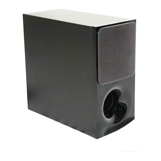
Photo: SA-WCT290 (Black) Photo: SA-WCT290 (White) /
Wireless transmitter/
receiver section
Frequency band
2.4 GHz (2.4000 GHz – 2.4835 GHz)
Modulation method
FHSS (Freq Hopping Spread Spectrum)
Design and specifications are subject to change without
notice.
Copyrights and Trademarks
•
This system incorporates Dolby* Digital.
* Manufactured under license from Dolby Laboratories.
Dolby, Dolby Audio, and the double-D symbol are
trademarks of Dolby Laboratories.
®
• The BLUETOOTH
word mark and logos are registered
trademarks owned by Bluetooth SIG, Inc. and any use of
such marks by Sony Corporation is under license. Other
trademarks and trade names are those of their respective
owners.
•
This system incorporates High-Defi nition Multimedia Inter-
face (HDMI™) technology.
The terms HDMI and HDMI High-Defi nition Multimedia
Interface, and the HDMI Logo are trademarks or registered
trademarks of HDMI Licensing, LLC in the United States
and other countries.
•
"BRAVIA" is a trademark of Sony Corporation.
•
"PlayStation" is a registered trademark of Sony Computer
Entertainment Inc.
•
MPEG Layer-3 audio coding technology and patents
licensed from Fraunhofer IIS and Thomson.
•
Windows Media is either a registered trademark or trademark
of Microsoft Corporation in the United States and/or other
countries.
Canadian Model
Australian Model
SA-WCT291
•
This product is protected by certain intellectual property
rights of Microsoft Corporation. Use or distribution of such
technology outside of this product is prohibited without a
license from Microsoft or an authorized Microsoft subsidiary.
•
"ClearAudio+" is a trademark of Sony Corporation.
•
Other system and product names are generally trademarks or
registered trademarks of the manufacturers. ™ and ® marks
are not indicated in this document.
ACTIVE SUBWOOFER
US Model
E Model
SA-WCT290
AEP Model
UK Model
SA-WCT290/WCT291
Advertisement
Table of Contents

Related Manuals for Sony SA-WCT290


Summary of Contents for Sony SA-WCT290
- Page 1 SA-WCT290/WCT291 Photo: SA-WCT290 (Black) Photo: SA-WCT290 (White) / SA-WCT291 • SA-WCT290/WCT291 is the active subwoofer in HT-CT290/CT291. • All the units included in the HT-CT290/CT291 (SA-CT290/CT291, SA- WCT290/WCT291, remote control) are required to confi rm the opera- tion of SA-CT290/CT291. Check in advance that you have all the units.
-
Page 2: Table Of Contents
LES DIAGRAMMES SCHÉMATIQUES ET LA LISTE DES PIÈCES SONT CRITIQUES POUR LA SÉCURITÉ DE FONC- TIONNEMENT. NE REMPLACER CES COMPOSANTS QUE PAR DES PIÈCES SONY DONT LES NUMÉROS SONT DON- NÉS DANS CE MANUEL OU DANS LES SUPPLÉMENTS PUBLIÉS PAR SONY. -
Page 3: Servicing Notes
SWITCHING REGULATOR 3L411L board (US, CND) or SWITCHING Model Part No. REGULATOR 3L411W board (Except US, CND, E12) or SA-WCT290 (Black): US, CND 4-688-018-0[] SWITCHING REGULATOR 3L411W-1 board (E12) to the SUB SA-WCT290 (Black): AEP 4-688-018-1[] MAIN board is disconnected before discharging, completely fi... - Page 4 All the units included in the HT-CT290/HT-CT291 (SA-CT290/ press on the subwoofer to turn CT291, SA-WCT290/WCT291, remote control) are required to off the power and check whether confi rm the operation of SA-CT290/CT291. Check in advance that the ventilation opening of the subwoofer is blocked or not.
- Page 5 SA-WCT290/WCT291 2. SWITCHING REGULATOR 3L411W board (Except US, CND, E12) – SWITCHING REGULATOR 3L411W board (Except US, CND, E12) (Component Side) – *The portion which applies bond: 3. SWITCHING REGULATOR 3L411W-1 board (E12) – SWITCHING REGULATOR 3L411W-1 board (E12) (Component Side) –...
-
Page 6: Disassembly
SA-WCT290/WCT291 SECTION 2 DISASSEMBLY • This set can be disassembled in the order shown below. 2-1. DISASSEMBLY FLOW 2-2. SUB MAIN SECTION 2-6. SUB LED BOARD, FRONT PANEL ASSY (Page 6) (Page 9) 2-7. LOUDSPEAKER (130mm)-203-11 2-3. SUB MAIN BOARD... - Page 7 SA-WCT290/WCT291 2-3. SUB MAIN BOARD Note 1: When the complete SUB MAIN board is replaced, refer to “NOTES ON THE WIRELESS CONNECTION (LINK) AFTER REPAIRS ARE COMPLETE” on page 4. SUB KEY board wire (flat type) (9 core) SWITCHING REGULATOR...
- Page 8 SA-WCT290/WCT291 2-4. SWITCHING REGULATOR 2 one screw 3 stopper, (+BVTP 3 wiring 1 CN1 (2P) 2 one screw 2 three screws (+BVTP 3 (+BVTP 3 4 SWITCHING REGULATOR 3L411W (EXCEPT US, CND, E12) SWITCHING REGULATOR 3L411W-1 (E12) SWITCHING REGULATOR 3L411L (US, CND) •...
- Page 9 SA-WCT290/WCT291 2-6. SUB LED BOARD, FRONT PANEL ASSY 1 Insert a jig in two notches of bottom of the unit, and lift the front panel section a little. 2 Insert the jig into a space and raise front panel section.
-
Page 10: Loudspeaker (130Mm)-203-11
SA-WCT290/WCT291 2-7. LOUDSPEAKER (130mm)-203-11 (130mm)-203-11 1 four screws Note: When installing the loudspeaker (1) (3.5 16), TAPPING (130mm)-203-11, make sure that there is a position of the speaker terminal to the position shown in the figure below. 4 loudspeaker (130mm)-203-11... -
Page 11: Troubleshooting
SA-WCT290/WCT291 SECTION 3 TROUBLESHOOTING... - Page 12 SA-WCT290/WCT291...
-
Page 13: Diagrams
SA-WCT290/WCT291 SECTION 4 DIAGRAMS 4-1. BLOCK DIAGRAM - AMP/PANEL/POWER SUPPLY Section - X001 STREAM PROCESSOR DIGITAL POWER AMP 12.288MHz IC8103 IC8104 L8102 MCLK PWM_P_4 INPUT_A OUT_A BLUETOOTH PWM_M_4 INPUT_B SUBWOOFER MODULE VALID RESET OUT_A I2S_SDO SDIN4 L8103 I2S_SCLK SCLK OUT_B... - Page 14 SA-WCT290/WCT291 THIS NOTE IS COMMON FOR PRINTED WIRING BOARDS AND SCHEMATIC DIAGRAMS. (In addition to this, the necessary note is printed in each block.) For Printed Wiring Boards. For Schematic Diagrams. Note: Note: • X : Parts extracted from the component side.
-
Page 15: Sub Main Board (Component Side)
SA-WCT290/WCT291 4-2. PRINTED WIRING BOARD - SUB MAIN Board (Component Side) - • : Uses unleaded solder. SUB MAIN BOARD (COMPONENT SIDE) SUB KEY BOARD CONNECT TO SWITCHING REGULATOR 3L411W CN8200 (EXCEPT US, CND, E12) (Page 17) SWITCHING REGULATOR 3L411W-1... -
Page 16: Sub Main Board (Conductor Side)
SA-WCT290/WCT291 4-3. PRINTED WIRING BOARD - SUB MAIN Board (Conductor Side) - • : Uses unleaded solder. SUB MAIN BOARD (CONDUCTOR SIDE) CL8133 CL8150 CL8128 CL8145 CL8176 CL8144 CL8169 CL8168 CL8156 CL8143 CL8178 CL8113 CL8157 CL8151 CL8172 CL8125 CL8175 CL8171... -
Page 17: Printed Wiring Board - Sub Key Board
SA-WCT290/WCT291 4-5. SCHEMATIC DIAGRAM - SUB KEY Board - 4-4. PRINTED WIRING BOARD - SUB KEY Board - • : Uses unleaded solder. SUB KEY BOARD (COMPONENT SIDE) SUB KEY BOARD CN8201 SUB MAIN BOARD CN8101 3.3V D_GND (Page 15) UART_RX >001P... -
Page 18: Printed Wiring Board - Sub Led Board
SA-WCT290/WCT291 4-7. SCHEMATIC DIAGRAM - SUB LED Board - 4-6. PRINTED WIRING BOARD - SUB LED Board - • : Uses unleaded solder. SUB LED BOARD (COMPONENT SIDE) SUB LED BOARD CN8300 R8300 CL8300 LED(G) SUB MAIN BOARD CL8301 LED(R) -
Page 19: Exploded Views
SA-WCT290/WCT291 SECTION 5 EXPLODED VIEWS Note: • -XX and -X mean standardized parts, so • Abbreviation The components identifi ed by mark 0 they may have some difference from the : Australian model or dotted line with mark 0 are critical for original one. -
Page 20: Sub Main Section
SA-WCT290/WCT291 5-2. SUB MAIN SECTION SUB KEY board (ns) Note 1: When the complete SUB MAIN board is replaced, refer to Note 3: When the BLUETOOTH module is replaced, refer to “NOTE OF REPLACING THE IC8104 ON THE SUB MAIN “NOTES ON THE WIRELESS CONNECTION (LINK) -
Page 21: Speaker Cabinet Section
SA-WCT290/WCT291 5-3. SPEAKER CABINET SECTION Ref. No. Part No. Description Remark Ref. No. Part No. Description Remark X-2594-348-1 PANEL, FRONT ASSY (CG-SW) B 1-859-203-11 LOUDSPEAKER (130MM)-203-11 (for Black model) (WCT290) 7-685-646-71 SCREW +BVTP 3X8 TYPE2 IT-3 X-2594-262-1 PANEL, FRONT ASSY (CG-SW) W... -
Page 22: Electrical Parts List
SA-WCT290/WCT291 SECTION 6 SUB KEY SUB LED ELECTRICAL PARTS LIST SUB MAIN Note: • Due to standardization, replacements in • COILS When indicating parts by reference num- the parts list may be different from the uH: μH ber, please include the board name. - Page 23 SA-WCT290/WCT291 MEMO...
- Page 24 SA-WCT290/WCT291 REVISION HISTORY Ver. Date Description of Revision 2017.02 How to search for a contact point of signal lines or the like in DIAGRAMS SECTION If a contact point of a BLOCK DIAGRAM, PRINTED WIRING BOARD or SCHEMATIC DIAGRAM is shown in a different page, use the PDF fi...