Table of Contents
Advertisement
& K D S W H U
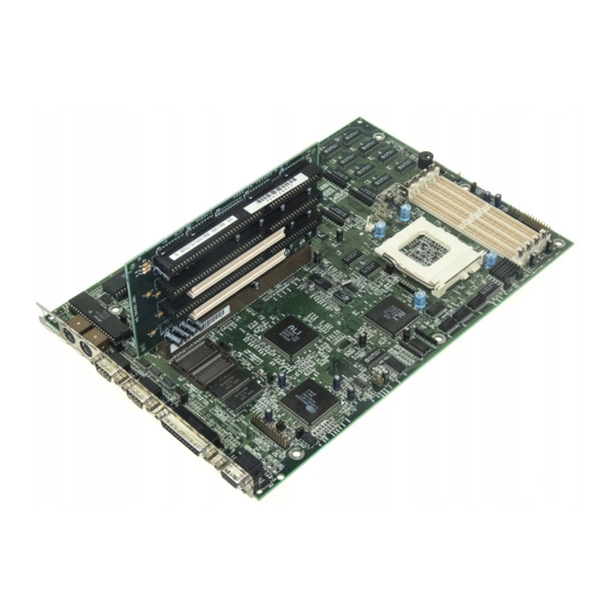
System Board
The V12LC is a high-performance Pentium PCI-based system board
that supports the 64-bit Pentium
microprocessor running at
75/90/100/120/133/150 MHz and has a 16-KB internal write-back
cache. It utilizes the Peripheral Component Interconnect (PCI) local
bus architecture.
The PCI local bus maximizes the system
performance by enabling high-speed peripherals to match the speed
of the microprocessor with its 120 MB or 132 MB per second transfer
rate in burst mode.
The system board features a slot for the PCI/ISA slot board and two
PCI enhanced IDE interfaces with a zero-wait state 11 MB per second
transfer rate and support up to four IDE devices. It has buffered serial
ports that reduce the number of interrupts to avoid slowing other
system activities. With the optional ECP/EPP function, the parallel
port transfers data at a fast 2 MB to 10 MB.
The system board has two DRAM banks composed of four 72-pin
sockets that support both single- and double-density SIMMs for a
maximum memory of 128 MB.
System Board
1-1
Advertisement
Table of Contents

Related Manuals for Acer V12LC


Summary of Contents for Acer V12LC
-
Page 1: System Board
& K D S W H U System Board The V12LC is a high-performance Pentium PCI-based system board that supports the 64-bit Pentium microprocessor running at 75/90/100/120/133/150 MHz and has a 16-KB internal write-back cache. It utilizes the Peripheral Component Interconnect (PCI) local bus architecture. -
Page 2: Major Features
Major Features The system board has the following major features: Pentium 75/90/100/120/133/150 MHz CPU in a zero-insertion force (ZIF) socket Two DRAM banks composed of four 72-pin SIMM sockets that support 4/8/16/32-MB 60/70ns SIMMs 16-KB internal cache and 256-KB write-back second-level cache 128-KB Flash ROM for system and VGA BIOS Two PCI enhanced IDE interfaces that support up to four IDE devices... - Page 3 1.1.1 Layout Figure 1-1 shows the locations of the system board major components. Keyboard controller Feature socket for multimedia or Ethernet solution (optional) Flash memory BIOS Real-time clock Slot board connector Voltage regulator Second-level cache SIMM sockets 320-pin ZIF CPU socket Figure 1-1 System Board Layout System Board...
- Page 4 1.1.2 Slot Board The system board comes with a slot board already installed. The slot board carries the PCI and ISA bus slots for system enhancements and future expansion. The slot board may vary in size and layout depending on your system housing.
- Page 5 Figure 1-4 3-PCI/5-ISA Slot Board (for generic mini-tower systems) Figure 1-5 3-PCI/4-ISA Slot Board (for Aspire mini-tower systems) System Board...
-
Page 6: Jumper And Connector Locations
Jumpers and Connectors 1.2.1 Jumper and Connector Locations Figure 1-6 shows the jumper and connector locations on the system board. Figure 1-6 System Board Jumper and Connector Locations Jumpers are prefixed “JP”. Connectors are prefixed “CN”. The blackened pin of a jumper represents pin 1. -
Page 7: Jumper Settings
When your Flash ROM is Intel 28F001 (JP3 is set to pins 2-3), refer to JP20 for the Flash ROM control settings. Default setting System Board Function For models with Acer BIOS For models with OEM BIOS Check password Bypass password For 29EE010 only EPROM... - Page 8 Table 1-1 System Board Jumper Settings (continued) Jumper Setting CPU Voltage JP13 CPU Core / Local Bus Clock Ratio JP14, JP18 , 1-2 2-3, 1-2 1-2, 2-3 2-3, 2-3 Reset Switch JP15 CN1 Connector Type JP16, JP17 HDD/FDD LED Control JP19 Open Closed...
-
Page 9: Connector Functions
1.2.3 Connector Functions Table 1-2 lists the different connectors on the system board and their respective functions. Table 1-2 Connector Functions Connector VGA feature connector PCI IDE channel 1 PCI IDE channel 2 Diskette drive connector Power connector Multifunction connector Multifunction connector Hard disk LED connector Reserved... -
Page 10: Esd Precautions
Figure 1-8 8-pin Multifunction Connector (CN7) ESD Precautions Always observe following precautions before installing a system component: Do not remove a component from its antistatic packaging until you are ready to install it. Wear a wrist grounding strap before handling electronic components. -
Page 11: Memory Upgrade
Memory Upgrade The system board comes with four 72-pin SIMM sockets that support 4-MB and 16-MB single-density SIMMs and 8-MB and 32-MB double- density SIMMs. Table 1-3 lists the possible memory configurations. Table 1-3 Memory Configurations Bank 0 SIMM-1 SIMM-2 SIMM-3 4 MB 4 MB... -
Page 12: Installing A Simm
1.4.1 Installing a SIMM Follow these steps to install a SIMM: Slip a SIMM at a 45 angle with the component side facing down into the socket labeled SIMM-1. Be careful when inserting SIMMs to avoid damaging the SIMM or the socket. Gently press the SIMM up until the pegs of the socket fit into the holes on the SIMM and the holding clips lock the SIMM into position. -
Page 13: Removing A Simm
1.4.2 Removing a SIMM Follow these steps to remove a SIMM: Press the holding clips on both sides of the SIMM outward to release it. Figure 1-10 Removing a SIMM Move the SIMM to a 45 angle. Pull the SIMM out of the socket. Always remove SIMMs from the socket labeled SIMM-4, then SIMM-3, and so on. -
Page 14: Reconfiguring The System
1.4.3 Reconfiguring the System You must enter Setup after installing or removing SIMMs to reconfigure the system. Follow these steps to reconfigure the system: Turn the system on. A memory error message appears, indicating that the total memory does not match the value stored in CMOS. -
Page 15: Cpu Installation
CPU Installation The system board comes with a zero-insertion force (ZIF) CPU socket for easy installation. Follow these steps to install a Pentium CPU: Lift up the socket lever. Insert the CPU to the socket. Make sure that the notched corner of the CPU matches the pin 1 indicator on the socket. -
Page 16: Video Memory Upgrade
Video Memory Upgrade Larger video memory allows you to display higher resolutions and more colors. The system board comes with a 1-MB video memory onboard upgradable to 2 MB. Follow these steps to upgrade the video memory: Locate the video DRAM upgrade sockets labeled U12 and U13 on the system board. -
Page 17: Software Error Messages
Error Messages Do not continue using the computer if you receive an error message of any type. Note the message and take corrective action. This section explains the different types of error messages and corresponding corrective measures. There are two general types of error messages: Software System 1.8.1... - Page 18 Table 1-5 System Error Messages Message CMOS Battery Error CMOS Checksum Error Display Card Mismatch Diskette Drive Controller Error or Not Installed Diskette Drive Error Diskette Drive A Type Mismatch Diskette Drive B Type Mismatch Equipment Configuration Error Fixed Disk Controller Error Fixed Disk 0 Error Fixed Disk 1 Error Keyboard Error or No...
- Page 19 Table 1-5 System Error Messages (continued) Message Memory Error at: MMMM:SSSS:OOO (W:XXXX, R:YYYY) where: M: MB, S: Segment, O: Offset, X/Y: write/read pattern Memory Size Mismatch CPU Clock Mismatch Onboard Serial Port 1 Conflict Onboard Serial Port 2 Conflict Onboard Parallel Port Conflict Pointing Device Error Pointing Device Interface Error...
-
Page 20: Correcting Error Conditions
1.8.3 Correcting Error Conditions As a general rule, if an error message says "Press F1 to continue," it is caused by a configuration problem, which can be easily corrected. An equipment malfunction is more likely to cause a fatal error, i.e., an error that causes complete system failure.