Table of Contents
Advertisement
Advertisement
Table of Contents

Related Manuals for Sony HDVF-L750


Summary of Contents for Sony HDVF-L750
- Page 1 LCD COLOR VIEWFINDER HDVF-L750 HDVF-L770 SERVICE MANUAL 1st Edition...
- Page 2 à moins d’être qualifié pour en effectuer d’autres. Pour toute réparation faire appel à une personne compétente uniquement. Model Name Serial No. HDVF-L750 (SY) 0100001 and Higher HDVF-L750 (CN) 0500001 and Higher HDVF-L770 (SY)
-
Page 3: Table Of Contents
VF Holder Assembly (HDVF-L770)/Rear Panel Assembly (HDVF-L750)........ - Page 4 Frame Wiring......................... . .7-3 HDVF-L750/HDVF-L770...
-
Page 5: Manual Structure
• Factory Service Manual (Available on request) This manual describes the information items that premise the service based on the components parts. Trademarks System names and product names written in this manual are usually registered trademarks or trademarks of respective development manufacturers. HDVF-L750/HDVF-L770... -
Page 7: Service Overview
Section 1 Service Overview 1-1. Board Location HDVF-L770 PR-332 SW-1637 SW-1638 CN-3713 SW-1636 CN-3715 VR-352 HDVF-L750 PR-332 CN-3713 SW-1636 CN-3715 VR-352 HDVF-L750/HDVF-L770... -
Page 8: Connectors And Cables
0.7 Vp–p, Zi=75 Ω 1-2-1. Connection Cables REC (L) ON: +5 V OFF: GND When connecting the HDVF-L750/L770 to a camera at the time R TALLY ON: +5 V OFF: GND of installation or service, use the supplied connection cable. —... - Page 9 0.8 Vp-p, 75 Ω, 1.485 Gbps/1.4835 Gbps 4. DC IN DIN, 4-pin, Male - External View - Signal Specifications UNREG GND — GND for UNREG TALLY ON: GND OFF: High impedance (Open collector) — No connection UNREG +10.5 to 17 V dc, 2 A (max) HDVF-L750/HDVF-L770...
-
Page 10: Onboard Switches
6 to 8 Not used All OFF All these bits were set to off when the board was purchased. When installing this board to the HDVF-L750/L770, change the setting of these bits in accordance with the model and destination. HDVF-L750/HDVF-L770... -
Page 11: Pr-332 Board
1-4. Circuit Description HDVF-L750/HDVF-L770 consists of the following boards. • PR-332 board • CN-3713 board • CN-3715 board • SW-1636 board • SW-1637/SW-1638 boards (HDVF-L770 only) • VR-352 board 1-4-1. PR-332 Board The PR-332 board mainly consists of a power supply block, a video input block, a video signal processing circuit, a tally control circuit, and a microcomputer. - Page 12 POWERGOOD pin is turned low. The POWERGOOD pin output signal is input to IC1003. When an error is detected, the SHUTDOWN signal is output. This SHUT DOWN signal turns off Q1605 to shut off the UNREG power supply. HDVF-L750/HDVF-L770...
-
Page 13: Cn-3713 Board
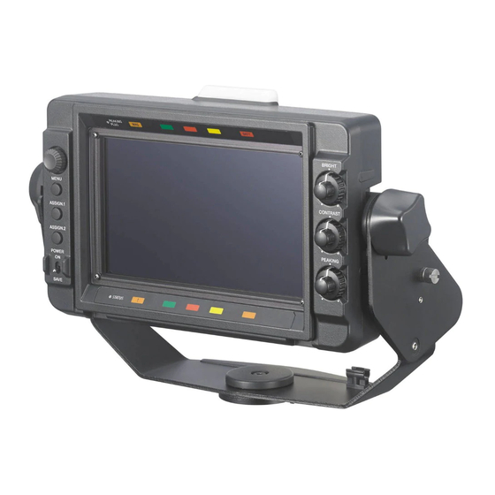
S303), and POWER ON/SAVE switch (S301). 1-4-5. SW-1637/SW-1638 Boards (HDVF-L770 only) Each of these boards contains two ASSINABLE switches (SW-1637: S400, S401 / SW-1638: S500, S501). 1-4-6. VR-352 Board This board contains three potentiometers BRIGHT (RV600), CONTRAST (RV601), and PEAKING (RV602). HDVF-L750/HDVF-L770... -
Page 14: Coaxial Cable
Firmly insert the connector straight as far as it will go. Insert the connector straight matching the polarity marks. 1-5-2. Disconnecting/Connecting Coaxial Cable Note Be sure to observe the disconnecting and connecting procedures below to prevent wire disconnection or poor contact. Required Tool • Connector remover (Part No: J-7121-210-A) HDVF-L750/HDVF-L770... - Page 15 • Do not attempt to pull the cable. Coaxial cable Notch Connector remover Connecting Hold the plug of the coaxial cable. Push the plug perpendicularly to the connector while slightly turning the plug clockwise and counterclockwise. Hold the plug to connect Connecting connector HDVF-L750/HDVF-L770...
-
Page 16: Service Tools/Equipment
Connector remover Disconnecting coaxial cables Commercially available Xilinx Platform Cable USB II Used for PLD data downloading 1-6-2. Equipment Equipment Model name HDD camera The camera indicated to the "Related Equipment" of the OPERATION MANUAL. General-purpose personal computer — 1-10 HDVF-L750/HDVF-L770... -
Page 17: Locations For Greasing
Knob (threads) Cone lock shoe (top surface) • Slide base Lift center shaft groove Lift center shaft grooves Lift center shaft grooves U grooves Warm gear shafts (upper/lower) Wheel gear hole inside (only both ends) Gear engaging portion 1-11 HDVF-L750/HDVF-L770... -
Page 18: Adjusting The Arm Lift Angle
• Set the arm angle to 5 degrees upward and contact the arm with the stopper pin as shown in the figure. • Apply locking compound to the two setscrews and tighten them to the specified torque. Lower-limit setting of lift stopper setscrews Lift stopper Stopper pin (Tightening torque: 0.8 ± 0.12 N•m) 1-12 HDVF-L750/HDVF-L770... - Page 19 • Apply locking compound to the two setscrews and tighten them to the specified torque. Lower-limit setting of lift stopper setscrews Lift stopper Stopper pin (Tightening torque: 0.8 ± 0.12 N•m) Install the removed parts by reversing the steps of removal. 1-13 HDVF-L750/HDVF-L770...
-
Page 20: Firmware And Pld Upgrading
Confirm the version of ROM and software. 1-9-2. Writing and Rewriting Software If software data needs to be upgraded, contact your local Sony Sales Office/Service Center. 1-9-3. Writing and Rewriting PLD Internal Data If PLD needs to be upgraded, contact your local Sony Sales Office/Service Center. -
Page 21: Notes On Replacing The Board
Mount IC1208 removed in step 2 on the new PR-332 board. Install the PR-332 board to the unit. Connect the unit to the camera and turn on the power of the unit. Check that video image is displayed. 1-15 HDVF-L750/HDVF-L770... -
Page 22: Lead-Free Solder
• The ordinary soldering iron can be used but the iron tip has to be applied to the solder joint for a slightly longer time. The printed pattern (copper foil) may peel away if the heated tip is applied for too long, so be careful. 1-16 HDVF-L750/HDVF-L770... -
Page 23: Replacement Of Main Parts
• Since small screws are used in the unit, they may fall into the unit when they are removed and installed. To prevent screws from falling, it is recommended that the bit of each torque driver be magnetized to a degree that prevents screws from falling. HDVF-L750/HDVF-L770... -
Page 24: Vf Holder Assembly (Hdvf-L770)/Rear Panel Assembly (Hdvf-L750)
Knob (ARM SIDE) Knob (ARM SIDE) Open the CN cap in the direction of the arrow. Remove the six screws to detach the VF holder assembly (HDVF-L770) /rear panel assembly (HDVF-L750). B3 x 6 B3 x 6 B3 x 6... -
Page 25: Cn Assembly
Illustration: HDVF-L770 Preparation Remove the VF holder assembly. (Refer to “2-2. VF Holder Assembly (HDVF-L770)/Rear Panel Assembly (HDVF-L750)”) Procedure Disconnect the coaxial cable from the connector (CN501) on the PR-332 board. Open the harness protection sheet. Disconnect the three harnesses from the three connectors (CN100, CN1900, and CN1901) on the PR-332 board. -
Page 26: Pr-332 Board
2-4. PR-332 Board Illustration: HDVF-L770 Preparation Remove the VF holder assembly. (Refer to “2-2. VF Holder Assembly (HDVF-L770)/Rear Panel Assembly (HDVF-L750)”) Remove the CN assembly. (Refer to “2-3. CN Assembly”) Procedure Remove the tape A. Disconnect the two harnesses from the two connectors (CN1500, CN1501) on the PR-332 board. - Page 27 Remove the four radiation sheets, drop protection, and the switch knob from the PR-332 board. Radiation rubber Drop protection PR-332 board Switch knob Screws VF GND plate Connector plate Install the removed parts by reversing the steps of removal. HDVF-L750/HDVF-L770...
-
Page 28: Lcd Module
2-5. LCD Module Illustration: HDVF-L770 Preparation Remove the VF holder assembly. (Refer to “2-2. VF Holder Assembly (HDVF-L770)/Rear Panel Assembly (HDVF-L750)”) Remove the CN assembly. (Refer to “2-3. CN Assembly”) Remove the PR-332 board. (Refer to “2-4. PR-332 Board”) Procedure Remove the two tapes A. - Page 29 Peal the two noise suppression sheets (1). Fine-wire coaxial cable LCD module Connector Noise suppression sheet (1) Remove the two noise suppression sheets (1). Noise suppression sheets (1) LCD module HDVF-L750/HDVF-L770...
- Page 30 • When attaching the noise suppression sheets (1), do not ride it on the step. • Be careful because the noise suppression sheets (1) are easily damaged by tugging. Note for installing Step Step LCD module Noise suppression sheet (1) Noise suppression sheets (1) HDVF-L750/HDVF-L770...
-
Page 31: Sw-1636 Board
2-6. SW-1636 Board Illustration: HDVF-L770 Preparation Remove the VF holder assembly. (Refer to “2-2. VF Holder Assembly (HDVF-L770)/Rear Panel Assembly (HDVF-L750)”) Remove the CN assembly. (Refer to “2-3. CN Assembly”) Remove the PR-332 board. (Refer to “2-4. PR-332 Board”) Procedure Remove the RE knob. - Page 32 Remove the drop protection rubber and the cushion. Tape A (HDVF-L770 only) Harness (HDVF-L770 only) Harness PSW3 x 8 SW harness protection sheet Cushion SW-1636 board CN300 Drop protection rubber CN302 Install the removed parts by reversing the steps of removal. 2-10 HDVF-L750/HDVF-L770...
-
Page 33: Vr-352 Board
2-7. VR-352 Board Illustration: HDVF-L770 Preparation Remove the VF holder assembly. (Refer to “2-2. VF Holder Assembly (HDVF-L770)/Rear Panel Assembly (HDVF-L750)”) Remove the CN assembly. (Refer to “2-3. CN Assembly”) Remove the PR-332 board. (Refer to “2-4. PR-332 Board”) Procedure Remove the three volume knobs. -
Page 34: Sw-1637 Board (Hdvf-L770)
Hexagon socket bolt Handle cover (right) CN400 SW-1637 board Harness B2 x 6 Handle base Note When installing, do not have a gap between SW-1637 board and handle base. Install the removed parts by reversing the steps of removal. 2-12 HDVF-L750/HDVF-L770... -
Page 35: Sw-1638 Board (Hdvf-L770)
Hexagon socket bolt Handle cover (left) Harness CN500 B2 x 6 SW-1638 board Handle base Note When installing, do not have a gap between SW-1638 board and handle base. Install the removed parts by reversing the steps of removal. 2-13 HDVF-L750/HDVF-L770... -
Page 36: Arm (R) Sub Assembly (Hdvf-L770)
Remove the two screws (B3 x 5) to detach the lift base cover (R). Remove the lift arm cover. Tilt base cover K3 x 6 Lift base cover (R) Lift arm cover B3 x 5 Remove the three screws (B3 x 5) to lift lock shoe. 2-14 HDVF-L750/HDVF-L770... - Page 37 Loose the three set screws. Set screw Set screws Lift lock shoe B3 x 5 Remove the two screws (K3 x 6) and the four screws (B3 x 5) to detach the arm (R) sub assembly. Arm (R) sub assembly K3 x 6 B3 x 5 2-15 HDVF-L750/HDVF-L770...
- Page 38 Install the removed parts by reversing the steps of removal. Note When installing, tighten the three set screws after right and left of portions A and B are grounded. Set screw Set screw Set screw Portion A Portion B 2-16 HDVF-L750/HDVF-L770...
-
Page 39: Arm (L) Sub Assembly (Hdvf-L770)
Remove the stopper knob screw to detach the two springs, friction plate, and the friction sheet. Orientation for install Friction sheet Friction plate Springs Springs Knob (ARM SIDE) Stopper knob screw Note When installing the springs, pay attention to the orientation of the springs. 2-17 HDVF-L750/HDVF-L770... - Page 40 When installing the springs, pay attention to the orientation of the springs. Following disassembly is the same as arm (R) sub assembly. refer to the “2-10. Arm (R) Sub Assembly (HDVF- L770)”. Install the removed parts by reversing the steps of removal. 2-18 HDVF-L750/HDVF-L770...
-
Page 41: Pan Tilt Base Assembly (Hdvf-750)
Pan Tilt Base Assembly (HDVF-750) Procedure Remove the four hexagon socket bolts to detach the pan tilt base assembly. Hexagon socket bolts Hexagon socket bolts Pan tilt base assembly Install the removed parts by reversing the steps of removal. 2-19 HDVF-L750/HDVF-L770... -
Page 43: Diagnostics
Check the contents of a failure in “S08 DIAGNOSIS” of a seconds. self-diagnosis. SERVICE menu. (Refer to “4-2-3. SERVICE Menu”) The error messages below may be displayed. BACKUP ERROR: The backup data of EEPROM does not co- incide in checksum. DEVICE ERROR: Device errors other than those described above HDVF-L750/HDVF-L770... -
Page 44: Device Check
Device Check This unit has a self-diagnosis function that checks the communication function of each device. The result of diagnosis is displayed in “S08 DIAGNOSIS” of a SERVICE menu. (For more details, refer to “4. Setup Menu” “4-2-3. SERVICE Menu”) HDVF-L750/HDVF-L770... -
Page 45: Internal Test Signal
——— (No output) TEST POINT Switch the S1202 (bits 3,4 and 5) to change the point ( [1] to [7] ) of the signal to output to the test pin (TP700) . Check point S1202 setting bit3 bit4 bit5 Continued HDVF-L750/HDVF-L770... - Page 46 Check point S1202 setting bit3 bit4 bit5 ——— ( [7] ) HDVF-L750/HDVF-L770...
-
Page 47: Setup Menu
The OPERATION menu is displayed when you press the MENU switch. 2. Select the menu page. Turn the MENU control with the “?” mark displayed before the page number (in the page selection mode), display the desired page, and press the MENU control. HDVF-L750/HDVF-L770... - Page 48 Press the MENU control for two seconds or more with the “?” mark displayed in the setting value to be returned to the factory setting (in the setting value change mode). The operation above is applied to only the operation from a TOP menu. Refer to “4-2-1. TOP Menu” HDVF-L750/HDVF-L770...
-
Page 49: Description Of Menu
Note • The item may be not able to be selected in the menu item below by the current menu item setting. • For the item that cannot be selected, “— — —” is displayed in the setting value. HDVF-L750/HDVF-L770... - Page 50 0 to [xx] to 255 Adjusts the luminance level. Continued Refer to AUTO RELEASE of OPERATION MENU 03 MAGNIFICATION. Check whether the camera to be connected supports VF ASSIGNABLE SW. Necessarily operates in the OFF state when the power is turned on. HDVF-L750/HDVF-L770...
- Page 51 The current display is shifted to the execution screen below by moving a “→” mark to EXEC and pressing the MENU control. Place the detection area marker at the color you want to correct. This function is executed by moving the “→” mark to “YES” and pressing the MENU control. VF MENU Detection area marker EXEC HDVF-L750/HDVF-L770...
- Page 52 The current display is shifted to the execution screen below by moving a “→” mark to EXEC and pressing the MENU control. Place the detection area marker at the color you want to correct. This function is executed by moving the “→” mark to “YES” and pressing the MENU control. VF MENU S11 RESET EXEC MENU RESET EXEC HDVF-L750/HDVF-L770...
- Page 53 VF MENU S11 RESET EXEC MENU RESET EXEC The items on page S03 in the SERVICE menu is adjusted during factory setting. They are not reset even if MENU RESET is executed. For the adjustment, refer to “5. Electrical Adjustment” HDVF-L750/HDVF-L770...
-
Page 55: Electrical Adjustment
Enter the set values written on the adjustment data label in all items of the “S03: C. TEMP/BACKLIGHT” menu. Check that the set values entered in step 4 is the same as the set values written on the adjustment data label. Turn off and on the power and check that a video image is displayed. HDVF-L750/HDVF-L770... -
Page 57: Spare Parts
Therefore, specified parts should be used in the case 指定の部品を使ってください。 of replacement. 2. Standardization of Parts 2. 部品の共通化 Some repair parts supplied by Sony differ from those ソニーから供給する補修用部品は,セットに使われ used for the unit. These are because of parts common- ているものと異なることがあります。 ality and improvement. -
Page 58: Exploded Views
1-970-463-11 s HARNESS, COAXIAL (130MM) 3-669-607-91 s +PSW (SMALL ROUND) (2.6) [PSW 2.6X6] 7-682-547-09 s SCREW +B 3X6 3-796-995-01 s DROP PROTECTION(SW) 3-965-077-02 s SCREW, SPECIAL (M2) 4-382-854-01 s SCREW (M3X8), P, SW (+) HDVF-L750/HDVF-L770... - Page 59 3-080-272-01 s TAPE (A) 3-869-883-01 s RUBER, DROP PROTECTION 4-183-519-01 s KNOB(B), RE (HDVF-L770) 3-692-111-02 s KNOB, RE (HDVF-L750) 4-195-859-04 s KNOB, VOLUME 4-382-854-01 s SCREW (M3X8), P, SW (+) 4-542-838-01 s CUSHION, LCD ...
- Page 60 4-542-844-01 s SHEET (LOWER), DROP PROTECTION 3-676-244-03 s COVER, SWITCH 4-542-949-01 s PANEL, FRONT (HDVF-L770) 4-542-949-11 s PANEL, FRONT (HDVF-L750) 3-685-694-02 s NYLOCK +PSW M4 [PSW 4X12] 4-542-951-01 s PLATE, LCD PROTECTION 3-729-076-21 s SCREW (+B) (2X6) ...
- Page 61 Base Pan Tilt Assembly (HDVF-L750) HEXAGON BOLT 3 x 8 HEXAGON BOLT 8 x 12 B2.6 x 5 HEXAGON BOLT 3 x 8 HEXAGON BOLT 5 x 10 HEXAGON BOLT 8 x 12 BTP2.6 x 8 SET2.6 x 3 SET2.6 x 3 P4 x 6 Part No.
- Page 62 4-195-519-01 s BASE GUARD (P) 4-195-522-01 s BASE (TOP), PAN 4-195-523-02 s BASE (BOTTOM), PAN 4-195-525-02 s SHEET, PAN 7-682-546-09 s SCREW +B 3X5 7-682-561-04 s SCREW +B 4X8 7-683-435-04 s BOLT, HEXAGON SOCKET 5X10 HDVF-L750/HDVF-L770...
- Page 63 4-195-452-01 s NAME PLATE (+- ARROW) 4-195-869-11 s ADHESIVE(TALLY) 4-195-870-02 s COVER, TALLY 4-542-847-01 s SHEET (4), DROP PROTECTION 4-542-878-01 s HOLDER, CABLE 4-174-649-11 s SEAL,TALLY COVER 4-547-669-01 s GASKET, CN 7-621-775-20 s SCREW +B 2.6X5 HDVF-L750/HDVF-L770...
- Page 64 4-195-421-01 s NAME PLATE (TILT LOCK) 4-195-444-03 s KNOB (ARM SIDE) 4-195-445-01 s STOPPER KNOB SCREW 3-701-506-01 s SET SCREW, DOUBLE POINT 3X4 7-682-247-09 s SCREW +K 3X6 7-682-545-09 s SCREW +B 3X4 7-682-546-09 s SCREW +B 3X5 HDVF-L750/HDVF-L770...
- Page 65 4-195-450-02 s LIFT BASE COVER (L) 4-195-451-02 s LIFT ARM COVER (L) 4-542-880-01 s COVER, CN 4-542-950-01 s PANEL, REAR 7-682-247-09 s SCREW +K 3X6 7-682-545-09 s SCREW +B 3X4 7-682-546-09 s SCREW +B 3X5 HDVF-L750/HDVF-L770...
-
Page 66: Supplied Accessories
6-3. Supplied Accessories HDVF-L750 Q'ty Part No. SP Description A-2057-914-A s HOOD (750) ASSY, INDOOR A-7612-405-F s SHOE ASSY, V EDGE 1-838-608-21 s CORD, CONNECTION (VF) 20P 1-848-062-21 s CABLE, CONNECTION (VF) 26P 4-027-937-03 s PLATE, NUMBER 4-542-851-01 s BRACKET, SHOE CONVERSION... -
Page 67: Diagrams
11,12 11,12 ASSIGNABLE6 IC1501 EN300 RE_A/B RE_A/B RE_A/B 16MHz RE_SW RE_SW MENU S1201 S300 MENU_SW MENU_SW INPUT S301 IC1500 POWER_SAVE POWER_SAVE POWER_OFF POWER ON/SAVE POWER_OFF_CTL CN100 VR-352 BRIGHT, BRIGHT, CONTRAST, CONTRAST, CN1501 CN600 RV600-602 RV600:BRIGHT PEAKING PEAKING RV601:CONTRAST RV602:PEAKING HDVF-L750/HDVF-L770... - Page 68 +1.2V_S UNREG_26P CN101 IC1705 Q1638 +1.0V_S Q1642 Q1633 POWER_SENSE_26P IC1701 L1704,C1718 +3.3V +1.2V DC/DC Q1602 CONV IC1702 L1705,C1719 +3.3V +1.0V_FPGA DC/DC CONV IC1800 L1801,C1803 +5V_A DC/DC CONV IC1803 L1805,C1812,1813 -5V_A DC/DC CONV IC1801 L1803,C1806 DC/DC +3.3V_A CONV IC1802 +1.8V_A HDVF-L750/HDVF-L770...
-
Page 69: Frame Wiring
HARNESS FRONT PANEL D1533-1548 (SW1) (LEFT) S302 REAR PANEL TALLY ASSIGNABLE5 S303 ASSIGNABLE6 S301 POWER ON/SAVE HARNESS (SW2) SW-1637 S400 ASSIGNABLE3 HANDLE S401 (RIGHT) ASSIGNABLE4 HDVF-L770 ONLY VR-352 RV600 BRIGHT HARNESS (VR) RV601 FRONT PANEL CONTRAST (RIGHT) RV602 PEAKING HDVF-L750/HDVF-L770... - Page 72 HDVF-L750 (SY) HDVF-L750 (CN) HDVF-L770 (SY) Printed in Japan Sony Corporation HDVF-L770 (CN) J, E 2014. 7 08 9-878-584-01 © 2014...