
Related Manuals for Toro ProCore SR Series


Summary of Contents for Toro ProCore SR Series
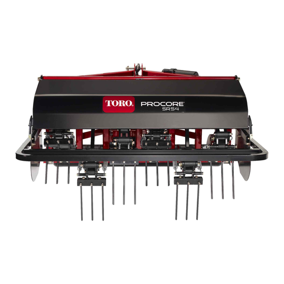
- Page 1 Form No. 10174SL Rev A ® ProCore SR Series (Models SR48, SR54, SR54-S, SR70, SR70-S, SR72 and SR75) Original Instructions (EN)
- Page 2 THE TORO COMPANY 2018 This document and all information contained herein is the sole property of The Toro Company (and/or its affiliated companies). No intellectual property rights are granted by the delivery of this document or the disclosure of its content. This document shall not be...
- Page 3 Reader Comments The Toro Company Technical Assistance Center maintains a continuous effort to improve the quality and usefulness of its publications. To do this effectively, we encourage user feedback. Please comment on the completeness, accuracy, organization, usability, and readability of this manual by an e-mail to servicemanuals@toro.com...
- Page 4 NOTES...
- Page 5 The purpose of this publication is to provide the service technician with information for troubleshooting, testing and repair of major systems and components on the ProCore SR series deep tine aerators: models SR48, SR54, SR54--S, SR70, SR70--S, SR72 and SR75. This safety symbol means DANGER, WARNING, or CAUTION, PERSONAL SAFETY INSTRUC- REFER TO THE OPERATOR’S MANUAL FOR OPER-...
- Page 6 This page is intentionally blank. ProCore SR Series...
- Page 7 ......7 -- 1 Service and Repairs ......7 -- 2 ProCore SR Series...
- Page 8 This page is intentionally blank. ProCore SR Series...
-
Page 9: Table Of Contents
....SAFETY AND INSTRUCTION DECALS ..ProCore SR Series Page 1 - - 1 Safety... -
Page 10: Safety Instructions
Safety Instructions The ProCore SR series of deep tine aerators are de- signed and tested to offer safe service when operated WARNING and maintained properly. Although hazard control and accident prevention partially are dependent upon the design and configuration of the machine, these factors... -
Page 11: While Operating
Apply tractor park- performance and continued safety certification of the ing brake, stop engine and remove key from the ignition machine, use genuine Toro replacement parts and ac- switch. cessories. Replacement parts and accessories made 3. -
Page 12: Safety And Instruction Decals
Safety and Instruction Decals Numerous safety and instruction decals are affixed to the ProCore SR series deep tine aerator. If any decal becomes illegible or damaged, install a new decal. Part numbers for replacement decals are listed in your Parts Catalog. - Page 13 ......Product Records Insert Operator’s Manual and Parts Catalog for your ProCore SR Series deep tine aerator at the end of this chapter. Additionally, if any optional equipment or ac- cessories have been installed to your ProCore, insert the Installation Instructions, Operator’s Manuals and...
- Page 14 Equivalents and Conversions 0.09375 Product Records and Maintenance Page 2 - - 2 ProCore SR Series...
- Page 15 For critical applications, as determined reduced by 25% for lubricated fasteners to achieve by Toro, either the recommended torque or a torque that the similar stress as a dry fastener. Torque values may is unique to the application is clearly identified and spe- also have to be reduced when the fastener is threaded cified in this Service Manual.
- Page 16 The specific torque value should be determined based on the fastener size, the aluminum or base material strength, length of thread engagement, etc. Product Records and Maintenance Page 2 - - 4 ProCore SR Series...
- Page 17 The specific torque value should be determined based on the fastener size, the aluminum or base material strength, length of thread engagement, etc. ProCore SR Series Page 2 - - 5 Product Records and Maintenance...
- Page 18 -lb X 11.2985 = N- -cm N- -cm X 0.08851 = in- -lb ft- -lb X 1.3558 = N- -m N- -m X 0.7376 = ft- -lb Product Records and Maintenance Page 2 - - 6 ProCore SR Series...
- Page 19 Operator’s Manual The Operator’s Manual provides information regarding the operation, general maintenance and maintenance intervals for your ProCore aerator. Refer to this publica- tions for additional information when servicing the ma- chine. ProCore SR Series Page 3 - - 1 Chassis...
-
Page 20: Roller (Procore Sr54, Sr54--S, Sr70 And Sr70--S)
The ProCore SR54 is shown in Figure 1. 2. Support aerator to prevent it from moving. 3. Chock roller to prevent it from moving. Chassis Page 3 - - 2 ProCore SR Series... - Page 21 Figure 3 1. Bearing 3. Set screw (2 used) 2. Bearing housing (2 bolt) 4. Grease fitting ProCore SR Series Page 3 - - 3 Chassis...
-
Page 22: Roller (Procore Sr48 And Sr72)
Support raised aerator to prevent it from lowering unex- switch. pectedly. 2. Support aerator to prevent it from moving. 3. Chock roller to prevent it from moving. Chassis Page 3 - - 4 ProCore SR Series... - Page 23 Figure 5 1. Bearing 3. Set screw (2 used) 2. Bearing housing (4 bolt) 4. Grease fitting 3. Position roller with vertical roller bars and flange bea- rings under raised aerator. ProCore SR Series Page 3 - - 5 Chassis...
-
Page 24: Roller (Procore Sr75)
(Fig. 7). 5. Remove four (4) cap screws and lock nuts that se- 7. Remove roller with flange bearings from under ma- cure flange bearings (item 4) to aerator frame. chine. Chassis Page 3 - - 6 ProCore SR Series... - Page 25 6. Apply Loctite #242 (or equivalent) to threads of bear- ing set screws. Tighten two (2) set screws to secure each bearing locking collar to roller shaft. 7. Lubricate grease fittings on bearings. ProCore SR Series Page 3 - - 7 Chassis...
-
Page 26: Pto Driveshaft
2. Unhook driveshaft shield safety chains from the trac- C. Slide driveshaft coupler from gearbox shaft. tor and the aerator driveshaft shield. 6. Remove driveshaft from machine. 3. Support PTO driveshaft to prevent it from falling. Chassis Page 3 - - 8 ProCore SR Series... - Page 27 Note: PTO driveshaft shield is not shown in this illustration. Figure 10 1. Driveshaft coupler 3. Pin 2. Gearbox input shaft 4. Nut ProCore SR Series Page 3 - - 9 Chassis...
-
Page 28: Pto Driveshaft Clutch Service
ProCore SR models is similar. become hot during use. To prevent personal in- jury, make sure that clutch has cooled before performing any service on the driveshaft. Chassis Page 3 - - 10 ProCore SR Series... - Page 29 4. After installation is complete, check that clutch does not slip. If clutch is slipping, tighten nuts equally in 1/4 turn increments until clutch slippage ceases. Figure 13 1. Cap screw 3. Nut 2. Spring 4. Flange yoke ProCore SR Series Page 3 - - 11 Chassis...
-
Page 30: Pto Driveshaft Cross And Bearing Service
4. Shaft yoke B. Press one bearing partially into yoke. IMPORTANT: Take care when installing cross into bearing to avoid damaging bearing seal. C. Carefully insert cross into bearing and yoke. Chassis Page 3 - - 12 ProCore SR Series... - Page 31 This page is intentionally blank. ProCore SR Series Page 3 - - 13 Chassis...
-
Page 32: Hydraulic Top Link
2. Remove spacers (item 16) from cylinder shaft clevis plate to head. Position plate away from cylinder barrel and adapter on barrel end. to allow access to retaining ring (item 4). Chassis Page 3 - - 14 ProCore SR Series... - Page 33 Make sure that threaded holes in head are toward the retainer plate location. C. Install piston onto the shaft and secure with lock nut. D. Remove shaft assembly from the vise. ProCore SR Series Page 3 - - 15 Chassis...
-
Page 34: Covers (Procore Sr54, Sr54--S, Sr70 And Sr70--S)
SR54--S, SR70 and SR70--S are very similar. The pro- cedure for removal and installation of the covers is the same on these models. The ProCore SR54 is shown in Figure 17. Chassis Page 3 - - 16 ProCore SR Series... - Page 35 E. Remove two (2) cap screws and flat washers that secure front screen to frame. Retrieve two (2) spacers (item 9) from between screen and frame. F. Remove front screen from machine. ProCore SR Series Page 3 - - 17 Chassis...
-
Page 36: Covers (Procore Sr48 And Sr72)
NOTE: The covers used on the ProCore SR48 and SR72 are very similar. The procedure for removal and installation of the covers is the same on these models. The ProCore SR72 is shown in Figure 18. Chassis Page 3 - - 18 ProCore SR Series... - Page 37 (2) spacers (item 5) from between screen and frame. E. Remove front screen from machine. 4. If necessary, remove top screen clip (item 6) and front screen bracket (item 7) from front screen. ProCore SR Series Page 3 - - 19 Chassis...
-
Page 38: Covers (Procore Sr75)
PTO, apply tractor park- as a guide. ing brake, stop engine and remove key from the ignition switch. 2. Remove rear hood and front screens using Figure 19 as a guide. Chassis Page 3 - - 20 ProCore SR Series... - Page 39 ........ProCore SR Series Page 4 - - 1...
- Page 40 Number of Rollers Depth Adjustment Fixed Top Link Gearbox Lubricant SAE 80W--90 gear lube Gearbox Lubricant Capacity 2 US quart (1.9 liter) Gearbox Weight (approximate) 109 lbs (50 kg) Coring Head (SR54 & SR70) Page 4 - - 2 ProCore SR Series...
- Page 41 This page is intentionally blank. ProCore SR Series Page 4 - - 3 Coring Head (SR54 & SR70)
- Page 42 1. Aerator frame 4. Connecting rod 7. Crank arm 2. Coring crankshaft assembly 5. Linkage arm assembly 8. Bearing holder 3. Tine holder 6. Drive chain sprocket Coring Head (SR54 & SR70) Page 4 - - 4 ProCore SR Series...
- Page 43 A variety of tines and tine heads are available for use on for deep turf aeration. The SR54 and SR70 aerator ProCore SR Series aerators. Refer to the Operator’s frames pivot on a single roller to allow aerating depth Manual for available options.
- Page 44 Coring Head Adjustments See Operator’s Manual for adjustment procedures for the coring head on your ProCore SR series aerator. CAUTION Never work on the aerator with the tow tractor PTO engaged or engine running. Always disen- gage the PTO, stop tractor engine, remove key...
- Page 45 Special Tools Order special tools from your Toro Distributor. Crankshaft Nut Wrench Use to remove and install the hex nuts that secure coring head crankshaft crank arms and connecting rods. Toro Part Number: SG885300 2” hex 3” hex Figure 2...
- Page 46 17. Cap screw 26. Head spool 8. Outer bushing 18. Lock nut 27. Lock nut 9. Connecting rod 19. Spring assembly 28. Head bumper 10. Linkage spacer Coring Head (SR54 & SR70) Page 4 - - 8 ProCore SR Series...
- Page 47 3. Assemble all linkage arm components using Figures 1. Hinge housing 4. Inner bushing 5 and 6 as guides. 2. Bearing 5. Outer bushing 3. Retaining ring ProCore SR Series Page 4 - - 9 Coring Head (SR54 & SR70)
- Page 48 5. Support connecting rod that is to be removed to pre- attached to tractor, disengage PTO, apply tractor park- vent it from falling. ing brake, stop engine and remove key from the ignition switch. Coring Head (SR54 & SR70) Page 4 - - 10 ProCore SR Series...
- Page 49 A. Install two (2) retaining rings into the grooves in lower bore of rod. Make sure that retaining rings are properly seated in grooves. ProCore SR Series Page 4 - - 11 Coring Head (SR54 & SR70)
- Page 50 For identification purposes, the crank arms and crankshaft timing are shown in Figure 9. Refer to your Parts Catalog to identify part numbers for crank- shaft components. Coring Head (SR54 & SR70) Page 4 - - 12 ProCore SR Series...
- Page 51 For identification purposes, the crank arms and crankshaft timing are shown in Figure 10. Re- fer to your Parts Catalog to identify part numbers for crankshaft components. ProCore SR Series Page 4 - - 13 Coring Head (SR54 & SR70)
- Page 52 ProCore SR54 and SR70 aerators are very similar. The ing housing removal, carefully note position of ProCore SR54 is shown in Figure 11. components to allow proper assembly. Coring Head (SR54 & SR70) Page 4 - - 14 ProCore SR Series...
- Page 53 2. If spring pins (item 14) were removed from frame, E. If sprocket is attached to removed crank arm, re- drive new spring pins into aerator frame holes. move sprocket if necessary (Fig. 12). ProCore SR Series Page 4 - - 15 Coring Head (SR54 & SR70)
- Page 54 11. Lower and secure back cover. Coring Head (SR54 & SR70) Page 4 - - 16 ProCore SR Series...
- Page 55 This page is intentionally blank. ProCore SR Series Page 4 - - 17 Coring Head (SR54 & SR70)
- Page 56 3. Loosen cap screw (item 2) and lock nut (item 5) to re- (see Coring Head Drive Sprockets Disassembly in this move idler tension on drive chain. section). Coring Head (SR54 & SR70) Page 4 - - 18 ProCore SR Series...
- Page 57 B. Apply grease to master link O--rings. Place two (2) O--rings on master link pins and install into ends of drive chain. Place final two (2) O--rings on master link pins and install side plate. ProCore SR Series Page 4 - - 19 Coring Head (SR54 & SR70)
- Page 58 21. RH idler bracket NOTE: The coring head drive sprockets used on Pro- Core SR54 and SR70 aerators are very similar. The Pro- Core SR54 is shown in Figure 15. Coring Head (SR54 & SR70) Page 4 - - 20 ProCore SR Series...
- Page 59 A. Make sure that tapered surfaces of sprocket and Figure 16 sprocket hub are thoroughly clean (no oil, grease, 1. Drive chain 3. Lock nut dirt, rust, etc.). 2. Jam rod 4. Cap screw ProCore SR Series Page 4 - - 21 Coring Head (SR54 & SR70)
- Page 60 16. Flat washer (4 used) 24. RH idler bracket NOTE: Gearbox removal and installation on ProCore SR54 and SR70 aerators is very similar. The ProCore SR54 is shown in Figure 17. Coring Head (SR54 & SR70) Page 4 - - 22 ProCore SR Series...
- Page 61 10.Carefully remove gearbox from machine. NOTE: For gearbox disassembly and assembly infor- mation, refer to the Service and Repairs section of Chapter 7 -- Gearbox Service. RIGHT FRONT Figure 20 ProCore SR Series Page 4 - - 23 Coring Head (SR54 & SR70)
- Page 62 Service and Repairs section of Chapter 3 -- Chas- weight. sis). 1. Position gearbox to aerator frame. Secure gearbox to frame with four (4) cap screws and lock washers. Coring Head (SR54 & SR70) Page 4 - - 24 ProCore SR Series...
- Page 63 ........ProCore SR Series Page 5 - - 1...
- Page 64 Number of Rollers Depth Adjustment Hydraulic Top Link Gearbox Lubricant SAE 80W--90 gear lube Gearbox Lubricant Capacity 4 US quarts (3.8 liters) Gearbox Weight (approximate) 220 lbs (100 kg) Coring Head (SR48 & SR72) Page 5 - - 2 ProCore SR Series...
- Page 65 This page is intentionally blank. ProCore SR Series Page 5 - - 3 Coring Head (SR48 & SR72)
- Page 66 A variety of tines and tine heads are available for use on for deep turf aeration. The SR48 and SR72 aerator ProCore SR Series aerators. Refer to the Operator’s frames pivot on a single roller to allow aerating depth Manual for available options.
- Page 67 Coring Head Adjustments See Operator’s Manual for adjustment procedures for the coring head on your ProCore SR series aerator. CAUTION Never work on the aerator with the tow tractor PTO engaged or engine running. Always disen- gage the PTO, stop tractor engine, remove key...
- Page 68 Special Tools Order special tools from your Toro Distributor. Crankshaft Nut Wrench This three (3) foot long wrench can be used to loosen and remove the fasteners that secure coring head crankshaft crank arms and connecting rods. 2” hex Toro Part Number: SG885300 3”...
- Page 69 This page is intentionally blank. ProCore SR Series Page 5 - - 7 Coring Head (SR48 & SR72)
- Page 70 16. Front spring holder 24. Hinge assembly NOTE: The linkage arm assemblies for ProCore SR48 and SR72 series aerators are very similar. The ProCore SR72 is shown in Figure 5. Coring Head (SR48 & SR72) Page 5 - - 8 ProCore SR Series...
- Page 71 3. Assemble linkage arm components using Figure 5 2. Rear spring post 4. Crossed spring wires as a guide. Torque flange nuts (item 7) to 300 ft- -lb (407 N- -m). ProCore SR Series Page 5 - - 9 Coring Head (SR48 & SR72)
- Page 72 SR48 and SR72 series aerators are very similar. The nents that are to be removed. Correct component ProCore SR72 is shown in Figure 9. location and orientation are necessary for proper aerator operation. Coring Head (SR48 & SR72) Page 5 - - 10 ProCore SR Series...
- Page 73 A. Install retaining rings into grooves in upper bore of rod. Make sure that retaining rings are properly 10.Lower and secure rear hood. seated in grooves. ProCore SR Series Page 5 - - 11 Coring Head (SR48 & SR72)
- Page 74 For identification purposes, the crank arms and crankshaft timing are shown in Figure 10. Re- fer to your Parts Catalog to identify part numbers for crankshaft components. Coring Head (SR48 & SR72) Page 5 - - 12 ProCore SR Series...
- Page 75 For identification purposes, the crank arms and crankshaft timing are shown in Figure 11. Re- fer to your Parts Catalog to identify part numbers for crankshaft components. ProCore SR Series Page 5 - - 13 Coring Head (SR48 & SR72)
- Page 76 SR48 and SR72 series aerators are very similar. The components to allow proper assembly. ProCore SR72 is shown in Figure 12. Coring Head (SR48 & SR72) Page 5 - - 14 ProCore SR Series...
- Page 77 (4) dowel pin bullets (item 5) from crank 1. Sprocket 4. Lock washer (4 used) arm. 2. Spacer (4 used) 5. Cap screw (4 used) 3. Crank arm ProCore SR Series Page 5 - - 15 Coring Head (SR48 & SR72)
- Page 78 Torque nuts to 1200 ft- -lb (1627 N- -m). 3. Position bearing housing assembly to aerator frame. Install two (2) cap screws and lock nuts to secure bear- ing housing assembly to coring head frame. Coring Head (SR48 & SR72) Page 5 - - 16 ProCore SR Series...
- Page 79 This page is intentionally blank. ProCore SR Series Page 5 - - 17 Coring Head (SR48 & SR72)
- Page 80 5. Remove drive chain from gearbox, coring crankshaft and idler sprockets (Fig. 17). 2. Raise and support rear hood. Coring Head (SR48 & SR72) Page 5 - - 18 ProCore SR Series...
- Page 81 Place final two (2) O--rings on master link pins and install side plate. C. Install master link clip so that the closed end is facing the direction of chain rotation. ProCore SR Series Page 5 - - 19 Coring Head (SR48 & SR72)
- Page 82 9. Sprocket (2 used) NOTE: The drive sprocket assemblies for ProCore SR48 and SR72 series aerators are very similar. The ProCore SR72 is shown in Figure 18. Coring Head (SR48 & SR72) Page 5 - - 20 ProCore SR Series...
- Page 83 2. Bolt 5. Crankshaft sprocket 3. Hex nut 6. Idler sprocket B. Position square key in gearbox shaft slot. Apply antiseize lubricant to bore of sprocket hub. ProCore SR Series Page 5 - - 21 Coring Head (SR48 & SR72)
- Page 84 (see PTO Driveshaft Removal in the Service and Re- ing brake, stop engine and remove key from the ignition pairs section of Chapter 3 -- Chassis). switch. Coring Head (SR48 & SR72) Page 5 - - 22 ProCore SR Series...
- Page 85 Refer to Specifications in this chapter for approximate gearbox weight. 1. Position gearbox to aerator frame. Secure gearbox to frame with four (4) cap screws and lock washers. ProCore SR Series Page 5 - - 23 Coring Head (SR48 & SR72)
- Page 86 This page is intentionally blank. Coring Head (SR48 & SR72) Page 5 - - 24 ProCore SR Series...
- Page 87 ........ProCore SR Series Page 6 - - 1...
-
Page 88: Specifications
Number of Connecting Rods Number of Rollers Depth Adjustment Hydraulic Top Link Gearbox Lubricant SAE 80W--90 gear lube Gearbox Lubricant Capacity 4 US quarts (3.8 liters) Gearbox Weight 220 lbs (100 kg) Coring Head (SR75) Page 6 - - 2 ProCore SR Series... - Page 89 This page is intentionally blank. ProCore SR Series Page 6 - - 3 Coring Head (SR75)
-
Page 90: General Information
A variety of tines and tine heads are available for use on motion for deep turf aeration. The aerator frame pivots ProCore SR Series aerators. Refer to the Operator’s on a single roller to allow aerating depth control. Manual for available options. -
Page 91: Coring Head Adjustments
Coring Head Adjustments See Operator’s Manual for adjustment procedures for the coring head on your ProCore SR series aerator. CAUTION Never work on the aerator with the tow tractor PTO engaged or engine running. Always disen- gage the PTO, stop tractor engine, remove key... -
Page 92: Special Tools
Special Tools Order special tools from your Toro Distributor. Crankshaft Nut Wrench This three (3) foot long wrench can be used to loosen and remove the fasteners that secure coring head crankshaft crank arms and connecting rods. 2” hex Toro Part Number: SG885300 3”... - Page 93 This page is intentionally blank. ProCore SR Series Page 6 - - 7 Coring Head (SR75)
-
Page 94: Service And Repairs
Be careful when removing the spring assembly. switch. The spring is under load and may cause personal injury during removal. Coring Head (SR75) Page 6 - - 8 ProCore SR Series... - Page 95 (Fig. 8). Install both spring assemblies to rear spring post (item 8) and front spring holder (item 16). Figure 8 1. Spring assembly 3. Front spring holder 2. Rear spring post 4. Crossed spring wires ProCore SR Series Page 6 - - 9 Coring Head (SR75)
-
Page 96: Connecting Rods
2. Unlatch, open and support rear hood to allow access to coring crankshaft. Coring Head (SR75) Page 6 - - 10 ProCore SR Series... - Page 97 9. Install cotter pin (item 7). A. Install one (1) retaining ring into groove in bore of rod. Make sure that retaining ring is properly seated 10.Lower and secure rear hood. in groove. ProCore SR Series Page 6 - - 11 Coring Head (SR75)
-
Page 98: Coring Crankshaft
When assembled, the engraving should be orientated toward the left side of the machine when viewed from the rear. Coring Head (SR75) Page 6 - - 12 ProCore SR Series... - Page 99 This page is intentionally blank. ProCore SR Series Page 6 - - 13 Coring Head (SR75)
-
Page 100: Coring Crankshaft Bearing Housings
When assembled, the engraving should be orientated toward the left side of the machine when viewed from the rear. Refer to Coring Crankshaft in this section for crankshaft illustration (Fig. 10). Coring Head (SR75) Page 6 - - 14 ProCore SR Series... - Page 101 1. Bearing housing 3. Bearing C. Remove cotter pin (item 3) and crank nut (item 9) 2. Retaining ring that secure one of the crank arms to crank shaft. ProCore SR Series Page 6 - - 15 Coring Head (SR75)
- Page 102 D. Using notes made during disassembly, properly orientate second crank arm and slide onto crank shaft. E. Install crank nut onto crankshaft threads to se- cure second crank arm to crank shaft. Coring Head (SR75) Page 6 - - 16 ProCore SR Series...
- Page 103 This page is intentionally blank. ProCore SR Series Page 6 - - 17 Coring Head (SR75)
-
Page 104: Coring Head Drive Chain
8. If necessary, remove idler assembly using Figure 14 end of master link clip for assembly purposes. Remove as a guide. master link from drive chain. Locate and remove master link O--rings. Coring Head (SR75) Page 6 - - 18 ProCore SR Series... - Page 105 4. Gearbox sprocket C. Install master link clip so that the closed end is 2. Jam rod 5. Idler sprocket facing the direction of chain rotation. 3. Jam nut ProCore SR Series Page 6 - - 19 Coring Head (SR75)
-
Page 106: Coring Head Drive Sprockets
18. Lock washer (3 used per hub) 6. Lock nut (2 used) 13. Lock nut (16 used) 19. Idler sprocket jam nut (2 used) 7. Sprocket hub (2 used) Coring Head (SR75) Page 6 - - 20 ProCore SR Series... - Page 107 A. Make sure that tapered surfaces of sprocket and 1. Drive chain 4. Gearbox sprocket sprocket hub are thoroughly clean (no oil, grease, 2. Jam rod 5. Idler sprocket 3. Jam nut dirt, rust, etc.). ProCore SR Series Page 6 - - 21 Coring Head (SR75)
-
Page 108: Gearbox
22. Lock washer (4 used) 7. Sprocket hub (2 used) 15. Gearbox assembly 23. Flat washer (4 used) 8. Jam nut (2 used) 16. Square key (2 used) 24. PTO driveshaft Coring Head (SR75) Page 6 - - 22 ProCore SR Series... - Page 109 Figure 19 shows correct shaft rotation direction for the gear- Figure 19 box shafts. If rotation is incorrect, check gearbox assembly and installation before proceeding with installation procedure. ProCore SR Series Page 6 - - 23 Coring Head (SR75)
- Page 110 This page is intentionally blank. Coring Head (SR75) Page 6 - - 24 ProCore SR Series...
- Page 111 Refer to the cor- rect Coring Head chapter for information on removing gearbox assembly from aerator. ProCore SR Series Page 7 - - 1 Gearbox Service...
- Page 112 5. Use a press to remove output shaft and bearings D. Remove bevel gear and tapered bearing cone from gearbox housing: from housing. E. Remove ball bearing from output shaft. Gearbox Service Page 7 - - 2 ProCore SR Series...
- Page 113 E. Continue shim placement until input shaft rotat- ing resistance is consistently from 2 to 3 in--lbs (0.23 D. Lightly grease and install new O--ring (item 20) to to 0.34 N--m). inner flange of axle tube. ProCore SR Series Page 7 - - 3 Gearbox Service...
- Page 114 A. Position a dial indicator at the center of a tooth on to not damage seal during installation. Oil seal should be the bevel gear. flush to slightly recessed into gearbox bore. Gearbox Service Page 7 - - 4 ProCore SR Series...
- Page 115 This page is intentionally blank. ProCore SR Series Page 7 - - 5 Gearbox Service...
- Page 116 Discard oil seals. C. Press output shaft toward the ball bearing (item 8) side of the housing to remove shaft. Ball bearing should remain on shaft. Gearbox Service Page 7 - - 6 ProCore SR Series...
- Page 117 IMPORTANT: Before installing output shaft into gearbox housing, input shaft bearing pre- -load must be checked and, if necessary, adjusted. ProCore SR Series Page 7 - - 7 Gearbox Service...
- Page 118 (item 3) from ball bearing side of gear- box to the tapered bearing side of gearbox. This shim movement will move bevel gear closer to the input shaft gear to reduce backlash. Gearbox Service Page 7 - - 8 ProCore SR Series...
- Page 119 This page is intentionally blank. ProCore SR Series Page 7 - - 9 Gearbox Service...
- Page 120 Remove cover plate from housing. 4. Remove socket head screws (item 16) that secure axle tubes (items 5 and 22) to housing. Slide axle tube Figure 5 assemblies from gearbox. Gearbox Service Page 7 - - 10 ProCore SR Series...
- Page 121 A. Remove retaining ring (item 3) and seal retainer sembly. assembly (items 4, 7 and 9) from axle tube. ProCore SR Series Page 7 - - 11 Gearbox Service...
- Page 122 (item 20) into non--gear side bearing bore. installed until it is flush to slightly recessed into gearbox Make sure that retaining ring is fully seated in hous- bore. ing groove. Gearbox Service Page 7 - - 12 ProCore SR Series...