
Related Manuals for Yamaha RX-596


Summary of Contents for Yamaha RX-596
- Page 1 U C A RX-596 Natural Sound Stereo Receiver Récepteur stéréo “Son Naturel” Thank you for selecting this YAMAHA stereo receiver. Nous vous remercions d’avoir porté votre choix sur ce récepteur stéréo YAMAHA. OWNER’S MANUAL MODE D’EMPLOI...
-
Page 2: Safety Instructions
CAUTION RISK OF ELECTRIC SHOCK DO NOT OPEN CAUTION: TO REDUCE THE RISK OF ELECTRIC SHOCK, DO NOT REMOVE COVER (OR BACK). NO USER-SERVICEABLE PARTS INSIDE. REFER SERVICING TO QUALIFIED SERVICE PERSONNEL. IMPORTANT Please record the serial number of this unit in the space below. - Page 3 This product, when installed as indicated in the instructions contained in this manual, meets FCC requirements. Modifications not expressly approved by Yamaha may void your authority, granted by the FCC, to use the product. 2. IMPORTANT : When connecting this product to accessories and/or another product use only high quality shielded cables.
-
Page 4: Table Of Contents
80W + 80W (8Ω) RMS Output Power, 0.025% THD, 20–20,000 Hz 90W + 90W (6Ω) RMS Output Power, 0.05% THD, 20–20,000 Hz High Dynamic Power, Low Impedance Drive Capability Continuously Variable LOUDNESS Control CD DIRECT AMP Switch to Reproduce the Purest CD Sound PURE DIRECT Switch to Reproduce the Purest Source Sound... -
Page 5: Supplied Accessories
After unpacking, check that the following parts are included. Indoor FM Antenna AM Loop Antenna Antenna adapter (U.S.A. and Canada models only) Batteries (size AA, R6, UM-3) Remote Control Transmitter YAMAHA HIFI SYSTEM REMOTE CONTROL TRANSMITTER LD/TV PLAY DIR A DIR B... -
Page 6: Caution
CAUTION : READ THIS BEFORE OPERATING YOUR UNIT. To assure the finest performance, please read this manual carefully. Keep it in a safe place for future reference. Install this unit in a cool, dry, clean place – away from windows, heat sources, sources of excessive vibration, dust, moisture and cold. -
Page 7: Notes About The Remote Control Transmitter
NOTES ABOUT THE REMOTE CONTROL TRANSMITTER Battery installation Battery replacement If you find that the remote control transmitter must be used closer to the main unit, the batteries are weak. Replace both batteries with new ones. Notes Use only AA, R6, UM-3 batteries for replacement. Be sure the polarities are correct. -
Page 8: Connections
L, R (right) to R, “+” to “+” and “–” to “–”. Also, refer to the owner’s manual for each component to be connected to this unit. * If you have YAMAHA components numbered as 1, 3, 4, etc. on the rear panel, connections can be made easily only by connecting the output (or input) terminals of each component to the same-numbered terminals of this unit. -
Page 9: Connecting Speakers
CONNECTING SPEAKERS Connect the SPEAKERS terminals to your speakers with wire of the proper gauge (cut as short as possible). If the connections are faulty, no sound will be heard from the speakers. Make sure that the polarity of the speaker wires is correct, that is, + and –... -
Page 10: Antenna Connections
ANTENNA CONNECTIONS Each antenna should be connected to the designated terminal(s) correctly, referring to the following diagram. Both AM and FM indoor antennas are supplied to this unit. In general, these antennas will provide sufficient signal strength. Nevertheless, a properly installed outdoor antenna will give clearer reception than an indoor one. If you experience poor reception quality, an outdoor antenna may result in improvement. -
Page 11: Controls And Their Functions
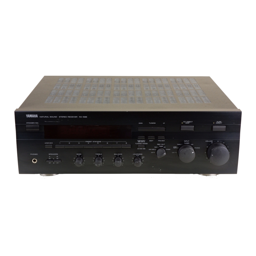
CONTROLS AND THEIR FUNCTIONS FRONT PANEL NATURAL SOUND STEREO RECEIVER RX 596 STANDBY/ON PRESET MEMORY A/B/C/D/E PHONES SPEAKERS BASS STANDBY/ON switch Press this switch to turn on the power to this unit. Press it again to turn this unit into the standby mode. Standby mode In this state, this unit consumes a very small quantity of power to receive infrared-signals from the remote control... - Page 12 PHONES jack When you listen with headphones, connect the headphones to the PHONES jack. When listening with headphones privately, set both the SPEAKERS A and B switches to the OFF position. PHONES SPEAKERS switches Set the switch A or B (or both A and B) for the speaker system (connected to this unit) you will use to the ON position.
-
Page 13: Display Panel
DISPLAY PANEL Multi-information display Displays various information, for example station frequency, preset station number and name of selected input source. STEREO indicator Lights up when an FM stereo broadcast with sufficient signal strength is received. Signal-level meter Indicates the signal level of the received station. If multipath interference is detected, the indication decreases. -
Page 14: Remote Control Transmitter
The remote control transmitter provided with this unit is designed to control all the most commonly used functions of this unit. If the CD player and tape deck connected to this unit are YAMAHA components designed for remote control compatibility, this remote control transmitter will also control various functions of each component. -
Page 15: Basic Operations
From page 13 to 19, this manual describes how to operate this unit mainly by using the front panel control parts. To operate this unit on the remote control transmitter, use the corresponding keys on the remote control transmitter. TO PLAY A SOURCE STANDBY/ON PHONES VOLUME... - Page 16 TO RECORD A SOURCE TO TAPE (OR MD) Select the source you want to record. REC OUT TUNER TAPE 1 VCR/TAPE 2 LD/TV Play the source. Confirm the source by selecting it with the INPUT selector and turning up the VOLUME control. INPUT TUNER TAPE 1...
-
Page 17: Selecting The Speaker System
Adjusting the BALANCE control Adjust the balance of the output volume to the left and right speakers to compensate for sound imbalance caused from speaker location or listening room conditions. BALANCE Adjusting the BASS and TREBLE controls BASS TREBLE BASS : Turn this clockwise to increase (or counter- clockwise to decrease) the low frequency response. -
Page 18: Tuning Operations
Normally, if station signals are strong and there is no interference, quick automatic-search tuning (AUTOMATIC TUNING) is possible. However, if signals of the station you want to select are weak, you must tune to it manually (MANUAL TUNING). AUTOMATIC TUNING Select “TUNER”... -
Page 19: Preset Tuning
MANUAL PRESET TUNING This unit can store station frequencies selected by tuning operation. With this function, you can recall any desired station only by selecting the preset station number where it is stored. Up to 40 stations (8 stations x 5 groups) can be stored. STANDBY/ON PHONES To store stations... - Page 20 AUTOMATIC PRESET TUNING You can make use of an automatic preset tuning function for FM stations. With this function, this unit performs automatic tuning and stores FM stations with strong signals sequentially. Up to 40 stations are stored automatically in the same way as in the manual preset tuning method on page 17.
-
Page 21: Exchanging Preset Stations
EXCHANGING PRESET STATIONS You can exchange the places of two preset stations with each other as shown below. Example) If you want to shift the preset station on E1 to A5, and vice versa. Recall the preset station on E1 (by following the method of “To recall a preset station”... -
Page 22: Troubleshooting
If the unit fails to operate normally, check the following points to determine whether the fault can be corrected by the simple measures suggested. If it cannot be corrected, or if the fault is not listed in the SYMPTOM column, disconnect the power cord and contact your authorized YAMAHA dealer or service center for help. SYMPTOM The unit fails to turn on when the STANDBY/ON switch is pressed. -
Page 23: Specifications
AUDIO SECTION Minimum RMS Output Power per Channel 8 ohms, 20 Hz to 20 kHz, 0.025% THD ...80W+80W 6 ohms, 20 Hz to 20 kHz, 0.05% THD ...90W+90W Maximum Power (EIAJ) [General model only] 8 ohms, 1 kHz, 10% THD...130W 6 ohms, 1 kHz, 10% THD...150W Dynamic Power per Channel (by IHF Dynamic Headroom measuring... - Page 24 YAMAHA ELECTRONIQUE FRANCE S.A. RUE AMBROISE CROIZAT BP70 CROISSY-BEAUBOURG 77312 MARNE-LA-VALLEE CEDEX02, FRANCE YAMAHA ELECTRONICS (UK) LTD. YAMAHA HOUSE, 200 RICKMANSWORTH ROAD WATFORD, HERTS WD1 7JS, ENGLAND YAMAHA SCANDINAVIA A.B. J A WETTERGRENS GATA 1, BOX 30053, 400 43 VÄSTRA FRÖLUNDA, SWEDEN VZ85310 Printed in Malaysia YAMAHA MUSIC AUSTRALIA PTY, LTD.