Yamaha EX5 Owner's Manual
Music synthesizer / realtime control / extended synthesis / tone generator / realtime control / extended synthesis
Hide thumbs
Also See for EX5:
- Owner's manual (41 pages) ,
- Supplementary manual (4 pages) ,
- Data list (56 pages)
Table of Contents
Advertisement
Quick Links
See also:
Data List
Advertisement
Chapters
Table of Contents

Related Manuals for Yamaha EX5


Summary of Contents for Yamaha EX5
- Page 1 MUSIC SYNTHESIZER/REALTIME CONTROL/EXTENDED SYNTHESIS MUSIC SYNTHESIZER/REALTIME CONTROL/EXTENDED SYNTHESIS TONE GENERATOR/REALTIME CONTROL/EXTENDED SYNTHESIS TONE GENERATOR/REALTIME CONTROL/EXTENDED SYNTHESIS OWNER’S MANUAL OWNER’S MANUAL...
-
Page 2: Special Message Section
SPECIFICATIONS SUBJECT TO CHANGE: The information contained in this manual is believed to be correct at the time of printing. However, Yamaha reserves the right to change or modify any of the specifications without notice or obligation to update existing units. -
Page 3: Important Safety Instructions
Please make sure that benches are stable and any optional fixtures (where applicable) are well secured BEFORE using. Benches supplied by Yamaha are designed for seating only. No other uses are recommended. - Page 4 Compliance with FCC regulations does not guarantee that interference will not * This applies only to products distributed by YAMAHA CORPORATION OF AMERICA. ADVARSEL! Lithiumbatteri—Eksplosionsfare ved fejlagtig håndtering. Udskiftning må...
- Page 5 • Always save data to a floppy disk frequently, in order to help prevent the loss of important data due to a malfunction or user operating error. Yamaha cannot be held responsible for damage caused by improper use or modifications to the instrument, or data that is lost or destroyed.
-
Page 6: About The Manual
Introductory Section This section has been designed to provide you with an overall understanding of the EX5, EX5R, and EX7, as well as some hints as how to use these advanced instruments most effectively. It will also refer you to corresponding sections in the Reference section, so you can refer to the pertinent details as necessary. -
Page 7: Table Of Contents
The Supplied Disks, Demos, & Factory Set Data ...25 EX System Overview ...28 Extended Synthesis ...29 AWM Synthesis ...29 Virtual Acoustic Synthesis (EX5/5R) ...30 AN Synthesis (Analog Physical Modeling)...33 FDSP Synthesis (Formulated Digital Signal Processing) ...34 Voice and Performance Selection...36 Voice Structure &... -
Page 8: Introductory Section
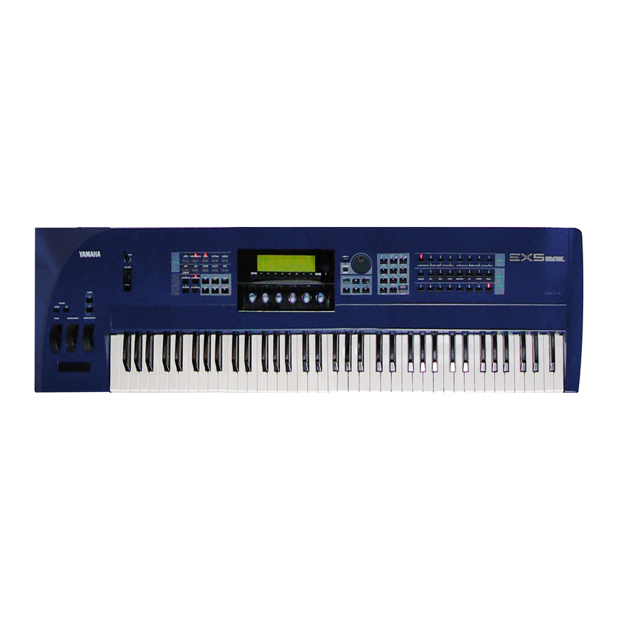
Front Panel EX5/7 1 OCTAVE [DOWN] and [UP] Keys (EX5 and EX7 only) Shift the pitch of the keyboard up or down up to five octaves in one-octave steps. The pitch is shifted one octave in the corresponding direction, up to the maximum, each time one of these keys is pressed. - Page 9 Adjusts the volume of the sound delivered via the rear-panel OUTPUT L/MONO and R jacks as well as the PHONES jack. 8 Keyboard (EX5 and EX7 only) The EX5 has a 76-key keyboard while the EX7 has a 61-key keyboard. Both are velocity and after-touch sensitive for broad, intimate expressive control. EX5R...
- Page 10 EX5/7 ) [KNOB MODE] Key ([KNOB] on the EX5R) The six Controller Knobs, described below, can function either as sound controllers or data entry knobs. In the Song, Pattern, Sample, Edit, Job, Store, Utility and Disk modes the [KNOB MODE] key switches between data entry...
-
Page 11: Controller Knobs
System Exclusive message is being received. [ [SONG] The Song mode provides access to the sophisticated sequence recording, playback, and editing capabilities provided by the EX5, EX5R, and EX7. page 185] [PATTERN] Sequence “patterns” which can be used individually or incorporated into complete songs in the Song mode can be recorded, played, and edited in the Pattern mode. - Page 12 EX5/7 ( Data Dial and [CURSOR/DATA] Key The Data Dial provides a fast, efficient way to cover a broad range of voice numbers when, for example, you’re looking for a voice but don’t know the number. It's also handy for making large value changes in any of the editing and utility modes.
- Page 13 ¢ Bank [A] Through [H] Keys (EX5 and EX7 only) Each of the EX5 and EX7 voice memories — P1 (Preset 1), P2 (Preset 2), I1 (Internal 1) and I2 (Internal 2) — has 128 voice memory locations arranged in 8 banks of 16 voices MUSIC SYNTHESIZER each.
-
Page 14: Rear Panel
OUT connectors transmit data corresponding to all EX performance and playback operations. The EX5 is equipped with two sets of MIDI terminals: MIDI A and MIDI B. The MIDI A group includes MIDI IN, OUT, and THRU terminals, while the MIDI B group only has MIDI IN and OUT terminals. - Page 15 PHONES Jack Accepts a standard pair of These are the main stereo outputs from stereo headphones (1/4" the EX5, EX5R, and EX7. Be sure to stereo phone plug) for connect both outputs to the appropriate headphone monitoring of channels of a stereo sound system in order...
-
Page 16: Setting Up
WARNING! Make sure your EX5, EX5R, or EX7 is rated for the AC voltage supplied in the area in which it is to be used (as listed on the rear panel). Connecting the unit to the wrong AC supply can cause serious damage to the internal circuitry and may even pose a shock hazard! Use only the AC power cord supplied with the EX5, EX5R, or EX7. -
Page 17: Breath Controller
External Controllers In addition to the many realtime controllers provided on the EX5 and EX7 panel (the PITCH wheel, MODULATION 1 wheel, MODULATION 2 wheel and Ribbon Controller), plus the six Controller Knobs provided on the EX5, EX5R and EX7, a number of additional controllers can be plugged into the appropriate rear-panel jacks as required. -
Page 18: Audio Connections
Recommended Yamaha headphones for EX monitoring are the HPE-170, HPE-160, or HPE-150 Stereo Headphones. Any standard pair of stereo headphones with a 1/4" stereo phone plug can be used. -
Page 19: Mixing Console
Mixing Console In addition to the stereo OUTPUT L/MONO and R jacks, the EX5 and EX5R initially have two individual outputs: the INDIVIDUAL OUTPUT 1 and 2 jacks. An additional four individual outputs (3 through 6) can be added by installing the optional EXIDO1 Individual Output Board. -
Page 20: Digital Audio (Option)
This allows the EX sound to be recorded or processed with maximum quality. The EXDGO1 Digital Output Board also includes a WORD CLOCK IN connector for precise digital audio synchronization with the external digital devices. EX5/7 EX5R AC INLET See page 278 for details on installation of the EXDGO1 Digital Output Board. -
Page 21: External Sampling Sources
REALTIME CONTROL SCSI Interface (Option) When the optional ASIB1 SCSI Interface Board is installed (see page 278) the EX5, EX5R, or EX7 can be connected directly to an external SCSI data storage device for high-speed, high-volume data storage and retrieval, and/or to a personal computer to allow data transfer between the EX and the Yamaha Wave Editor application (separately available) running on the computer. -
Page 22: Midi Connections
Please note that since the EX5, EX5R, and EX7 use a proprietary data format, the external hard disk must be formatted by the EX5, EX5R, or EX7 to allow direct data storage and retrieval. The EX5, EX5R, or EX7 will not directly write to or read from a hard disk formatted by any other computer or device, and vice-versa. - Page 23 For detailed MIDI specifications refer to the “MIDI Data Format” in the Data List book. When using the EX5, EX5R, or EX7 with other MIDI equipment, it is a good idea to refer to the MIDI specifications (implementation chart, MIDI data format) of the equipment used to ensure compatibility.
-
Page 24: Power-On Procedure
ON or OFF. This can interfere with operation of other MIDI equipment connected to the EX MIDI OUT connectors. If the EX5, EX5R, or EX7 is transmitting MIDI data to other MIDI equipment, the EX power switch should be turned ON before, and turned OFF after the power switche(s) of the receiving MIDI device(s). -
Page 25: Load And Play The Demo Songs
The Supplied Disks, Demos & Factory Set Data The EX5, EX5R, and EX7 are supplied with four Demonstration Disks containing various types of pre-programmed demo data which will give you an idea of some of their advanced capabilities, as well as provide a number of programming examples that may help you to create the type of sound you need. - Page 26 Select File Load Press the [F2] function key to go to the File Load menu. Select All Data Press the [F1] function key to select All Data. Please note that all-data files have the suffix “.S1A” appended to the file name. Select a file and load Use the Data Dial, [DEC]/[INC] keys, or numeric keypad to select a file number (all of the files on the Demonstration disk contain different demo songs), then press the [ENTER] key.
-
Page 27: Restoring The Factory Set Data
Restoring the Factory Set Data In addition to the preset voices (which cannot be erased or overwritten), the EX5, EX5R, and EX7 come with a range of pre-programmed voices, performance setups, and other data in memory. If you perform any operations that overwrite the data in memory (including system initialization, below), the factory preset data will be lost. -
Page 28: Ex System Overview
MIDI master keyboard or other MIDI controller. The sequencers: Song, Pattern, and Arpeggiator. The EX5, EX5R and EX7 feature and range of sequencing functions that give them many of the capabilities of a sophisticated music production system without the need for any extra equipment. -
Page 29: Extended Synthesis
AWM synthesis, it is there. When you need the unmatched playability and musical response of VL synthesis (EX5 and EX5R only), it is right at your fingertips. When you want a beefy analog synthesizer voice, you don’t even have to change keyboards. -
Page 30: Virtual Acoustic Synthesis (Ex5/5R)
One of the remarkable features of the Virtual Acoustic Synthesis system is that just about any driver can be used with any type of pipe or string. The EX5/5R provides a range of 272 preset VL “waves” which integrate all of the necessary characteristics, and which can be assigned to voice elements in much the same way as AWM waves (VL voices can have 1 VL element plus up to 3 AWM elements). -
Page 31: Controllers & Modifiers
In essence, the controller parameters determine how the instrument “plays.” All of these parameters can be assigned to any external controller that can be used with the EX5 and EX5R: Foot Controller, Modulation Wheel, Controller Knobs, Ribbon Controller, Breath Controller, etc. -
Page 32: Vl System Overview
VL System Overview Element Driver Mouthpiece Embouchure Bow (for strings) Pipe/String Pipe (Single-ended) Pipe (Double-ended) String VL + AWM Voices A single VL element can be combined with up to three AWM elements. Elements Modifier Effect Effects... -
Page 33: An Synthesis (Analog Physical Modeling)
FM synthesis similar to the type that made the legendary Yamaha DX7 one of the most popular synthesizers of all time. In addition to single-element AN voices, the EX5 and EX5R allow two AN elements to be layered to create even thicker analog synth sounds. -
Page 34: Fdsp Synthesis
As shown in the diagrams below, a single AN element can be combined with up to three AWM elements in AN(Poly)+AWM voices. In the EX5 and EX5R, two AN elements can be combined with up to two AWM elements in AN(Layer)+AWM Voices. AN + FDSP voices are described in the FDSP Synthesis section, below. -
Page 35: Fdsp Voice Element Structure
FDSP Voice Element Structure In an FDSP voice up to four AWM elements can be fed to the FDSP stage or routed directly to the normal effect stage as required. Elements AN+FDSP Voices AN+FDSP voices allow a single AN element to be layered with up to three AWM elements feeding the FDSP stage. -
Page 36: Voice And Performance Selection
Voice & Performance Selection One of the first things you'll want to do with your EX5, EX5R, or EX7 is select and play some of its voices or performance combinations … this section will show you how to do just that. - Page 37 Each memory area contains 8 banks of 16 voices each (8 x 16 = 128). The Performance mode has just one 128-location memory area. On the EX5 and EX7, any voice or performance in the current memory area can be selected by specifying its bank using the BANK keys ([A] through [H]), and its number using the PROGRAM number keys ([1] through [16]).
-
Page 38: Alternate Selection Methods
Alternate Selection Methods The [INC] and [DEC] Keys The [INC] and [DEC] Keys are best used for small, step-wise changes — e.g. selecting adjacent voice or performance numbers, or numbers that are only a few steps away. Press the [DEC] or [INC] key briefly to decrement or increment the number by one, or hold either key for continuous decrementing or incrementing in the corresponding direction. - Page 39 The DSP (Digital Signal Processing) system used to create the EX effects is also used by the AN, FDSP, and VL (EX5/5R only) tone generators to create voices. This means that less DSP capacity is available to produce effects when the aforementioned voice types are used. This imposes limitations which are different for the EX5/5R and EX7.
-
Page 40: Voice Structure & Editing Hints
In an AWM element, the “oscillator” is the waveform or sample on which the voice is based. In a VL element (EX5/5R only), it is the instrument model: the reed/mouthpiece, lip/mouthpiece, or bow/string system plus the resonant system corresponding to the tube and air column or string. - Page 41 PITCH The PITCH stage determines the pitch of the sound. In addition to allowing the pitch of the voice to be controlled from the keyboard or via MIDI note data, it allows pitch control from the pitch bend wheel, keyboard aftertouch, or any other assignable controller. The PITCH stage also includes programmable pitch envelope generators which can be programmed to produce time-based pitch variation, as well as key scaling parameters which can be used to produce different tuning curves.
-
Page 42: Overall System Structure
FILTER, and AMPLITUDE stages of each element, as well as the EFFECT block. KEYBOARD, CONTROLLERS & LFO The EX5 and EX7 keyboards include both initial and aftertouch response which can be used for realtime control of an extremely wide range of parameters. The EX5R does not have a keyboard, but it accepts corresponding MIDI data from an external device which can be used to the same effect. -
Page 43: Element Configuration
The type of element(s) you use will always be your first decision when creating a new voice. AWM Voices (EX5, EX5R, and EX7) AWM voices can have from 1 to 4 AMW elements. If you’re creating an AWM voice, this is obviously the type to choose. - Page 44 AN(Poly) Voices (EX5, EX5R, and EX7) A standard (Poly) AN voice can have 1 AN element and from 1 to 3 AWM elements. If you’re striving to create a classic analog synth or FM synthesizer type sound, it is probably better to start with the single AN element alone.
-
Page 45: Polyphony
AWM ELEMENT Polyphony The maximum polyphony of the EX5 and EX5R is 126 notes, and the maximum polyphony of the EX7 is 64 notes. Full polyphony, however, is not available for all voice types. The chart below lists the maximum polyphony for each voice type. -
Page 46: Element Muting
“mute” any other elements so you can hear only the target element while making subtle changes. On the EX5 and EX7 individual element muting can be accomplished via BANK select keys [5] through [8] (labelled “ELEMENT ON/OFF). The key indicators corresponding to elements which are on will be lit, and will go out when the corresponding element is muted. -
Page 47: Relative & Absolute Controller Knob Data Entry
Relative & Absolute Controller Knob Data Entry Normally when you rotate a Controller Knob being used for data entry, the corresponding value changes in relative fashion — i.e. the knob increases or decreases the value of the parameter in relation to the value that was initially on the display. To put it another way, the central detented position of the Controller Knob will correspond approximately to the parameter value that was on the display before the knob was rotated. -
Page 48: Voice Store Procedure
Use the Cursor keys in conjunction with the Data Dial, the [DEC]/[INC] keys, the numeric keypad, or Controller Knob 1 to select the internal Voice memory location to which you want to store the edited data. The BANK and PROGRAM keys can also be used on the EX5 and EX7. Press [ENTER] and confirm Press the [ENTER] key. -
Page 49: The Power Of The Performance Mode
The Power of the Performance Mode The EX Performance mode allows up to 16 different voices to be assigned to different “parts” and combined in a number of ways. The results can be ideal for real-time performance — as the name of the mode suggests —... -
Page 50: Velocity Switching
Split Keyboard Instead of layering voice parts over the same keyboard range, different parts can be assigned to different areas of the keyboard for split keyboard setups. A simple example would be to assign a bass voice to the left-hand section of the keyboard and a piano voice to the right-hand section. The Note Limit parameters in the Performance Edit mode are used to assign the various parts to the required note ranges (page 166). -
Page 51: Arpeggiator Accompaniment
Arpeggiator Accompaniment The EX Arpeggiator (page 61) is capable of producing an essentially unlimited range of patterns which can be tailored to make ideal accompaniment for a wide spectrum of musical styles. The Arpeggiator can be assigned to any of the Performance mode parts, so in a split-keyboard setup you could control an Arpeggiator pattern with the left hand while playing a lead line with the right. -
Page 52: Voice Editing From The Performance Mode
Voice Editing From the Performance Mode There may be times when you’ll want to actually edit a voice being used in the Performance mode rather than just the Performance parameters. You can jump directly to the Voice Edit mode from the Performance or Performance Edit mode by pressing the [VOICE] key while holding the [PERFORMANCE] key. -
Page 53: Performance Store Procedure
Use the Data Dial, the [DEC]/[INC] keys, the numeric keypad, or Controller Knob 1 to select the Performance memory location to which you want to store the edited data. The BANK and PROGRAM keys can also be used on the EX5 and EX7. Press [ENTER] and confirm Press the [ENTER] key. -
Page 54: Performance Mode Dsp Limitations
The DSP (Digital Signal Processing) system used to create the EX effects is also used by the AN, FDSP, and VL (EX5/5R only) tone generators to create voices. This means that less DSP capacity is available to produce effects when the aforementioned voice types are used. This imposes limitations which are different for the EX5/5R and EX7. -
Page 55: The Controllers
The EX Controllers All of the controllers that can be used with the EX5 and EX7 are listed below. Since the EX5R is a tone generator, it does not have many of the physical controllers provided on the keyboard models. -
Page 56: Extended Midi Control Capability
Voice Play and Performance Play modes. Breath Controller (EX5/EX5R/EX7) An optional Yamaha BC3 Breath Controller plugged into the rear-panel BREATH jack can be assigned to control any of the available EX parameters — but it is a natural candidate for controlling Pressure, Tonguing, Throat, Growl, and other VL tone generator parameters. -
Page 57: Scene Switching & Morphing
Controller Knob settings will again take effect. While either scene is active, you can switch directly to the other scene by pressing its key — the indicator of the previously active scene key will go out and the new scene indicator will light. SCENE EX5/7 EX5R SAMPLE DISK... -
Page 58: Controller Sets
Scene Control (Scene Morphing) The term “morph” comes from the word “metamorphosis,” meaning to change from one form or shape to another. In the case of the EX scenes it means to change gradually and smoothly from one scene to another, instead of switching abruptly as described in the preceding section. To morph between scenes, first press one SCENE key while holding the other so that both SCENE indicators light simultaneously. -
Page 59: Controller Set Remapping
The source controllers are: Display Abbreviation The destination parameters are organized into 8 related groups, listed below. The actual parameters available in each group for a given voice will depend to some extent on the type of voice and how it is set up, the type of effects selected, etc. -
Page 60: Sequencer Functions
Sequencer Functions The EX5, EX5R, and EX7 have three separate sequencing functions suited to different purposes: The Song Mode The EX Song Sequencer is a full-featured 16-track sequencer complete with real-time play effects — including “groove” quantization — and a comprehensive range of editing functions. A 30,000 note memory gives this sequencer plenty of capacity for recording and playback of complete songs with rich musical textures and complex arrangements. -
Page 61: The Arpeggiator
The Arpeggiator 4-track arpeggio patterns — from simple to sophisticated — can be stored as performance parameters for automatic recall and use with individual performance setups, or used with voices in the Voice mode. The EX Arpeggiator makes it easy to create automatic arpeggios, techno-style patterns, or a virtually unlimited range of other repeating phrases. -
Page 62: Sequence Record Modes & Editing
ARPEGGIO Replace In the “Replace” real-time record mode the EX5, EX5R, or EX7 records exactly what you play as you play it, erasing any previous material in the record track as you do so. This is the mode you’ll usually use when recording a new track “from scratch.” The fact that you’re recording in real-time means that all the subtle timing and nuances of your performance will be accurately recorded (as well as the mistakes). -
Page 63: Sequence Editing
This can be used if, for example, you need to record an entire sequence from an external sequencer or computer via MIDI. On the EX5 and EX7 to record one track form the EX keyboard while recording the rest via MIDI. -
Page 64: Play Effects & Groove Quantization
Play Effects & Groove Quantization An important feature of all EX sequencer functions is “Play Effects,” … including “Groove Quantization.” Play Effects affect song, pattern, or arpeggio playback in real time, and are not actually recorded with the sequence data. The Play Effects include Groove Quantization and a range of offset parameters affecting overall clock timing, velocity, gate time, and transposition. -
Page 65: The Ex Effect System
In the EX5, EX5R, and EX7, effect programming is an integral and important part of voice programming, and the ability to control specific effect parameters in real time makes them indispensable for expressive control as well. - Page 66 Insertion Effects Two insertion effect units are provided in addition to the Reverb and Chorus system effect units described above. The Effect 1 unit includes 24 effects including chorus, distortion and overdrive, amp simulation, auto wah, equalization and more. The Effect 2 unit adds a range delay, reverb, and other effects, providing a total of 79 effects.
-
Page 67: Effects In The Performance Mode
Effects In the Performance Mode In the Performance mode the insertion effects apply to the voices exactly as they were set up in the Voice mode. The Voice mode Reverb and Chorus unit settings, however, are not used in the Performance mode. - Page 68 The DSP (Digital Signal Processing) system used to create the EX effects is also used by the AN, FDSP, and VL (EX5/5R only) tone generators to create voices. This means that less DSP capacity is available to produce effects when the aforementioned voice types are used. This imposes limitations which are different for the EX5/5R and EX7.
-
Page 69: Sampling
— to the EX5, EX5R, or EX7. If you will be using a single microphone, connect it to the L/MONO A/D INPUT jack on the EX5 or EX5R (the EX7 only has a single A/D INPUT jack). If you will be using a pair of microphones with the EX5 or EX5R, connect them to the L/MONO and R A/D INPUT jacks. -
Page 70: Record Mode & Input Settings
SAMPLE REC display. If you are sampling with an EX5 or EX5R, you will need to set the Rec Mode parameter for mono or stereo sampling (this is not necessary with the EX7, since it has a MONO A/D INPUT):... -
Page 71: Recording The Sample
Length parameter, or until the end of the sample memory is reached, if not stopped manually. The EX5, EX5R, and EX7 record at a sample rate of 44.1 kHz. See page 176 for details on sampling from the internal tone generators. -
Page 72: The Key Map Mode
(or MIDI note numbers in the case of the EX5R). The assigned samples and/or patterns can then be played via the EX5/EX7, or via an external sequencer or other MIDI controller on all models. Key Mapping makes it possible, for example, to combine playback of looped rhythm samples with patterns to create new rhythmic textures that can be controlled “live,”... - Page 73 Specify a pattern or sample If you chose to map a pattern to the selected note, use the cursor keys in conjunction with the Data Dial, [DEC]/[INC] keys, or appropriate Controller Knobs to specify a track — “Tr1 … Tr8” for an individual track, or “all”...
- Page 74 About The Tune Screen Pressing the [F2] key selects the Tune screen, which is only available for samples and includes two tune-related parameters: Coarse and Fine. Coarse: Raises or lowers the pitch of each sample in semitone steps. Settings: -64~+63 Fine: Allows fine adjustment of the pitch of each element.
-
Page 75: Reference Section
Reference Section Voice Mode Voice Play Mode Voice Play Mode lets you play the 256 Preset Voices and User Voices of your own creation. Voice Play Mode screen Press [VOICE] key on the panel to enter Voice Play mode. When you enter Voice Play mode, the following screen appears. -
Page 76: Voice Edit Mode
Voice Category/Name Voice Category The respective voices are organized into the two-letter-code Voice Categories. Each Category code implies the voice’s property. Category Category No Assign Synth Pad Piano Synth Sound Effects Chromatic Percussion Ethnic Organ Percussive Guitar Sound Effects Bass Drums Strings/Orchestral Synth Comping... -
Page 77: Normal+[Edit] A Wm Element
Uses up to a maximum of four AWM elements. AWM elements are digitally recorded waveforms, or “samples” of musical instrument and other sounds. VL+AWM (EX5/5R only): Uses one VL element for Virtual Acoustic synthesis, plus three AWM elements. Once the VL voice type is selected, the first element in the OSC screen (page 108) is fixed to the VL element. - Page 78 For more information about VL, see page 30; FDSP: page 34; Analog: page 33; Drum: page 39. Polyphony The maximum polyphony of the EX5 and EX5R is 126 notes, and the maximum polyphony of the EX7 is 64 notes. Full polyphony, however, is not available for all voice types.
-
Page 79: [F7:Arpeggio]
Mono/Poly Selects whether the voice is played monophonically (only one note at a time) or polyphonically (multiple notes sounding simultaneously). Settings: mono, poly Key Assign Selects sngl (single) or mlti (multi) Key Assign. In sngl (single), if the tone generator receives the same note twice, the first note is terminated when the next same note is received again. -
Page 80: [F2:Oscillator]
Setting the Voice Name 1 Press [F8] to enter the Name screen. 2 Move the [ ] cursor to the far left with the Cursor key. 3 Use [INC]/[DEC] or Data Dial to select the Category. The category names help you to sort the voices you have created. -
Page 81: [F3:Wave-Edit]
This is the same as "FwdLp" as long as the key is held. However, when you release your finger from the keyboard, the Ex5/5R/7 cancels the loop playback, goes beyond the End point, and plays the rest of the sample data, then stops at the data end. -
Page 82: [F8:Zone]
[F8]: ZONE Sets the zone of each element (the keyboard and velocity ranges within which the sounds are played). A different zone can be set for each element. Note Limit Low Sets the lowest note of the zone on the keyboard, for each element. -
Page 83: [F3:Pitch]
[F3]: PITCH The Pitch parameters adjust the pitch of the wave and configures the tuning system. There are three menus with various parameters that can be applied to each element. [F6]: PARAM (Parameters) [F7]: SCALE [F8]: EG (Envelope Generator) [F6]: PARAM (Parameters) Adjusts each wave’s tuning and the PEG settings. -
Page 84: [F8:Eg]
Micro Tuning Sets the Micro Tuning (tuning system, or temperament) each element will use. Beginning with the standard tuning “equal temperament,” there are 32 tuning systems available. Settings: Each system is listed below. Type Comments The “compromise” tuning used for most of Equal temperament —... - Page 85 Time Scale The Time Scale function determines the speed of change in the PEG according to the pitch played on the keyboard. When the Time Scale is set to a positive value, the lower the note played on the keyboard, the slower the change that occurs over time.
-
Page 86: [F4:Filter]
A different filtration can be set for each element. The EX5/5R/7 has two other filters that make it possible to create a wide range of sounds. These are two sets of DCF (Dynamic Control Filter) filters. For information, see page 91. -
Page 87: L Shelf (2-Low Shelving Filter)
High/Low Gain Vel (High/Low Gain Velocity) Sets the velocity sensitivity for signal levels designated by the High Gain and Low Gain. When the High/Low Gain Vel is set to a positive value, the harder a note is played on the keyboard, the more the amount of gain is applied. - Page 88 High1/2 Gain Sets the signal levels for the frequencies passing above the High1/2 Freq points. Settings: –16~0~+16 High1/2 Gain Vel (High1/2 Gain Velocity) Sets the velocity sensitivity for signal levels designated by the High1/2 Gain parameter. When High1/2 Gain Vel is set to a positive value, the harder a note is played on the keyboard, the more the gain that is applied.
- Page 89 HPF (High Pass Filter) The HPF passes the signals above the specified cutoff frequency set in the Freq parameter (below), and cuts the signals below it. Level Cutoff Range passed range Cutoff frequency Freq (Frequency) Sets the cutoff frequency. This determines the cutoff frequency of the filter, or the frequency below which all other frequencies are filtered out.
-
Page 90: Peq (Parametric Equalizer)
PEQ (Parametric Equalizer) The PEQ increases or decreases the signal levels around the frequency designated in Freq (see below) using the Gain parameter. Gain – Freg Freq (Frequency) Sets the center frequency. The signal levels of the band of frequencies designated here can be increased or decreased by the Q setting. -
Page 91: [F5:Dinamic Control Filter]
[F5]: DCF (Dynamic Control Filter) Configures the parameters for the Dynamic Control Filter. There are various kinds of filters that change the timbre of the sound by passing only specific frequencies through from the harmonic contents (other frequencies are filtered out). A different filtration can be applied to each element. -
Page 92: Thru Gain
Thru Gain Determines the amount of the signals that does not pass through the filter, or the original dry sound. Settings: 0~255 The Thru Gain is displayed and effective only when a filter type other than LPF24A, LPF24D, LPF18 and Thru is selected, and the Connect setting (see below) is set to seri (serial). -
Page 93: [F6:Sensitivity]
LPF6(Low Pass Filter 6): -6dB/oct low pass filter-type digital dynamic filter with no resonance. LPF6 HPF (High Pass Filter) The HPF filter passes the signals above the specified cutoff frequency, and cuts the signals below it. Level Cutoff range Range passed Cutoff frequency BPF (Band Pass Filter) The BPF filter passes the signals around the specified... -
Page 94: [F7:Scaling]
F1/2 Vel Freq (Filter 1/2 Velocity Frequency) Sets the velocity sensitivity for the cutoff frequency parameter. When F1/2 Vel Freq is set to a positive value, the harder a note is played on the keyboard, the higher the cutoff frequency becomes, and a greater change occurs in the timbre of the sound. -
Page 95: [F8:Eg]
[F8]: EG (Filter Envelope Generator) Sets the FEG, which determines how the timbre of the sound will change over time, from when the key is pressed, held, then released. The FEG is effective for both DCF1/2, and different settings can be made for each element. -
Page 96: [F5:Amplitude]
L (Loop) Sets the loop point for the FEG. As seen in the FOLLOWING diagram, this function sets the position to be returned to after reaching the Decay 2 (loop point). Selecting “off” turns the loop function off. Filter EG Loop Point Loop Loop... -
Page 97: [F7:Scaling]
Level KeyFollow Sets the Level KeyFollow for each element. The Level KeyFollow function determines the output level in accordance with the notes played on the keyboard. When Level KeyFollow is applied, the output level is increased or decreased relative to the basic pitch, which is designated here as C3. -
Page 98: [F8:Eg]
Setting the Amplitude Scaling You can set the note (pitch) and the offset level for each break point (BP1-4), as shown in the following example. In this example, E1 has a level of –4. This means that the present output level is 76, because 80-4 equals 76. -
Page 99: Decay Level Vel (Decay Level Velocity)
Decay Level Vel (Decay Level Velocity) Increase or decrease the Decay Level with the velocity. Settings: –7~0~+7 Attack Mode Selects the Attack Mode (1 or 2) or switches back and forth between modes. Settings: 1 (Attack Mode 1), 2 (Attack Mode 2) More information about each mode is provided below. -
Page 100: [F6:Lfo]
[F6]: LFO (Low Frequency Oscillator) The LFO parameters set the LFO. The LFO oscillator generates low frequency signals that allow for modulation to be applied to specific aspects of the voice. Applying an LFO wave (shape of modulation) to the pitch, filter, or amplitude creates effects such as vibrato, waw, and tremolo. - Page 101 Fade Sets the fade-in effect of the LFO after the designated delay time has passed. As shown in the diagram below, the larger the value, the longer it takes for the LFO effect to reach the peak in modulation. Settings: 0~255 Fade Key on Delay...
-
Page 102: [F8:Lfo2]
AMD (Amplitude Modulation Depth) Determines how greatly the LFO will affect the output level. Larger values widen the range of the volume change. Settings: 0~127 PMD (Pitch Modulation Depth) Determines how greatly the LFO will affect the pitch. Larger values widen the range of the change in pitch. -
Page 103: [F7:Controller]
Sync The parameters for LFO2 Sync are the same as for LFO1 Sync. For an explanation, see page 100. Delay The parameters for LFO2 Delay are the same as for LFO1 Delay. For an explanation, see page 100. Fade The parameters for LFO2 Fade are the same as for LFO1 Fade. -
Page 104: [F8:Controller Set]
Port Mode (Portamento Mode) Selects the portamento mode. The way in which the portamento moves will differ depending on whether the Mono or Poly parameter is selected in the Common menu. Settings: fngr (fingered), full When “Mono” is selected in the Common menu: fngr (fingered): Portamento is applied only when you play legato (playing a note before releasing the previous one). -
Page 105: [F8:Effect]
Dest Depth (Destination Depth) Sets the depth for the control function selected in Dst Param. Settings: –64~0~63 Assigning Controllers to the Controller Set Due to the 16 voice controller sets, there are many possible combinations. For example, one Src Sw (Source Switch) can control various Destinations Parameter (Dest Param), or various Source Switch (Src Sw) can control a single Dest Param... -
Page 106: [F5:Insertion Effect 1]
InsEF1 (Insertion Effect 1) Selects the type of effect for Insertion Effect 1. Settings: 00 (thru)~24 For more information about each type of effect, see the Effect Type List in the separate Data List book. InsEF2 (Insertion Effect 2) Selects the type of effect for Insertion Effect 2. Settings: 00 (thru)~79 For more information about each type of effect, see the Effect Type List in the separate Data List book. -
Page 107: [F7:Reverb]
Chorus type. For more information, see the Effect Type List in the separate Data List book.) Normal Voice (VL Element) (EX5/5R only) The following explanations include only the differences between the VL Element and the AWM Elements. The remaining functions and parameters are the same as those for the AWM Elements. - Page 108 VL Mono/Poly (VL Monophonic/Polyphonic) Selects how the VL Element produces sound. The VL Element is limited to only one sound at a time. However, as shown below, the way in which sound is produced is different depending on whether “mono” (monophonic) or “poly” (polyphonic) is selected.
- Page 109 [F8]: EG (Pitch Envelope Generator) The following screen appears when the VL Element is selected in the PEG screen. Initial Level Sets the initial pitch of the VL Element when a note is played. When the Initial Level is set to a positive value, the pitch generated will be higher than the correct pitch.
- Page 110 [F8]: DCF (Dynamic Control Filter) Resonance Parameters which let you boost specific frequencies around the cutoff frequency. Settings: –64~0~+63 Cutoff Freq (Cutoff Frequency) Sets the cutoff frequency for the filter. Settings: –64~0~+63 Freq EG Depth (Frequency EG Depth) Sets the depth of the change in the cutoff frequency over time.
- Page 111 Attack Time Sets the amount of time it takes to reach the peak in volume from when a note is played. When Attack Time is set to a positive value, the peak is reached more slowly. Negative values cause the peak to be reached more quickly.
-
Page 112: Normal+[Edit] An Element
With the EX7, only one sound can be produced at a time. The EX5/5R in Poly mode can produce one or two sounds depending on the selected Voice Type. In Poly mode, if two or more keys are held simultaneously, when the first key which currently produces sound is released, the other notes will not be retriggered. -
Page 113: An Priority
AN Priority Determines the priority for notes played as an AN Element. When chords or several notes are played at the same time, you can select which note will sound, as follows: last (the note that was played last), top (the highest note), bottom (the lowest note). - Page 114 Sync Synchronizing the master and slave oscillator in VCO1 will increase the wave harmonics and create a more complex sound. The Sync is automatically set to “on” when an algorithm other than FM is selected. The FM algorithm does not contain the master and slave oscillators but functions just as one VCO.
-
Page 115: Vco1/2 Pitchscale
VCO1/2 PitchScale Sets the Pitch Scale for each VCO1/2 oscillator. The Pitch Scale function corrects the pitch change of VCO1/2 in accordance with the notes played on the keyboard. When VCO1/2 Pitch Scale is applied, the pitch change is increased or decreased relative to the specific pitch, which is designated here as MIDI note number 64 (E3). -
Page 116: Pwm Src (Pulse Width Modulation Source)
In general, the Pulse Width parameter is used to control the width of the pulse (pulse wave); however, it can be used for waves other than the pulse with the EX5/5R/7, providing much more possibilities in sound creation. Settings: 0~64~127 (0%~50%~99%) - Page 117 Bank In the COM PARAM screen (explained above), when the Voice Type, AN (Poly)+AWM or AN+FDSP is selected, the first Element wave is always set as an AN Element. When the Analog Layer is selected, the first and second Elements are always set as an AN Element.
- Page 118 PEG Decay Time Sets the PEG Decay Time. When set to a positive value, this setting determines the amount of time for the sound to reach its basic pitch from the PEG Depth level. When a negative value is set, this setting determines the amount of time starting from the basic pitch to the set PEG Depth level.
- Page 119 [F8]: EG (Filter Envelope Generator) Sets the FEG for the AN Element. You can control the change in the timbre of the sound over time, from when the key is played until it is released. This is effective for VCF 1/2 filters. Time K.Follow (Time KeyFollow) Sets the Time Key Follow for the AN Element.
- Page 120 VCO2 Level Sets the signal level of the wave sent from VCO2 to the mixer. When you do not want to apply the VCO2 signal, set the level to “0.” Settings: 0~127 Noise Level Sets the level of the signal sent from the Noise unit to the mixer.
- Page 121 Release Time This sets the amount of time it takes for the signal to reach “0,” after releasing the key. Settings: 0~127 [F6]: LFO (Low Frequency Oscillator) When an AN Element is selected, there is one type of menu related to LFO settings available. [F8]: LFO (Low Frequency Oscillator) [F8]: LFO (Low Frequency Oscillator) Sets the LFO for the AN Element.
- Page 122 Tri (Triangle) Wave Triangle Triangle Triangle Triangle180 Triangle180 Squ (Square) Wave Square Square Square180 Saw (Sawtooth) Wave Saw down Saw down Saw up Saw up s/h (Sample & Hold) Wave s/h2 s/h2...
-
Page 123: Fdsp
Controller List in the separate Data List book. FDSP (Formulated Digital Sound Processing) When FDSP or AN+FDSP (EX5/5R) is selected as the Voice Type from the PARAM menu (in COM), FDSP menu is added to the bottom of the screen as the [F5] function. - Page 124 Next, the vibration is detected by the pickup opposite to the tine. Then the signal detected by the pickup is modified with the frequency characteristics unique to the electromagnetic pickup, and output. This system incorporates Yamaha’s Virtual Acoustic technology. Drive Magnetic Field...
- Page 125 BP High (Break Point High) Sets the Break Points, which affect the parameters Position and Out Level in accordance with the pitch change, in the note range above C3. Values can be set in semitones from C3, which is regarded as the value of 0.
- Page 126 Next, the vibration is detected by the pickup. Then the signal detected by the pickup is modified with the frequency characteristics unique to the electromagnetic pickup, and output. This system incorporates Yamaha’s Virtual Acoustic technology. note dependent note dependent...
- Page 127 Pickup Type Sets the type of pickup. There are two types, single (single coil), and humback. Settings: single: Produces the projective sounds in the high register, one of the characteristics of a single coil pickup. humback: Produces the mellow and warm sounds unique to a hum backing pickup.
- Page 128 Output Sets the pickup output level. Settings: –48~0~+48 Output KFlw (Output KeyFollow) Sets the KeyFollow for the Output. The Output KeyFollow function controls the pickup output level in accordance with the notes played on the keyboard. When set to a positive value, the higher the note played on the keyboard, the greater the change in the output level becomes.
- Page 129 Freq (Frequency) Sets the central frequency for the Sample & Hold LFO filter modulation. Settings: 0~127 Freq K.Flw(Frequency KeyFollow) Sets the KeyFollow for the filter modulation central frequency. This KeyFollow function controls the change of the central frequency in accordance with the notes played on the keyboard.
-
Page 130: Dry Level
Dry Level Sets the output level for the original input signal. A setting of “0” produces no output. Settings with the negative values reverse the phase of the waveform. Settings: –64~0~+63 The same as the one in the EP Pickup. See page 126 for information. -
Page 131: Eg Shape (Envelope Generator Shape)
LFO Depth (Low Frequency Oscillator Depth) Sets the depth of the LFO wave for the pulse width modulation. When set to “0,” only the EG functions. When set to “32,” the LFO wave ranges from “0” to the extent of the EG amplitude. When set to “64,” the absolute values of LFO wave range between the positive and negative extents of the EG amplitude. - Page 132 EG Time Kflw (Envelope Generator Time KeyFollow) Sets the KeyFollow for the EG Time. This KeyFollow function controls the amount of the EG time in accordance with the notes played on the keyboard. When set to a positive value, the higher the note played on the keyboard, the shorter the EG time becomes.
- Page 133 Decay Time Sets the EG decay time (the time of decay from the maximum level until reaching the sustain level). Settings: 0~127 Decay T.Kf (Decay Time KeyFollow) Sets the KeyFollow for the Decay Time. This KeyFollow function controls the decay time in accordance with the notes played on the keyboard.
- Page 134 KeyFollow Sets the KeyFollow for the peak frequency change. This KeyFollow function controls the first peak frequency in accordance with the notes played on the keyboard. When set to “+32,” the KeyFollow functions at 100% and the peak frequency moves in proportion to the pitch played on the keyboard.
- Page 135 07: Self FM Self FM lets you add extra richer harmonics to the sounds. The mechanism how the Self FM type is formed is as follows: first, input signals are sent to the delay unit. Next, the phases of each signal sent from the delay unit are modulated (phase/frequency) by the input signals themselves, to cause the waves distorted.
- Page 136 LPF K.Flw (Low Pass Filter KeyFollow) Sets the KeyFollow for the Low Pass Filter cutoff frequency. The Low Pass Filter KeyFollow function controls the cutoff frequency in accordance with the notes played on the keyboard. When set to a positive value, the higher the note played on the keyboard, the higher the cutoff frequency becomes.
- Page 137 Drive Sets the depth of the modulation. Settings: 0~127 Drive K.Flw (Drive KeyFollow) Sets the KeyFollow for the Drive. The Drive KeyFollow function controls the depth of the modulation in accordance with the notes played on the keyboard. When set to a positive value, the higher the note played on the keyboard, the deeper the modulation becomes.
- Page 138 Wet Gain Sets the maximum output level for the modulated signal. Settings: 0~127 Wet Vel (Wet Level Velocity) Sets the velocity sensitivity for the Wet Level. This lets you control the output level of the modulated signal by the strength at which you play the keyboard.
- Page 139 PEG Depth (Pitch Envelope Generator Depth) Sets the PEG depth that affects the modulation wave’s pitch. Settings: –64~0~+63 PEG DepthVel (Pitch Envelope Generator Depth Velocity) Sets the velocity sensitivity for the PEG depth. The PEG depth can be controlled by the velocity at which the note played on the keyboard.
- Page 140 The same as the one in the EP Pickup. See page 126 for information. 10: Seismic The Seismic, as its name implies, makes the sounds roar. The input signal is sent to the time-variant low- boost filter, then passed through the overdrive. Since the low-boost amount can be controlled by the EG, Seismic will not only emphasize the bottom of the sounds but provide with a compressor type effect.
-
Page 141: Drum+[Edit]
Overdrive Sets the amount of the over drive. Settings: 0~127 HPF (High Pass Filter) Sets the cutoff frequency which cuts the lower range of the output signals. Settings: 0~127 HPF K.Flw (High Pass Filter KeyFollow) Sets the KeyFollow for the High Pass Filter cutoff frequency. - Page 142 128 AWM Elements can be used to create drum voices (i.e., drum kits). When Drum is selected for Voice Type, the panel ELEMENT SELECT keys 1-4 (EX5/7) for normal voices become inactive. For more information about each voice type, see page 29.
-
Page 143: Drum Key
3 (When setting the layers more than one for a key) Select a layer. When many layers have been assigned to the currently selected key, move the cursor to Layer, select the layer to which you want to assign an element. - Page 144 Settings: PRE (Preset), RAM (DRAM), FLS (Flash Memory) FLS is effective only when an optional EXFLM1 is mounted onto the EX5/5R/7. Sample Number Selects the desired sample number from the sample bank. The category and sample name of the selected sample number are displayed to the right of the number.
- Page 145 Sample Play Sets the way in which the sample will be played. Settings: FwdLp, FwdLpEx, FwdNoLp, RevNoLp, default For more information about each setting, see page 81. Recv Note Off (Receive Note Off) Sets whether or not MIDI Note Off messages for each element will be received or ignored.
- Page 146 For example, when “i1&2” is selected, the L channel will be output from INDIVIDUAL OUTPUT1, and the R channel from INDIVIDUAL OUTPUT2. EX5 is equipped with two Individual Outputs (1 and 2) while EX5R and EX7 are not equipped with the Individual Output. You can increase/equip the Individual Outputs on your instrument by installing an optional Individual Output Board (EXIDO1).
- Page 147 [F4]: FILT (Filter) There are four types of menus related to filters when editing a Drum Voice. The parameters and settings are the same as those for AWM Element. For information, see page 86. [F4]: SCF (Static Control Filter) [F5]: DCF (Dynamic Control Filter) [F6]: SENS (Sensitivity) [F8]: EG (Envelope Generator) [F5]: AMP (Amplitude)
-
Page 148: Voice Job Mode
[F8]: EFCT (Effects) Sets the effects for the drum elements. The signals from the maximum of 128 drum elements can be connected either to Insertion Effect 1 or 2, then sent to the Reverb/Chorus unit. “InsRev” and “InsCho” parameters added to the Type screen allow you to emphasize the effect for specific drum elements. - Page 149 5Press [ENTER]. The following pop-up menu will appear, prompting confirmation of the operation. 6Press [YES] to execute the job. “Completed!” will momentarily appear in the screen indicating that the job was executed and the previous screen will be displayed. Press [NO] to cancel the job. “Executing...”...
-
Page 150: Wave Edit Mode
(D)RAM bank/number is selectable, only when the AWM elements are selected for editing. Press [EXIT] to exit the Wave Edit mode. The EX5/5R/7 returns to the original display (Voice Edit mode). In Wave Edit mode, a sample wave is not changed and therefore not destroyed. -
Page 151: Basic Steps For Wave Edit
Press [EXIT] to exit the Wave Edit mode. The EX5/5R/7 returns to the Voice Edit mode. You can use the Wave Job mode (page 154) to copy already existing waves or to delete unnecessary waves. -
Page 152: Startofs (Start Offset)
This is the same as “FwdLp” as long as the key is held. However, when you release your finger from the keyboard, the Ex5/5R/7 cancels the loop playback, goes beyond the End point, and plays the rest of the sample data, then stops at the data end. - Page 153 [F7]: MIX Sets the mix (output), pan, and other settings related to pitch for each sample which make up a wave. Settings can be made for each layer. The Layer and Sample Bank/Number parameters here are the same as those in the SMPL display. For more information on these parameters, see page 152.
-
Page 154: Wave Job Mode
Zone Graphical Display On the left side of this screen, the zone (keyboard and velocity range at which sound will be produced) is displayed. The note range is indicated by the horizontal axis, while the velocity note range is indicated by the vertical axis. As each parameter value is adjusted, the shape of the black box, which represents the note range, changes accordingly. -
Page 155: Dst Wave (Destination Wave)
Press [YES] to execute the job. “Completed!” will momentarily appear in the screen indicating that the job was executed and the previous screen will be displayed. Press [NO] to cancel the job. “Executing...” will appear when the Wave Job takes some time to execute. -
Page 156: Performance Mode
Performance Mode Performance Play Mode Performance Play mode lets you play the Performances of your own creation in realtime and use the EX5/5R/7 as a powerful multi timbre tone generator using the internal sequencer function (Song mode/Pattern mode) or an external sequencer. -
Page 157: Selecting A Performance
Performance mode. For more information, see page 159. You cannot use two or more AN, FDSP or VL (EX5/5R) voices for a performance. Also, on EX7, if you use an AN or FDSP voice for a part, you cannot use insertion Effect for a voice in the same performance. -
Page 158: Performance Edit Mode
Performance Edit Mode Following are explanations of the parameters related to Performance Edit mode. There are parameters whose settings affect all the parts and parameters which affect each individual part. These settings can be stored in each Performance. Press [EDIT] key on the panel while in Performance mode to enter Performance Edit mode. - Page 159 About the E (Edit) mark Whenever any setting is being made or an operational change is taking place, the “ mark appears in the upper left corner of the screen, next to the part number. This lets you confirm that the currently selected Performance is being edited and has not yet been stored.
- Page 160 Total Volume Sets the overall volume for the performance. The volume for each part will be explained later (see page 164). Settings: 0~127 Kbd/TG Mode (Keyboard/Tone Generator Mode) Configures how the tone generator is connected (the signal flow) when in Performance mode. Select M.KBD (Master Keyboard) when mainly using the keyboard for performing, and select TG (Tone Generator) when mainly used as a tone generator for...
-
Page 161: Arp Sw (Arpeggio Switch)
MIDI OUT A/B when set to “on.” When set to “off,” no notes are output. Settings: on, off Arpeggio MIDI Out A/B is available for EX5. In the case of EX5R and EX7, only a set of Arp MIDI Out is available. -
Page 162: Cho Type (Chorus Type)
Cho Type (Chorus Type) Selects the type of chorus for the Chorus unit. Settings: 00 (off)~17 For information about each type of chorus, see the Effect Type List in the separate Data List book. Cho Rev (Chorus Reverb) Sets the send level of the signal output from the Chorus unit, and then sent to the Reverb unit. - Page 163 [F7]: CTRL (Controller) These settings are related to the Controllers. Beginning with the [PITCH] wheel, the settings that are common to all parts are arranged in a chart-type screen and can be set within the chart. When the CTRL menu is selected with the [F7] key, the following menus are displayed.
-
Page 164: Out Select (Output Select)
In the PART screen and the MLT screen (explained next), the part that you want to edit can easily be displayed using the PART 1-16 keys on the panel (EX5/7 only). Bank (Voice Bank) Selects the Bank which contains the voice you want to use for the part. - Page 165 (MIDI OUT A/B) when set to “on,” and is not sent when set to “off.” Settings: on, off Transmit MIDI Out A/B is available for EX5. In the case of EX5R and EX7, only a set of MIDI Out is available.
- Page 166 ArpeggioSw (Arpeggio Switch) Determines whether the currently selected part will be arpeggiated, or not. Settings: on, off Layer Sw (Layer Switch) Sets the Layer SW to “on” or “off.” When set to “on” you can play two parts in a layer. Settings: on, off When the parts’...
- Page 167 wide: This curve decreases the volume level with a light touch playing and increases the volume level with a heavy touch playing. This lets you produce a wider dynamic range. Volume Keyboard Playing Strength fix: This sets the velocity to a fixed value, and the tone generator will produce sound at that value, regardless of the strength at which the keyboard is played.
-
Page 168: Peg (Pitch Envelope Generator)
Decay Time Sets the amount of time it takes to reach the level set in the Decay Time, from the peak level. When Decay Time is set to a positive value, change occurs more slowly. Negative values cause the change to occur more quickly. -
Page 169: Port (Portamento)
Port (Portamento) Settings related to the Portamento effect of each part. The following three parameters are available. Port Sw (Portamento Switch) Turns the portamento”on” and “off.” Portamento creates a smooth glide in pitch from one note to the next. Settings: off, on Port Time (Portamento Time) Sets the time of the pitch glide between successively played notes. -
Page 170: Bank/Pc:md (Bank/Program Change: Midi)
Sets the program change and bank select messages that are sent to an external MIDI device when making bank/program changes on the front panel of the EX5/5R/7. A different value can be set for each part. PC To MIDI Sets whether or not the program change and bank select messages are sent to an external MIDI device. - Page 171 In the MLT screen, you can directly select the Part that you want to edit by using the PART keys 1-16 on the panel (EX5/7). The available parameters are listed below. For information about each parameter’s contents and available values, see the explanation for the PART screen (page 164).
-
Page 172: Performance Job Mode
1:Pf 2:Pf 3:Pf 14:Pf 15:Pf 16:Pf Bank Number Volume Rev Send Cho Send InsEF Sw Out Sel L&R L&R L&R L&R Detune MonoPoly poly poly poly poly poly KeyAsign mlti mlti mlti MDPanVol Layer Sw Nt Lmt L Nt Lmt H VelLmt L VelLmt H NoteShft... - Page 173 Press [ENTER]. The following pop-up menu will appear, prompting confirmation of the operation. Press [YES] to execute the job. “Completed!” will momentarily appear in the screen indicating that the job was executed and the previous screen will be displayed. Press [NO] to cancel the job. “Executing...”...
-
Page 174: Destination Part
Types of Source Data Selects the type of data that will be copied. It is possible to designate common data that affects all of the parts, and specific data for specified parts. When Common (All parts) is selected for the Source Part: ALL (All performance data), PARAM (Parameter settings), ARP (Arpeggio settings), EFCT (Effect settings), CTRL... -
Page 175: Sample Mode
The EX5/5R/7 can load and play back the WAV, AIFF and AKAI format files. For more information on loading files, see page 265. -
Page 176: Sample Record Mode
Sample Record Mode Sampling takes place in the Sample Record mode. Connect an external microphone to the EX5/5R/7 to record (sample) a sound, then that sound can be performed as an instrument. In addition, the sampled sound can be re-sampled after processing the sound with applying various effects (re-sampling function). - Page 177 Settings: The length will differ depending on the amount of DRAM and FLASH memory capacity. When shipped from the factory, the EX5/5R/7 contains 1MB of DRAM and this provides for about 12 seconds of monaural recording. Steps for Sampling 1...
- Page 178 Steps for Sampling 2 (Re-sampling from the internal tone generator/memory) You can re-sample a previously recorded sample or a preset wave, as well as a song/pattern phrase. When re-sampling the previously recorded sample, you must first edit it in the Sample Edit mode, and use it as an element/wave for an internal voice in the Voice Edit mode (page 76), then store the internal voice in memory.
-
Page 179: Sample Edit Mode
EX5/5R/7 is fixed at 16 bit linear/44.1 KHz. The EX5/5R/7 can load and play back the WAV, AKAI and AIFF format files. In this case, a wave type other than 16 bit linear/ 44.1KHz such as 12 bit linear, 8 bit linear and 8 bit LPC (compressed) may be displayed. -
Page 180: Wave Start
FwdNoLp: Each time a key is played, the sample will play back one time from the Start point to the End point. RevNoLp: Each time a key is played, the sample will play back in reverse one time, from the End point to the Start point. Fwd Lp Keyon Top point... - Page 181 Fraction Finely adjusts the length of the loop. For example, when the loop is set to 100, and Loop Fraction is set to 1, the loop becomes 100 points and 1/64 point in length. Settings: 0~63 Loop End Sets the End point of the loop playback within the range of the entire sample.
-
Page 182: Sample Job Mode
[F8]: NAME Lets you give a name to the sample with up to eight characters. The method for naming an sample and its category is the same as that for a Voice. For more information, see page When edited as a stereo data, only the first five letters will be effective (e. - Page 183 Press [ENTER]. The following pop-up menu will appear, prompting confirmation of the operation. Press [YES] to execute the job. “Completed!” will momentarily appear in the screen indicating that the job was executed and the previous screen will be displayed. Press [NO] to cancel the job. “Executing...”...
- Page 184 Src1 Sample (Source 1 Sample Number) Sets the source number of sample 1. Settings: 0001~1024 Src2 Sample (Source 2 Sample Number) Sets the source number of sample 2 that will be appended. Settings: 0001~1024 Dst Sample (Destination Sample Number) Set the destination number of the sample that will be copied to.
-
Page 185: Song Mode
Song Mode Song Play Mode This mode uses the internal sequencer to play songs and has various functions related to song playback. You can enter the Record mode from the Song Play mode and record a song. The songs you have recorded can be stored to floppy disk so that you can make use of them whenever you like. - Page 186 When the cursor is on the Mute or the FxThru line, you can directly select a track by pressing corresponding TRACK [1~16] key on the panel (EX5/7 only). You can directly set the Mute or FxThru to “on” or “off” by...
- Page 187 Song Control Song playback is controlled with the sequencer keys. STOP PLAY [TOP]: Returns the song to the first measure. [REW] (Rewind): Rewinds through the song measure numbers. [FWD] (Forward): Fast Forwards through song measure numbers. [REC] (Recording): Engages the Song Record mode. [STOP]: Stops playback.
- Page 188 Play Effects. Settings: Tr1~16 TRACK [1~16] keys on the panel can also be used to select a track number (EX5/7 only). When ALL is selected with [F5], whichever track you select here, the Play Effects settings will be the same for all tracks.
-
Page 189: Clk (Clock Shift)
Clk (Clock Shift) The Clock Shift function moves (shifts) the playback timing forwards or backwards in clock units. One clock unit length is equal to 1/480th of a quarter note. When set to a positive value, the playback timing moves backwards. When set to a negative value, the playback timing moves forwards. -
Page 190: Gat (Gate Time)
Gat (Gate Time) Sets the Gate Time Rate value. Multiplying the gate time of the original data by the gate time value set here results in the actual gate time value for playback. When set to 100%, there is no change from the original gate time value. - Page 191 Settings: Tr1~16 TRACK [1~16] keys on the panel can also be used to select a track number (EX5/7 only). Type The current template type for each track is displayed here. The contents for each will be displayed in the Groove View.
- Page 192 “on” or “off,” and set the MIDI channels by using [INC]/[DEC]. TRACK [1~16] keys on the panel can also be used to select a track number (EX5/7 only). TG (Tone Generator) Sets whether or not each track’s data is output to the internal tone generator.
-
Page 193: Song Record Mode
Song Record Mode In Song Record mode there are two methods available for recording songs, real time recording and step recording. There are also various functions related to recording songs. For organizing your songs after they have been recorded, they can be stored to floppy disk so that you can make use of them whenever you like. -
Page 194: Rec From-To
PNCH (Punch In) is selected. Settings: 001~999 for both From and To. Track Selects the track for recording. Tracks 1~16 can also be selected using the TRACK [1~16](EX5/7 only). Settings: Tr1~16(tracks1~16), Pattern(Pattern track), Pattern track, Play Effects track, and Tracks 1~16 are all positioned in the same line at the top of the screen. - Page 195 For Pattern Play Effects (PFX) Track Ptn Tr(Pattern Track) Selects one of the tracks 1-8 (in a Pattern) to which the Pattern Play Effects will be applied and recorded. Settings: Tr1~8, All For information on recording pattern Play Effects track, see page 197.
-
Page 196: Real Time Recording: Tr1~Tr
Punch In record function is cancelled, and playback continues if there is recorded data past that point. 8Press [STOP] to stop recording and the EX5/5R/7 automatically returns to Song Play mode. After you have finished recording, there are various edit... -
Page 197: Real Time Recording: Pfx
When the end measure is reached, Punch In record function is cancelled and playback continues if there is recorded data past that point. 9Press [STOP] to stop recording and the EX5/5R/7 automatically returns to Song Play mode. After you have finished recording, there are edit... -
Page 198: Real Time Recording: Tempo
When the end measure is reached the Punch In record function is cancelled and playback continues if there is recorded data past that point. 9Press [STOP] to stop recording. The EX5/5R/7 automatically returns to Song Play mode. After you have finished recording, there are edit functions that let you edit the Tempo track data in the Song Edit mode (page 201) and the Song Job mode (page 206). - Page 199 Time Signature Displays the time signature of the currently selected song that is being recorded. The displayed time signature cannot be changed. It is necessary to select the time signature for recording before entering the Step recording. Note Length Sets the length of the note that will be input. After selecting Note Length parameter by using the horizontal cursor keys, designate the note length for each note with the numeric keypad which has...
- Page 200 (fixed at C3) as a reference, you can display the upper or lower regions of the keyboard that are not currently displayed. Notes can be input using the EX5/7 keyboard or an external MIDI device. + mark Range of the keyboard displayed: C–2~G8...
-
Page 201: Song Edit Mode
Inputting Staccato and Slurs Move the cursor to the Gate Time parameter, after selecting Stac (Staccato) or Slur, play a note on the keyboard to input that note. The note is input with the selected gate time. Usually this will be set to Norm (Normal). -
Page 202: Bend (Pitch Bend)
Insert To insert an event, first designate the insert location and select the event then press [ENTER]. Change To change the location of an event, designate the location and press [ENTER]. Delete To delete an event, move the cursor to an event and press [F8] (Delete). -
Page 203: Nrpn (Non Registered Parameter Number)
CAT (Channel After Touch) Adjusts the Channel After Touch value. After Touch is applied to one channel (track). Settings: 1 Value: 0~127 PAT (Polyphonic After Touch) Edits the Polyphonic After Touch data (note and its value). After Touch is applied to each note individually. -
Page 204: Deleting Events
Inserting Events You can also insert new event data that is not included in the performance data. 1When in the Song Play mode, press [EDIT] to enter the Song Edit mode. 2 Press [F1] (SEQ) to display the Sequence Track Event List. -
Page 205: Changing Control Data
[F2]: PFX (Pattern Play Effects Track) When editing the Pattern Play Effects Track, you can insert new Play Effects control data for each pattern track (1~8), as well as change the location and value of the existing event data. Press [F2] (PFX) to display the Pattern Play Effects Track Event List. -
Page 206: Song Job Mode
[F4]: TEMPO (Tempo Track) When editing the Tempo Track, you can insert tempo data (tempo changes) as well as change the location and value of the current tempo data. Press [F4] (TEMPO) to display the Tempo Track Event List. [F5] INS (Insert) and [F6] CHNG (Change) functions are added to the menu. -
Page 207: [F2:Job1]
Press [JOB] key on the panel while in Song mode to enter Song Job mode. When you enter the Song Job mode, the following menu will be displayed. There are 22 types of jobs in Song Job mode. The jobs are divided into three groups JOB1~3. -
Page 208: Copy Track
2. Copy Track This job copies all data from a specified track onto another. The song’s Play Effects data and other settings are copied at the same time. This operation overwrites any data already existing on the destination track. Src Track (Source Track) Sets the source track that will be copied. -
Page 209: [F3:Job2]
[F3]: JOB2 Press [F3] (JOB2) and JOB2 menu will be displayed. There are eight jobs that are executed in measure units. 1. Copy Measure (Copies data in the designated range.) 2. Erase Measure (Erases data in the designated range.) 3. Create Measure (Inserts empty measures in all tracks.) 4. -
Page 210: Delete Measure
Measure Sets the location (the beginning measure for insertion) where empty measures will be inserted. Settings: 001~999 Size Sets the number of empty measures that will be inserted. Settings: 01~99 TIME Sets the time signature for the empty measures. Settings: 1/4~8/4, 1/8~16/8, 1/16~16/16 Since you can freely set the time signature, you can use Create Measure function to make a song in an odd meter. -
Page 211: Chord Sort
Track Select the track that will be extracted from (Extract source) and the track that will be copied to (Extract destination). Settings: Extract Source: 1~16 Extract Destination: 1~16, off (extracted data is deleted) Measure Sets the measure range (beginning measure to the end measure) where Extract is executed. -
Page 212: [F4:Job3]
[F4]: JOB3 Press [F4] (JOB3) and JOB3 menu will be displayed. There are eight jobs that are effective for note event data on a specified track. 1. Quantize (Corrects the timing of the notes in a designated range.) 2. Move Clock (Moves all of the events in a designated range.) 3. - Page 213 Streng (Quantize Strength) When quantizing, the Strength value sets the degree how much the timing of the note events is moved toward the quantizing line, or the original quantize value. A setting of 100% moves each note event all the way to the quantizing line.
-
Page 214: Move Clock
When the quantize value is Available range In this case, 100% represents three times the length of the quantize value. Therefore the original position of the third beat in the triplet which will be affected by the Rate setting is 66%. A 66% setting produces no adjustment so that the third beat in the triplet remains at its original position without any swing. -
Page 215: [Modify Gatetime]
Track Sets the track where Move Clock will be executed. Settings: 1~16 (Sequence tracks 1~16), pfx, tempo Measure Sets the measure range (beginning measure to the end measure) where Move Clock is executed. Settings: 001~999 (for the beginning measure and the end measure) Clock Sets the distance that data is moved forward or... -
Page 216: [Modify Velocity]
4. Modify Velocity This job alters the velocity of the notes in the specified range. The velocity refers to the strength at which a key is pressed. You can change the velocity using two types of parameters: the Rate and Offset. The volume may differ depending on the selected voice that has a different velocity settings in the Voice Edit mode. -
Page 217: Transpose
5. Transpose This job lets you transpose in semitones the notes in the designated range of a specified sequence track. Track Sets the track where Transpose will be executed. Settings: 1~16 (Sequence tracks 1~16) Measure Sets the measure range (beginning measure to the end measure) where Transpose is executed. -
Page 218: Shift Event
Original Data (Vel) Range=+40(001: 1~003: 1) (Vel) Range=–40(001: 1~003: 1) (Vel) Settings: –99~+0~+99 8. Shift Event This job replaces all occurrences of a specific event type (within the designated range of the specified sequence track) with some other designated event type. For example, you can use this function to change breath controller data into channel aftertouch events. -
Page 219: Pattern Mode
Pattern Mode Pattern Play Mode This mode uses the internal sequencer to play patterns and has various functions related to playing patterns. You can enter Pattern Record mode from Pattern Play mode and record patterns, a maximum of 50. These patterns can be used to create a song. - Page 220 When the cursor is on the Mute or FxThru line, you can select a track by pressing corresponding TRACK [1~8] key on the panel (EX5/7 only). You can directly set the Mute or FxThru to “on” or “off” by holding the [F1] PTN key and pressing the targeted TRACK [1~8] key as far as the cursor is on the Mute or FxThru line.
- Page 221 Steps for Setting the Play Effects 1 Start pattern playback. Press [PLAY] key for pattern playback to begin. Play Effects can be set when the pattern is stopped, and also can be set in real time when the pattern is playing back. This lets you check the effect that results from the Play Effects.
- Page 222 “on” or “off,” and set the MIDI channel by using [INC]/[DEC]. Press the TRACK [1-8] to select each track number (EX5/7 only). TG (Tone Generator) Sets whether or not each track’s data is output to the internal tone generator.
-
Page 223: Pattern Record Mode
Pattern Record Mode In Pattern Record mode there are two methods available for recording patterns, real time recording and step recording. There are also various functions related to recording patterns and a maximum of 50 patterns can be stored in the internal memory. For organizing your patterns, they can be stored to floppy disk so that you can make use of them whenever you like. - Page 224 You can change the time signature after recording. Track Selects the track for recording. Tracks 1~8 can also be selected using the TRACK [1~8] (EX5/7 only). Settings: Tr1~8(tracks1~8) The pattern tracks 1~8 are positioned in the same line at the top of the screen.
-
Page 225: Step Recording
5Select the track (Tr1-8) for recording with the Track parameter. 6Select one of the following recording modes: [F6] (Over Dubbing) or [F7] (Replace). To record on all the tracks simultaneously, press [F3] (MULTI), Multi mode is turned on and highlighted. 7Press [PLAY] and recording will begin after a two measure countdown. -
Page 226: Pattern Edit Mode
1When in Pattern Play mode, press [EDIT] to enter Pattern Edit mode. 2Press Track [1~8] to select a track number to edit (EX5/7 only). The Event List of the selected track will be displayed. When you follow the steps above, CHNG is highlighted and is automatically selected. -
Page 227: Pattern Job Mode
1When in Pattern Play mode, press [EDIT] to enter the Pattern Edit mode. 2Press Track [1~8] to select a track number to edit (EX5/7 only). The Event List of the selected track will be displayed. 3Move the cursor to the location of the event that you want to delete. -
Page 228: [Pattern]
Press [JOB] key on the panel while in Pattern mode to enter Pattern Job mode. When you enter the Pattern Job mode, the following menu will be displayed. There are 24 types of jobs in Pattern Job mode. The jobs are divided into three groups JOB1~3. -
Page 229: Copy Pattern
1. Copy Pattern This job copies all data from a source pattern to a designated destination pattern. The pattern’s Play Effects data and other settings are also copied simultaneously. Src Ptn (Source Pattern) Sets the source pattern number that will be copied. Settings: 1~50 Dst Ptn (Destination Pattern) Sets the destination pattern number that will be... -
Page 230: [Append Pattern]
Src Track (source track) Sets the Mix source track. Settings: 1~8 Dst Track (Destination track) Sets the Mix destination track. Settings: 1~8 6. Append Pattern This job lets you connect the data of two specific tracks to complete a pattern. A source pattern (Append source pattern) is connected to the end of a destination pattern (Append destination pattern). -
Page 231: Time Stretch
8. Time Stretch This job expands or compresses the timing over the designated range on the specified track. The operation affects all note step times, gate times, and event timing, expanding or compressing the entire designated range. Track Sets the track where Time Stretch is executed. Settings: 1~8, all Measure Sets the measure range (beginning measure to the... -
Page 232: [Get Phrase]
Measure Sets the measure range (beginning measure to the end measure) where Erase Measure is executed. Settings: 01~16 (for the beginning measure and the end measure) 3. Get Phrase This job borrows sequence data from a song track onto the currently selected pattern track. The job overwrites any data already existing in the destination track. -
Page 233: Extract
Events Sets the type of event that will be reduced. When “Control Change” is selected, a setting parameter will be added, and the control number can be designated there. Settings: Pitch Bend, Control Change (Control numbers range from 000~127), Ch After Touch (Channel After Touch), PolyAfter Touch (Polyphonic After Touch) 6. -
Page 234: Chord Separate
8. Chord Separate This job arranges chord notes in order with a specified interval (within the designated range of the specified sequence track). For example, if the Clock value is set to 30, a block chord consisting of C3, E3, G3 will be played as a C3 (at the chords original timing) followed 30 clocks later by the E3, and then another 30 clocks later by the G3. -
Page 235: Move Clock
Streng (Quantize Strength) Settings: 0%~100% Sens (Quantize Sensitivity) Settings: –100%~+000%~+100% Rate (Swing Rate) Settings: When the quantize value is 50%~75% When the quantize value is 66%~83% When the quantize value is 50%~66% Vel (Swing Velocity) Settings: 0%~100%~200% Gate (Swing Gate Time) Settings: 0%~100%~200% 2. -
Page 236: Transpose
Measure Settings: 01~16 (for the beginning measure and the end measure) Rate Settings: 000%~100%~200% Offset Settings: –99~+0~+99 5. Transpose This job lets you transpose in semitones the notes in the designated range of a specified pattern track. For more information on functions and each parameter, see page 217, Transpose in Song Job mode. -
Page 237: Shift Event
8. Shift Event This job replaces all occurrences of a specific event type (within the designated range of the specified pattern track) with some other designated event type. For more information on functions and each parameter, see page 218, Shift Event in Song Job mode. Track Settings: 1~8 Measure... -
Page 238: Arpeggio Mode
Arpeggio Mode When you select a user arpeggio type from the “Type” parameter in the ARP (Arpeggio) sub menu of COM in the Voice Edit mode (or ARP sub menu of COM in the Performance Edit mode), [ARP-EDIT] function will be assigned to [F3] key (or [F5] key in the Performance Edit mode). - Page 239 When the cursor is on the Mute or FxThru line, you can select a track by pressing corresponding TRACK [1~4] key on the panel (EX5/7 only). You can directly set the Mute or FxThru to “on” or “off” by holding the [F1] ARP key and pressing the targeted TRACK [1~4] key as far as the cursor is on the Mute or FxThru line.
- Page 240 Sets the keyboard mode how the arpeggio responds when keys are pressed. The following three modes are available: Settings: sort: Plays the arpeggio in ascending order (from the lowest pitch to the highest). thru: Plays the arpeggio in the order keys are pressed. drct(direct): Plays the notes as you play on the keyboard.
- Page 241 Steps for Setting the Play Effects 1 Start arpeggio playback by pressing the sequence [START] key on the panel. If you want to use the keyboard (EX5/7) to start arpeggio, you are required to turn the Arpeggiator on by pressing the [ARPEGGIO] key on the panel (or by setting the Sw parameter to “on”...
- Page 242 Unit You can extend or shorten each track playback time. For example, a setting of 200% will make the playback time twice as long and result in a tempo that is half as fast. Conversely, a setting of 50% will make the playback time half as long and the tempo will become twice as fast.
- Page 243 In the following modes, the arpeggio reproduction is independent of the pitch data of the arpeggio sequence. Typical arpeggiated chords will be formed according to the notes played on the keyboard and the timing of the sequence data. 02: note up 1oct (octave): The chord (phrase) you play ascends up to one octave.
- Page 244 11: alternate2 1oct: The chord (phrase) ascends up to one octave, then descends down to the lowest note. Slightly different from 08 above. C3, E3, G3 and B3 are played in order. C3, E3 and G3 are played in order. C3 and E3 are played in order.
-
Page 245: Arpeggio Record Mode
Arpeggio Record Mode In Arpeggio Record mode there are two methods available for recording arpeggio sequence data, real time recording and step recording. There are also various functions related to recording arpeggios and a maximum of 50 arpeggios, each of which are accompanied with the settings in Arpeggio Mode screen, can be stored in the internal memory. -
Page 246: Step Recording
You can change the time signature after recording. Track Selects the track for recording. Tracks 1~4 can also be selected using the TRACK [1~4] (EX5/7 only). Settings: Tr1~4(tracks1~4) The arpeggio tracks 1~4 are positioned in the same line at the top of the screen. -
Page 247: Arpeggio Edit Mode
The Procedure for Step Recording 1 In the Arpeggio Mode screen, press [REC] to enter Arpeggio Record mode (stand-by record status). Before displaying the Arpeggio Mode screen, you are required to select a user arpeggio number for recording. 2In the ARP display, set the necessary settings for recording, such as the length, time signature and tempo (see page 246). - Page 248 [EDIT] to enter the Pattern Edit mode. The Event List will be displayed. 2Press Track [1~4] to select a track number to edit (EX5/7). The Event List of the selected track will be displayed. For the EX5R, select the track before entering Arpeggio Edit mode.
-
Page 249: Arpeggio Job Mode
Arpeggio Job Mode Here are various jobs for user arpeggios that were created in Arpeggio Edit mode (or are being edited). These jobs which allow you to copy or erase, as well as many other operations, are executed by the measure or the track. -
Page 250: [Arpeggio]
6Press [ENTER]. The following pop-up menu will appear, prompting confirmation of the operation. 7Press [YES] to execute the job. “Completed!” will momentarily appear in the screen indicating that the job has been executed and the previous screen will be displayed. Press [NO] to cancel the job. -
Page 251: [Copy Track]
3. Copy Track This job copies all data from a specified track onto another. The arpeggio’s Play Effects data and other settings are also copied simultaneously. This operation overwrites any data already existing on the destination track. Src Arp (Source Arpeggio) Sets the source arpeggio number. -
Page 252: Split Arpeggio
Dst Track (Destination Track) Sets the Append destination arpeggio track. Settings: 1~4 7. Split Arpeggio This job splits track data of a arpeggio (Split source arpeggio) at a specified measure and moves the latter half of the split track data to the beginning of the track of another arpeggio (Split destination arpeggio). -
Page 253: Copy Measure
1. Copy Measure This job copies all data from a specified range on an arpeggio sequence track onto another. It is also possible to copy data within the same track. This operation overwrites any data already existing on the destination track. -
Page 254: Thin Out
4. Thin Out This job removes every other occurrence of a designated non-note event from the specified track range. The purpose is to reduce the amount of data and free up additional memory. When the interval of each event is larger than 60 clocks, data is not removed. -
Page 255: Chord Sort
6. Chord Sort This job “sorts” chordal note events (simultaneous note events) by order of pitch. The notes can be either sorted from the highest pitch to the lowest or from the lowest pitch to the highest. The chords within the designated range of the specified sequence track can be sorted. -
Page 256: Quantize
1. Quantize This job quantizes note events over a specified range of a designated track. You can use this feature, for example, to correct the imperfect timing of a performance you have recorded in real time. For more information on functions and each parameter, see page 212, Quantize in Song Job mode. -
Page 257: [Modify Velocity]
Measure Settings: 01~16 (for the beginning measure and the end measure) Rate Settings: 000%~100%~200% Offset Settings: –9999~+0~+9999 4. Modify Velocity This job alters the velocity of the notes in the specified range. The velocity refers to the strength at which a key is pressed. -
Page 258: Crescendo
To Key: Oct Settings: Key Number: 1~16 Octave: -4~0~+3 For information on the Key Number and Octave, see page 240. 7. Crescendo This job gradually increases or decreases the volume of the arpeggio. This job produces the crescendo (increasing) or diminuendo (decreasing) effect by applying a gradual change to the velocity of a designated range of a specified track. -
Page 259: Disk Mode
Disk Mode In Disk mode you can transfer data between a floppy disk and the EX5/5R/7; you can save data to floppy disk and load data back from floppy disk. Also with installation of the optional SCSI board, data can be transferred between an external SCSI data storage device such as a hard disk and your EX5/5R/7. -
Page 260: Types Of Data
(tab open). Data backup For maximum data security Yamaha recommends that you keep two copies of important data on separate floppy disks. This gives you a backup if one disk is lost or damaged. -
Page 261: Ptn (Pattern)
Note 3: playback immediately without loading the data from a disk. The EX5/5R/7 plays back a Format 0 song file as it reads the data in a disk. It comes in handy for you to check the contents of the disk. - Page 262 Move the cursor to one of the seven types in the basic menu, and press [ENTER] to select an operation. Also you can directly select an operation from the basic menu by pressing [F1]~[F7] under the screen. (When 1: SAVE, 2: LOAD, 3: RENAME or 4: DELETE is first selected) select a file type.
- Page 263 Press [ENTER]. The following pop-up menu will appear, prompting confirmation of the operation. Press [YES] (INC) to execute the operation. Press [NO] to cancel the job. When the operation is being executed, “Executing...” will be displayed . When the operation is completed “Complete!”...
- Page 264 [F2]: SYN (Synth All) Saves all of the internal voice and performance data (265 voices and 128 performances) and the system data as a single file. Sequence and sample data are not included in “SYN” files. File type (source) Device name/directory (destination) File number/name (destination) Settings: File number (destination)
- Page 265 [F8]: ARP (Arpeggio) Saves all of the User arpeggio data as a single file. File type (source) Device name/directory (destination) File number/name (destination) Settings: File number (destination) Device name/directory (destination) [F2]: LOAD (File Load) This operation loads a file from disk to the internal memory.
-
Page 266: Voice Source Data (From)
Synth All source data (From) (If necessary select the source data device,) move the cursor to a file number, and select a source file for the load operation. A performance/voice file (128 Performances and 256 Voices) can be loaded. Move the cursor to “All Data”... -
Page 267: Sample Destination Data (To)
Sample destination data (To) The destination that can be selected will differ depending on the setting designated in “From.” Settings: Source data (From): Destination (To): All Data All Data 0001~1024 Wave DRAM or FLASH (0001~1024) The samples of WAV, AIFF and AKAI file types can be loaded. -
Page 268: Pattern Destination Data (To)
Pattern destination data (To) The destination that can be selected will differ depending on the setting designated in “From.” Settings: Source data (From): Destination (To): All Data All Data Pattern 1~50 Pattern 1~50 [F8]: ARP (Arpeggio) Loads an arpeggio file from the disk into the internal memory. - Page 269 “Devices That Can Be Used” (page 259). Since the “TOOL” disk included in the ZIP/JAZ drives has a special type of processing, the EX5/5R/7 cannot format these disks. Therefore use a computer to format the disk using the ZIP/JAZ included software. In general, the EX5/5R/7 can format normal ZIP/JAZ disks.
-
Page 270: Utility Mode
Utility Mode In Utility Mode, you can make the settings that are applied to the entire system, excluding [F2] menu for Voice Mode settings. [F1]: SYN (Settings related to the keyboard) [F2]: VOICE (Settings related to Voice Mode) [F3]: SEQ (Settings related to the sequencer function) [F4]: MIDI (Settings related to MIDI) [F5]: SYS (Settings related to the system) [F6]: OTHER (Other settings) - Page 271 Settings: (output), (not output) MIDI B for the above two parameters is available only with the EX5. MIDI Trans Ch (MIDI Transmit Channel) Sets which MIDI channel the operations on the keyboard and/or controllers will be sent on. Settings: Ch1~Ch16...
- Page 272 Arp Hold (Arpeggio Hold) Sets the Arpeggiator Hold function to “on” or “off” in the Voice mode. When the Arpeggiator Hold function is set to “on,” once the keyboard (a note) is played, even if you release your finger from the keyboard, the Arpeggiator will automatically continue to play until the next note is played.
- Page 273 When synchronizing a performance with an external MIDI device, this parameter selects whether the EX5/5R/7 uses own internal clock, or the MIDI clock and MTC signals that are received at MIDI IN. When set to “internal”, the EX uses the internal clock.
-
Page 274: Global Recv Ch (Global Receive Channel)
When an external MIDI device’s MIDI IN/OUT are connected to the EX’s MIDI OUT/IN, this setting should be set to “Off.” In the case of EX5, this setting is effective only for the MIDI IN-A. Receive GM On Sets whether or not the GM On is received. When set to “enable,”... - Page 275 MIDI OUT A/B to an external device. Settings: on, off Trns MIDI B parameter is available only with EX5. Local (MIDI Control Out) Sets the Local to “on” or “off.” When the Local is set...
-
Page 276: Edit Confirm
Touch EG You can express the portion “A” with the velocity and “B” with the aftertouch. Breath Control Scene Controller Assign Sets the controller for Scene Control. You can select Modulation Wheel 2 or Foot Controller. Settings: MW2 (Modulation Wheel 2), FC (Foot Controller) For more information on Scene Control, see page 57. -
Page 277: Word Clock
Word Clock Sets whether the EX is used as the Word Clock master or as a slave. “Word Clock” means synchronization of the audio signal that passes through digital devices. It is necessary to use Word Clock when one or more digital audio devices are connected for playback or recording. -
Page 278: Appendix
Optional Boards/Memories A variety of optional boards/memories sold separately let you expand the functions of your EX5/5R/7. The following five types of boards/memories can be used with the EX5/5R/7. EXIDO1 (Individual Output Board) The EXIDO1 increases the number of assignable audio output jacks. -
Page 279: Precautions When Purchasing Dram Simms
For information on how to handle the EX5R, go to page 285. Preparation On the EX5/7, there are two types of covers, one is for optional boards and the other is for memories. Remove the appropriate cover according to the board/memory that you will install. - Page 280 2Remove the EXIDO1/EXDGO1 power cable (1 red and 4 white, 5 pin cable) from the hook-shaped bundle tie in the EX5/7. Make sure not to catch the cable on any other cables or the circuit board while removing it from the hook-shaped bundle tie and set it aside.
- Page 281 1 to attach the board to the rear panel of the EX5/7. 4Use the two screws that are attached to the EXIDO1 to attach the board to the EX5/7 metal fitting. Fix the board with the two screws. EXIDO1 5Connect the EXIDO1/EXDGO1 power cable that was set aside in step 2 to the EXIDO1 connector.
- Page 282 1 Remove the two screws from the ASIB1 opening cover (hold the cover from inside the EX5/7 as you remove the cover). The two screws will be used again when securing the ASIB1. Be careful not to lose them.
- Page 283 4Remove the ASIB1 power cable (1 red and 1 white, 2 pin cable) from the hook-shaped bundle tie in the EX5/7. Make sure not to catch the cable on any other cables or the circuit board while removing it from the hook-shaped bundle tie and set it aside.
- Page 284 1Check the location of the memory slots. When facing the rear panel of the EX5/7, on the back of the board in the EX5/7, the two rows (to the right of the sockets “EXFLM1” is printed) are the EXFLM1 sockets.
- Page 285 Preparation On the EX5R, remove the main unit top cover for all optional board/memory installations. For information on how to handle the EX5/7, go to page 279. How to Remove the EX5R Top Cover 1Turn the EX power off, and disconnect the power cord.
- Page 286 How to Install the EXIDO1 in the EX5R Necessary Items • EXIDO1 (Individual Output Board) x 1 • Flat cable x 1 (included in the EXIDO1 package) Installation You can install the EXIDO1 after removing the main unit top cover. For more information on removing the main unit top cover, see above.
- Page 287 7Turn over the EXIDO1 and place face down into the support arms. Turn over the board. Rear Rear The EXIDO1 and the EXDGO is installed in the EX5R upside down (with the board facing down). If installed underside down, the output jack numbers will not match the Individual Out settings.
- Page 288 How to Install the ASIB1 (SCSI Interface Board) in the EX5R Necessary Items • ASIB1 (SCSI Interface Board) x 1 • SCSI cable (Flat cable 50P; length: 280mm) x 1 (included in the ASIB1 package) • Cutting pliers or scissors (to cut a cable) When you open the package of the ASIB1 board, you will find two SCSI cables connected to the ASIB1, and two (2-pin) power cables, one is plugged to the...
- Page 289 6Connect the ASIB1 power cable that was set aside in step 4 to the CN2 connector (next to the TERM switch) on the ASIB1. Be careful not to connect the connector in the wrong direction. 7Check the location of the SCSI connector in the EX5R (shown in the illustration), and connect the ASIB1 and the EX5R with the SCSI cable.
- Page 290 How to Install the EXFLM1/ DRAM SIMM in the EX5R Necessary Items • EXFLM1 x 2 (use only in pairs) • DRAM SIMM x 2 (use only in pairs) Make sure always use the EXFLMs in pairs, also always use the DRAM SIMMs with the same memory capacity in pairs.
-
Page 291: Troubleshooting
No sound. Is the volume set appropriately? (P. 9) (On EX5/7) When the Foot Controller is connected to the FOOT VOLUME jack, is the Foot Volume pressed down? (P. 17) Is the Volume parameter in PARAM, COM menu (Voice Edit) set appropriately? (P. 77) Is the Level parameter in PARAM, AMP menu (Voice Edit) set appropriately? (P. - Page 292 No arpeggiator sound. Is each part of the arpeggiator muted? (P. 239) Are the settings, Velocity Sensitivity and Velocity Limit appropriate? (P. 166) Is the note range for the arpeggiator set appropriately? (P. 161) (User arpeggio) Are the sequence data properly recorded? (P. 245) (Performance mode) Are the Layer Switch and Arpeggio Switch for the part(s) turned on? (P.
- Page 293 Only one note sounds at a time. Is the “mono” selected from Mono/Poly parameter in PARAM, COM menu (Voice Edit)? (P. 79) (Performance) Is the "mono" selected from Mono/Poly parameter of each part? (P. 165) No effect applied. Is [EF BYPASS] key turned off? (P. 10) Is the InsEF Elem Sw in TYPE, EFCT menu turned on? Also, is the effect type other than 00 (thru) selected for each effect type in TYPE, EFCT menu?(P.
-
Page 294: Lcd Messages
LCD Messages Messages Information MIDI buffer full! Failed to process the MIDI data because too much data is received at one time. Memory full! Remaining memory of the internal sequencer has been consumed. MIDI data error! An error occurred when receiving MIDI data. MIDI checksum err! An error occurred when receiving bulk data. -
Page 295: Specifications
WEIGHT * Specifications and descriptions in this owner's manual are for information purposes only. Yamaha Corp. reserves the right to change or modify products or specifications at any time without prior notice. Since specifications, equipment or options may not be the same in every locale, please check with your Yamaha dealer. -
Page 296: Index
Index 123... (Chronological order) ... 262 2H Shelf (2-High Shelving Filter) ... 87 2L Shelf (2-Low Shelving Filter) ... 87 uMark ... 191 ABC... (File Name) ... 262 About Note/Velocity Limits Graphical Display ... 166 About Pattern Playback Control ... 220 About Performance number ... - Page 297 FM Modulator ... 114 FM Src (FM Source) ... 114 FMD (Filter Modulation Depth) ... 102, 147 Foot Controllers (EX5 and EX7) ... 17 Foot SW Assign (Footswitch Assign) ... 275 Foot Switches (EX5 and EX7) ... 17 Foot Volume Assign ... 275 For Pattern Play Effects (PFX) Track ...
- Page 298 How to Enter the Sample Record Mode ... 176 How to Install the ASIB1 (SCSI Interface Board) in the EX5R ... 288 How to Install the ASIB1 in the EX5/7 ... 282 How to Install the EXDGO1 (Digital Output Board) in the EX5R ... 287 How to Install the EXDGO1 in the EX5/7 ...
- Page 299 Normal (Normal: Note name, Velocity) ... 272 Normal Voice (AN Element) ... 112 Normal Voice (AWM Element) ... 77 Normal Voice (VL Element) (EX5/5R only) ... 107 Normal Voices & Drum Voices ... 39 Normalize Effect ... 208 Normalize Sample ... 184 Note ...
- Page 300 Record Mode & Input Settings ... 70 Recording Mode ... 195, 224, 246 Recording the Sample ... 71 Recv Note Off (Receive Note Off) ... 145 Reference Section ... 75 Rel (Rel 1/2) Time ... 99 Rel1 Level ... 99 Rel1/Rel2 Level (Release 1/2 Level) ...
- Page 301 VibRate (Vibrato Rate) ... 168 Vibrato Delay ... 111 Vibrato Depth ... 111 Vibrato Speed ... 111 Virtual Acoustic Synthesis (EX5 and EX5R only) ... 30 VL + AWM Voices ... 32 VL Mono/Poly (VL Monophonic/Polyphonic) ... 108 VL Priority ... 108 VL System Overview ...
- Page 302 For details of products, please contact your nearest Yamaha or the authorized distributor listed below. Pour plus de détails sur les produits, veuillez-vous adresser à Yamaha ou au distributeur le plus proche de vous figurant dans la liste suivante. NORTH AMERICA CANADA Yamaha Canada Music Ltd.
- Page 304 M.D.G., EMI Division, ©Yamaha Corporation 1998 V006720 903MWIP6.2-04C0 Printed in Japan...