Lenovo ThinkSystem SR150 Setup Manual
Machine type: 7y54
Hide thumbs
Also See for ThinkSystem SR150:
- Maintenance manual (138 pages) ,
- Setup manual (90 pages) ,
- Quick start (2 pages)
Table of Contents
Advertisement
Quick Links
Advertisement
Table of Contents

Related Manuals for Lenovo ThinkSystem SR150


Summary of Contents for Lenovo ThinkSystem SR150
- Page 1 ThinkSystem SR150 Setup Guide Machine Type: 7Y54...
- Page 2 Before using this information and the product it supports, be sure to read and understand the safety information and the safety instructions, which are available at: http://thinksystem.lenovofiles.com/help/topic/safety_documentation/pdf_files.html In addition, be sure that you are familiar with the terms and conditions of the Lenovo warranty for your server, which can be found at: http://datacentersupport.lenovo.com/warrantylookup Fourth Edition (October 2019) ©...
-
Page 3: Table Of Contents
Backplate ....Set the network connection for the Lenovo XClarity Internal cable routing... . . - Page 4 ThinkSystem SR150 Setup Guide...
-
Page 5: Safety
Vor der Installation dieses Produkts die Sicherheitshinweise lesen. Prima di installare questo prodotto, leggere le Informazioni sulla Sicurezza. Les sikkerhetsinformasjonen (Safety Information) før du installerer dette produktet. Antes de instalar este produto, leia as Informações sobre Segurança. © Copyright Lenovo 2019... -
Page 6: Safety Inspection Checklist
Turn off the server. Disconnect the power cords and all external cables. Use the following checklist to verify that there are no potentially unsafe conditions: 1. Make sure that the power is off and the power cord is disconnected. 2. Check the power cord. ThinkSystem SR150 Setup Guide... - Page 7 Click the Power tab to see all line cords. • Make sure that the insulation is not frayed or worn. 3. Check for any obvious non-Lenovo alterations. Use good judgment as to the safety of any non-Lenovo alterations. 4. Check inside the server for any obvious unsafe conditions, such as metal filings, contamination, water or other liquid, or signs of fire or smoke damage.
- Page 8 ThinkSystem SR150 Setup Guide...
-
Page 9: Chapter 1. Introduction
(I/O) flexibility, and high manageability. Note: ThinkSystem SR150 is the model for the global market, while SR158 is the model only sold in Chinese Mainland. -
Page 10: Features
The Lenovo XClarity Controller consolidates multiple management functions in a single chip on the server system board. Some of the features that are unique to the Lenovo XClarity Controller are enhanced performance, higher- resolution remote video, and expanded security options. For additional information about the Lenovo XClarity Controller, see: http://sysmgt.lenovofiles.com/help/topic/com.lenovo.systems.management.xcc.doc/product_page.html... -
Page 11: Specifications
The server provides a QR code on the system service label, which is on the top cover of the server, that you can scan using a QR code reader and scanner with a mobile device to get quick access to the Lenovo Service Information website. - Page 12 • Slot 1: PCI Express 3.0 x8 • Slot 2: PCI Express 3.0 x8 (x16 mechanical connector with x8 signal) Notes: • ThinkSystem SR150 does not support ARI/SR-IOV • QLogic QL41262 PCIe 25Gb 2-Port SFP28 Ethernet Adapter does not support shared storage V3700v2 and V5030 configurations.
-
Page 13: Management Options
The ThinkSystem SR150 server complies with ASHRAE Class A2 specifications. System performance may be impacted when operating temperature is outside ASHRAE A2 specification or fan failed condition. The ThinkSystem SR150 server is supported in the following environment: • Air temperature: –... - Page 14 UEFI updates only. Firmware updates for optional devices, such as adapters, are not supported. 4. The server UEFI settings for option ROM must be set to Auto or UEFI to update firmware using Lenovo XClarity Administrator or Lenovo XClarity Essentials.
- Page 15 Configuration settings (such as local storage, I/O adapters, boot settings, firmware, ports, and Lenovo XClarity Controller and UEFI settings) are saved as a server pattern that can be applied to one or more managed servers. When the server patterns are updated, the changes are automatically deployed to the applied servers.
- Page 16 Windows, Linux, or VMware ESXi operating systems and associated device drivers. Note: When you start a server and press F1, the Lenovo XClarity Provisioning Manager interface is displayed by default. However, the text-based interface to system configuration (the Setup Utility) is also available.
- Page 17 • Cloning. Use this function to clone settings in one server to other similarly configured Lenovo servers. – Export: Export UEFI, RAID, and BMC settings for the current server to files respectively and save the files to a USB storage drive or a shared network folder.
- Page 18 Lenovo XClarity Controller Lenovo XClarity Controller is the management processor for the server. It is the third generation of the Integrated Management Module (IMM) service processor that consolidates the service processor functionality, super I/O, video controller, and remote presence capabilities into a single chip on the server system board.
- Page 19 Lenovo Business Vantage Lenovo Business Vantage is a security software tool suite designed to work with the TPM card for enhanced security, to keep user data safe, and to erase confidential data completely from a hard disk drive. Lenovo Business Vantage provides the following functions: •...
- Page 20 ThinkSystem SR150 Setup Guide...
-
Page 21: Chapter 2. Server Components
Use the information in this section to learn about each of the components associated with your server. Identifying your server When you contact Lenovo for help, the machine type, model, and serial number information helps support technicians to identify your server and provide faster service. -
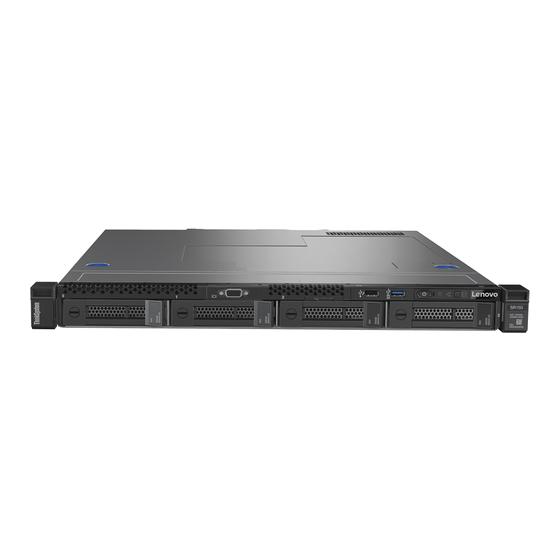
Page 22: Front View
Figure 4. SR150 QR code Front view This section contains information about the controls, LEDs, and connectors on the front of the server. The following illustration shows the controls, LEDs, and connectors on the front of the server. ThinkSystem SR150 Setup Guide... - Page 23 Connect a USB device, such as a USB mouse, keyboard, or other device, to any of these connectors. Following are detailed descriptions of each connector: • USB 1: USB 2.0 with Lenovo XClarity Controller management • USB 2: USB 3.1 Gen1 Front operator panel Front operator panel contains several LED and buttons, see “Front operator panel”...
-
Page 24: Front Operator Panel
Identification button/LED (blue) Use this blue LED to visually locate the server among other servers. This LED is also used as a presence detection button. You can use Lenovo XClarity Administrator to light this LED remotely. System error LED (yellow) When this yellow LED is lit, it indicates that a system error has occurred. - Page 25 • Ethernet connector 2: connect server to the internet • Ethernet connector 1: connect server to the internet, or set server to access Lenovo XClarity Controller If the LOM adapter is not installed, Ethernet connector 1 can be set as XClarity Controller Network connector.
-
Page 26: System-Board Layout
Serial connector: Connect a 9-pin serial device to this connector. The serial port is shared with the Lenovo XClarity Controller. The Lenovo XClarity Controller can take control of the shared serial port to redirect serial traffic, using Serial over LAN (SOL). - Page 27 Chapter 2 Server components...
- Page 28 Figure 9. System-board connectors Table 6. System board connectors USB connector System power connector LAN 2 connector Fan 3 connector LAN 1 connector (shared with Lenovo XClarity TPM card connector Controller) Serial port connector (upper) and VGA connector M.2 connector (bottom)
-
Page 29: System-Board Jumpers And Buttons
Jumper setting / button function Force XCC update jumper • Pins 1 and 2: Default • Pins 2 and 3: Force the Lenovo XClarity Controller to update to the latest version NMI button Press this button to force a nonmaskable interrupt (NMI) to the processor. -
Page 30: Pcie Riser Assembly
Use this information to locate the connectors on the optional PCIe riser assembly. Figure 11. PCIe riser assembly Table 8. PCIe riser assembly PCI Express 3.0 x8 PCI Express 3.0 x8 (x16 mechanical connector with x8 signal) Backplate Use this information to identify the drive backplate you use. ThinkSystem SR150 Setup Guide... -
Page 31: Internal Cable Routing
Two 3.5-inch drive backplate Figure 12. Two 3.5-inch drive backplate Four 3.5-inch drive backplate (connects to onboard SATA connectors) Figure 13. Four 3.5-inch drive backplate (connects to onboard SATA connectors) Four 3.5-inch drive backplate (connects to RAID adapter) Figure 14. Four 3.5-inch drive backplate (connects to RAID adapter) Internal cable routing Some of the components in the server have internal cables and cable connectors. - Page 32 Fan cables Connect the fan cables to the corresponding connectors. Make sure all cables are connected for proper fan operation. Figure 15. Fan cables ThinkSystem SR150 Setup Guide...
-
Page 33: Vga Cable
VGA cable Connect the VGA cable to the VGA connector. VGA cable Connect the VGA cable to the connector and route the cable as shown. Figure 16. VGA cable Chapter 2 Server components... -
Page 34: Fixed Power Supply Cables
Fixed power supply unit cables Connect the cables to the corresponding connectors and route the cables as shown. Figure 17. Fixed power supply unit cables Table 9. Processor and system power connector Processor power connector System-board power connector ThinkSystem SR150 Setup Guide... -
Page 35: Backplate Cables
Backplate cables Connect drive backplate cables to the corresponding connectors. Check “System-board connectors” on page 18 for the detailed connectors location. Two 3.5-inch drive backplate Figure 18. Two 3.5-inch drive backplate Table 10. Two 3.5-inch drive backplate Backplate power connector Chapter 2 Server components... - Page 36 Four 3.5-inch drive backplate (connects to onboard connectors) Figure 19. Four 3.5-inch drive backplate (connects to onboard connectors) Table 11. Four 3.5-inch drive backplate (connects to onboard connectors) Backplate power connector ThinkSystem SR150 Setup Guide...
-
Page 37: Parts List
Use the parts list to identify each of the components that are available for your server. For more information about ordering the parts shown in Figure 21 “Server components” on page 30: https://datacentersupport.lenovo.com/products/servers/thinksystem/se350/parts Note: Depending on the model, your server might look slightly different from the illustration. - Page 38 Tier 1 CRU at your request with no service agreement, you will be charged for the installation. • Tier 2 customer replaceable unit: You may install a Tier 2 CRU yourself or request Lenovo to install it, at no additional charge, under the type of warranty service that is designated for your server.
- Page 39 • Consumable and Structural parts: Purchase and replacement of consumable and structural parts (components, such as a cover or bezel) is your responsibility. If Lenovo acquires or installs a structural component at your request, you will be charged for the service.
- Page 40 ThinkSystem SR150 Setup Guide...
-
Page 41: Chapter 3. Server Hardware Setup
Validate that the server hardware was set up successfully. See “Validate server setup” on page 59. 3. Configure the system. a. Connect the Lenovo XClarity Controller to the management network. See “Set the network connection for the Lenovo XClarity Controller” on page 61. -
Page 42: Installation Guidelines
• When you install a new server, download and apply the latest firmware. This will help ensure that any known issues are addressed, and that your server is ready to work with optimal performance. Go to ThinkSystem SR150 Drivers and Software to download firmware updates for your server. -
Page 43: System Reliability Guidelines
System reliability guidelines Review the system reliability guidelines to ensure proper system cooling and reliability. Make sure the following requirements are met: • When the server comes with redundant power, a power supply must be installed in each power-supply bay. •... -
Page 44: Remove The Security Bezel
Use the key to unlock the security bezel to the open position. Figure 22. Unlocking the security bezel Step 2. Press the release latch and rotate the security bezel outward to remove it from the chassis. Figure 23. Security bezel removal ThinkSystem SR150 Setup Guide... -
Page 45: Remove The Top Cover
Table 14. Security bezel removal Release latch If you are instructed to return the component or optional device, follow all packaging instructions, and use any packaging materials for shipping that are supplied to you. Remove the top cover Use this information to remove the top cover. To avoid possible danger, read and follow the following safety information. -
Page 46: Remove The Air Baffle
3. If server is installed in a rack, remove the server from the rack. 4. Remove the top cover (see “Remove the top cover” on page 37). To remove the air baffle, complete the following steps: Figure 25. Air baffle removal ThinkSystem SR150 Setup Guide... -
Page 47: Install A Fan
Step 1. Lift the air baffle up and set it aside. Attention: For proper cooling and airflow, reinstall the air baffle before you turn on the server. Operating the server with the air baffle removed might damage server components. If you are instructed to return the component or optional device, follow all packaging instructions, and use any packaging materials for shipping that are supplied to you. -
Page 48: Install The Simple-Swap Drive Backplate
To install the simple-swap drive backplate, complete the following steps: Notes: There are three types of backplate supported by the server, all are removed and installed in a similar method. • Two 3.5-inch drive backplate • Four 3.5-inch drive backplate (connects to onboard connectors) ThinkSystem SR150 Setup Guide... -
Page 49: Install An Adapter
Notes: • ThinkSystem SR150 does not support ARI/SR-IOV • QLogic QL41262 PCIe 25Gb 2-Port SFP28 Ethernet Adapter does not support shared storage V3700v2 and V5030 configurations. -
Page 50: Install The Flash Power Module
The device also might have more than one power cord. To remove all electrical current from the device, ensure that all power cords are disconnected from the power source. ThinkSystem SR150 Setup Guide... -
Page 51: Install The Pcie Riser Assembly
S004 CAUTION: When replacing the lithium battery, use only Lenovo specified part number or an equivalent type battery recommended by the manufacturer. If your system has a module containing a lithium battery, replace it only with the same module type made by the same manufacturer. The battery contains lithium and can explode if not properly used, handled, or disposed of. - Page 52 Align the two tabs on PCIe riser assembly with the slots on the rear chassis; then, insert the PCIe riser assembly into the connector on the system board. Carefully press the riser card straight down into the slot until it is fully seated. ThinkSystem SR150 Setup Guide...
-
Page 53: Install The M.2 Drive
Figure 32. PCIe riser assembly installation After you install the PCIe riser assembly, complete the following steps: 1. Install the top cover onto the server (see “Install the top cover” on page 56). 2. Install the server into the rack if necessary. 3. - Page 54 Note: When you install the 80 mm or the 42 mm M.2 drive, you need to change the hex screw location accordingly as the following illustration. Figure 34. Hex screw location for 80 mm/42 mm M.2 drive ThinkSystem SR150 Setup Guide...
-
Page 55: Install The Cmos Battery (Cr2032)
To install the M.2 drive, complete the following steps: Note: When the fourth SATA drive is installed, the M.2 drive is not supported. Figure 35. M.2 drive installation Step 1. Insert the M.2 drive at an angle to the connector as shown. Step 2. - Page 56 CAUTION: When replacing the lithium battery, use only Lenovo specified part number or an equivalent type battery recommended by the manufacturer. If your system has a module containing a lithium battery, replace it only with the same module type made by the same manufacturer. The battery contains lithium and can explode if not properly used, handled, or disposed of.
-
Page 57: Install The Fixed Power Supply Unit
After you install the CMOS battery, complete the following steps: 1. Install the top cover onto the server (see “Install the top cover” on page 56). 2. Install the server into the rack if necessary. 3. Reconnect power cords and all external cables. Install the fixed power supply unit Use this information to install the fixed power supply unit. -
Page 58: Install A Dimm
Before you install a DIMM, complete the following steps: 1. Read “Safety” on page iii and “Installation Guidelines” on page 34 to ensure that you work safely. 2. Remove the air baffle if necessary (see “Remove the air baffle” on page 38). ThinkSystem SR150 Setup Guide... - Page 59 3. Touch the static-protective package that contains the component to any unpainted metal surface on the server; then, remove it from the package and place it on a static-protective surface. The following illustration shows the system-board components, including DIMM connectors. Figure 38.
-
Page 60: Install The Processor
Note: If you are applying new thermal grease on the top of the processor, make sure to do it after the alcohol has fully evaporated. 3. Apply the thermal grease on the top of the processor with syringe by forming four uniformly spaced dots, while each dot consists of about 0.1 ml of thermal grease. ThinkSystem SR150 Setup Guide... - Page 61 Figure 40. Proper shape of the thermal grease 4. Touch the static-protective package that contains the component to any unpainted metal surface on the server; then, remove it from the package and place it on a static-protective surface. To install the processor, complete the following steps: Step 1.
-
Page 62: Install The Heat Sink
1. Read “Safety” on page iii and “Installation Guidelines” on page 34 to ensure that you work safely. To install the heat sink, complete the following steps: Step 1. Align the four screws on the heat sink with the corresponding screw holes on the system board. ThinkSystem SR150 Setup Guide... -
Page 63: Install The Air Baffle
Step 2. Tighten screw 1 and 2: Partially tighten screw 1. Fully tighten screw 2. Fully tighten screw 1. Figure 43. Heat sink installation Step 3. Tighten screw 3 and 4: Partially tighten screw 3. Fully tighten screw 4. Fully tighten screw 3. After you install the heat sink, complete the following steps: 1. -
Page 64: Install The Top Cover
S033 CAUTION: Hazardous energy present. Voltages with hazardous energy might cause heating when shorted with metal, which might result in spattered metal, burns, or both. ThinkSystem SR150 Setup Guide... -
Page 65: Install A Simple-Swap Disk Drive
Before you install the top cover, complete the following steps: 1. Read “Safety” on page iii and “Installation Guidelines” on page 34 to ensure that you work safely. 2. Make sure all the removed components are installed, and all the disconnected cables inside the server are reconnected. -
Page 66: Install The Server In A Rack
After the server performs a short self-test (power status LED flashes quickly) when connected to input power, it enters a standby state (power status LED flashes once per second). The server can be turned on (power LED on) in any of the following ways: ThinkSystem SR150 Setup Guide... -
Page 67: Validate Server Setup
Power off the server The server remains in a standby state when it is connected to a power source, allowing the Lenovo XClarity Controller to respond to remote power-on requests. To remove all power from the server (power status LED off), you must disconnect all power cables. - Page 68 ThinkSystem SR150 Setup Guide...
-
Page 69: Chapter 4. System Configuration
The following methods are available to set the network connection for the Lenovo XClarity Controller if you are not using DHCP: • If a monitor is attached to the server, you can use Lenovo XClarity Controller to set the network connection. -
Page 70: Update The Firmware
Machine-type-specific firmware-only UXSPs are also available. See the following table to determine the best Lenovo tool to use for installing and setting up the firmware: Note: The server UEFI settings for option ROM must be set to Auto or UEFI to update firmware using Lenovo XClarity Administrator or Lenovo XClarity Essentials. - Page 71 The latest firmware can be found at the following site: https://datacentersupport.lenovo.com/products/servers/thinksystem/se350/downloads • Lenovo XClarity Provisioning Manager From Lenovo XClarity Provisioning Manager, you can update the Lenovo XClarity Controller firmware, the UEFI firmware, and the Lenovo XClarity Provisioning Manager software. Chapter 4...
- Page 72 Additional information about using Lenovo XClarity Provisioning Manager to update firmware is available http://sysmgt.lenovofiles.com/help/topic/LXPM/platform_update.html • Lenovo XClarity Controller If you need to install a specific update, you can use the Lenovo XClarity Controller interface for a specific server. Notes: – To perform an in-band update through Windows or Linux, the operating system driver must be installed and the Ethernet-over-USB (sometimes called LAN over USB) interface must be enabled.
-
Page 73: Configure The Firmware
Several options are available to install and set up the firmware for the server. Important: Do not configure option ROMs to be set to Legacy unless directed to do so by Lenovo Support. This setting prevents UEFI drivers for the slot devices from loading, which can cause negative side effects for Lenovo software, such as Lenovo XClarity Administrator and Lenovo XClarity Essentials OneCLI, and to the Lenovo XClarity Controller. -
Page 74: Memory Configuration
Several options are available to install an operating system on the server. • Lenovo XClarity Administrator If you are managing your server using Lenovo XClarity Administrator, you can use it to deploy operating- system images to up to 28 managed servers concurrently. For more information about using Lenovo XClarity Administrator to deploy operating system images, see: http://sysmgt.lenovofiles.com/help/topic/com.lenovo.lxca.doc/compute_node_image_deployment.html... -
Page 75: Back Up The Server Configuration
Alternatively, you can use the s s a a v v e e command from Lenovo XClarity Essentials OneCLI to create a backup of all configuration settings. For more information about the s s a a v v e e command, see: http://sysmgt.lenovofiles.com/help/topic/toolsctr_cli_lenovo/onecli_r_save_command.html... - Page 76 ThinkSystem SR150 Setup Guide...
-
Page 77: Chapter 5. Resolving Installation Issues
• “Server cannot recognize a hard drive” on page 70 • “Displayed system memory less than installed physical memory” on page 71 • “A Lenovo optional device that was just installed does not work.” on page 71 Server does not power on Complete the following steps until the problem is resolved: 1. - Page 78 • Replace the affected backplane signal cable. • Replace the affected backplane. 8. Run the diagnostics tests for the hard disk drives. When you start a server and press F1, the Lenovo XClarity Provisioning Manager interface is displayed by default. You can perform hard drive diagnostics from this interface.
- Page 79 • There is no memory mismatch when the server is at the minimum memory configuration. 2. Reseat the DIMMs, and then restart the server. 3. Run memory diagnostics. When you start a server and press F1, the Lenovo XClarity Provisioning Manager interface is displayed by default. You can perform memory diagnostics from this interface.
- Page 80 ThinkSystem SR150 Setup Guide...
-
Page 81: Appendix A. Getting Help And Technical Assistance
Appendix A. Getting help and technical assistance If you need help, service, or technical assistance or just want more information about Lenovo products, you will find a wide variety of sources available from Lenovo to assist you. On the World Wide Web, up-to-date information about Lenovo systems, optional devices, services, and support are available at: http://datacentersupport.lenovo.com... -
Page 82: Collecting Service Data
Collecting service data To clearly identify the root cause of a server issue or at the request of Lenovo Support, you might need collect service data that can be used for further analysis. Service data includes information such as event logs and hardware inventory. -
Page 83: Contacting Support
• Lenovo XClarity Essentials OneCLI Lenovo XClarity Essentials OneCLI has inventory application to collect service data. It can run both in- band and out-of-band. When running in-band within the host operating system on the server, OneCLI can collect information about the operating system, such as the operating system event log, in addition to the hardware service data. - Page 84 ThinkSystem SR150 Setup Guide...
-
Page 85: Index
CMOS battery (CR2032) handling static-sensitive devices collecting service data hard disk drive activity LED Common installation issues hard disk drive status LED Configuration - ThinkSystem SR150 hardware options configure the firmware installing connector hardware service and support telephone numbers HDD backplane connector... - Page 86 LED front Identification LED, front System information LED system board connectors operator information panel release latch System configuration - ThinkSystem SR150 system reliability guidelines System-board jumpers System-board layout System-board LEDs parts list PCIe riser assembly connectors installing...
- Page 88 Part Number: SP47A31795 Printed in Chinese Mainland (1P) P/N: SP47A31795 *1PSP47A31795*...