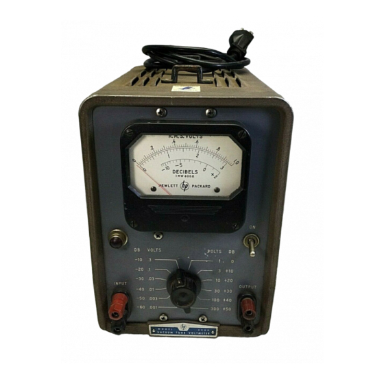
HP 400D Service Note
Vacuum tube voltmeter
Hide thumbs
Also See for 400D:
- Organizational, ds, gs, and depot maintenance manual (73 pages) ,
- Operating and servicing manual (50 pages) ,
- Operating and service manual (30 pages)
Advertisement
Quick Links
@
MODELS 400D, 400H, AND 400L
VACUUM TUBE VOLTMETERS
TEST, ADJUSTMENT, AND CERTIFICATTON METHODS
These Service Notes have been prepared as an aid in
testing and adjusting all
@
Model 400D, 400H, and
400L Vacuum Tube Voltmeters. The procedures that
follow supersede those in other Service Notes o r Op-
erating and Servicing Manuals for these instruments.
All circuit references apply to one of the three ref-
erence schematic diagrams in these Service Notes.
No attempt should be made to make an instrument
agree completely
with
any one of these schematics.
All recommended circuit changes a r e described in
Section I of these Service Notes.
Voltages mentioned herein a r e measured between
the indicated points and the chassis unless specified
otherwise.
The voltmeter power supply should al-
ways be tested before undertaking repair and adjust-
ment of any other section of the instrument.
These Service Notes a r e divided into five sections
as follows:
Section
Page
I MODIFICATIONS
1
I1 TUBE
&
CRYSTAL DIODE REPLACEMENT
2
111
TEST EQUIPMENT REQUIRED
3
IV TEST & CALIBRATION PROCEDURE
3
A.
Setting Mechanical
in Models 400D
o r 400H
3
B. Setting Mechanical Zero in Model 400L
3
C. Check Regulated Power Supply
4
D. Set dc Heater Voltage
4
E. Input Divider Circuit Identification
4
F. Input Circuit Preliminary Frequency
Response Adjustment
5
G. Basic Calibration (Setting Amplifier Gain)
5
H. Basic Calibration (Setting Input Divider)
5
I. Miscellaneous Checks
5
J.
Recheck dc Heater Voltage
6
K. Check Calibration and Tracking
6
L. Check Effect of Line Voltage Change
6
M. Frequency Response Adjustment
6
V TESTS FOR INSTRUMENT CERTIFICATION 8
N. Final Check and Adjustment
7
S E C T I O N I
-
M O D I F I C A T I O N S
Modifications in certain serials of
( $ 9
Model 400D,
400H, and 400L Voltmeters can simplify testing. Speci-
fications have not been changed, Modernization of
instruments will simplify repair and testing and will
add to instrument reliability. The changes that follow
apply only to those 400D, 400H, and 400L instruments
having the specified serial numbers.
A.
MODEL 400D SERIAL NO. 2221 AND BELOW
Change V2 plate load resistor R23 from an 8200
ohm, *5%,
1
watt, composition resistor to a metallic
oxide film-type having the same resistance, tolerance,
and wattage rating. This Corning Glass Works style
N25 resistor is availableunder@ StockNo. 0761-0001.
This change is particularly recommended for those
instruments in which the residual noise reading is too
high and/or unstable.
Mount the new resistor as
nearly
as
possible in the same location a s the old
resistor.
' b
distribution abcfg
B. MODEL 400D SERIAL NO, 3944 AND BELOW
Add resistor R67 in series with the control grid
of the series regulator tube V7. Transfer
the
wire
(usually green) from V7 pin 1 to vacant pin 6 on the
same tube socket. Connect a 470 ohm
f
lo%, 1/2 watt
composition resistor
(@
Stock No. 0687-471 1) between
V7 socket pins
1
and 6.
This resistor prevents parasitic oscillation in the
power supply. Such oscillation can cause the meter
to be deflected
full
scale against the right hand stop.
C. MODEL 400D SERIAL NO.
4344
AND BELOW
I
Add 10 ohm *lo%
1
watt, composition resistor
(@
Stock No. 0690-1001) R68 in parallel with heater
voltage adjustment control R66. This resistor reduces
power dissipation in R66 and extends the life of the
control.
Readjust the dc heater voltage after in-
stalling R68.
00665-4
COMPLETE COJERAGE IN
H
E
T - P A C K A R D
C
R U E
D U
V f t
Q I N C V A ,
W L I I "WCWIACN
LLECTRONK
MEASURING
kQUIPMENT
I 5 0 8
+
A 4
8
Y
I
L
L
R
o
A
D
F A L O A b T O p C A L I I O R W I A , 1 . 5 . A .
C A I L I : "UlW;*CW*
U Y ~ W O R T
* - I 0 0 0
r ( M c . 0
*db..,A.
E*
Advertisement


