Advertisement
Quick Links
s
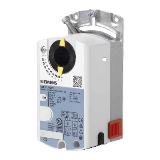
OpenAir™
VAV compact controller Modbus RTU
G..B181.1E/MO
A6V10631832_en--_b
2016-01-29
VAV compact controllers 5 / 10 Nm with Modbus communication
GDB181.1E/MO
GLB181.1E/MO
Operating voltage AC 24 V, 5 Nm
Operating voltage AC 24 V, 10 Nm
Siemens
Building Technologies
Advertisement

Related Manuals for Siemens OpenAir


Summary of Contents for Siemens OpenAir
- Page 1 OpenAir™ VAV compact controller Modbus RTU G..B181.1E/MO VAV compact controllers 5 / 10 Nm with Modbus communication GDB181.1E/MO Operating voltage AC 24 V, 5 Nm GLB181.1E/MO Operating voltage AC 24 V, 10 Nm A6V10631832_en--_b Siemens 2016-01-29 Building Technologies...
- Page 2 VAV control core parameters are therefore protected against unauthorized changes after production. For configuration and maintenance the service tools AST20 (handheld tool) or ACS931 / ACS941 (PC tool, to be used with AST11) are available. 2 / 14 Siemens A6V10631832_en--_b Building Technologies 2016-01-29...
- Page 3 Mounting / installation instruction A6V10523083 Modbus / BACnet Related documents such as environmental declarations, CE declarations, etc., can be down- loaded at the following Internet address: http://siemens.com/bt/download Notes Safety Caution National safety regulations Failure to comply with national safety regulations may result in personal injury and property damage.
- Page 4 “Settings and operating mode” to the OEM default values. Since these values can be set by the OEM, they are not necessarily the same as the Siemens factory settings. All other parameters, especially the bus parameters, are reset to Siemens factory settings.
- Page 5 1. Enter addressing mode 2. Set 1-digits: Press button 5-times LED flashes per button press green 3. Store address: press button until LED shines address is stored and displayed 1x for confirmation 5 / 14 A6V10631832_en--_b Siemens 2016-01-29 Building Technologies...
- Page 6 A constant air volume flow can be achieved by sending a constant setpoint value. Position control The VAV compact controllers can be operated as damper actuators, i.e. using the 0..100% setpoint as position damper setpoint, by setting the operating mode parameter to “POS”. 6 / 14 Siemens A6V10631832_en--_b Building Technologies 2016-01-29...
- Page 7 New value (ex.) MacAddress Baudrate 0 = auto 1 = 9600 Transmission Mode 0 = 1-8-E-1 3 = 1-8-N-2 Termination 0 = Off 0 = Off BusConfigCmd 0 = Ready 1 = Load 7 / 14 A6V10631832_en--_b Siemens 2016-01-29 Building Technologies...
- Page 8 Comply with all local and currently applicable laws and regulations. Warranty Technical data on specific applications are valid only together with Siemens products listed under "Equipment combinations". Siemens rejects any and all warranties in the event that third-party products are used.
-
Page 9: Technical Data
Default: Auto Termination electronically switchable Default: Off Degree of protection Degree of protection Degree of protection acc. to EN 60529 IP54 (see mounting instruction) Safety class Safety class acc. to EN 60730 9 / 14 A6V10631832_en--_b Siemens 2016-01-29 Building Technologies... - Page 10 ± 4.5 % of the measured value Amplitude mounting position ± 0.1 Pa / Year Drift 3000 Pa Max. permissible operating pressure 3000 Pa Max. permissible overload on one side The documents can be downloaded from http://siemens.com/bt/download 10 / 14 Siemens A6V10631832_en--_b Building Technologies 2016-01-29...
-
Page 11: Modbus Registers
0 = Ready / 1 = Load / 2 = Discard Status See below Device information 1281 Factory Index 1282-83 Factory Date Cf. product documentation A6V10631862 1284-85 Factory SeqNo 1409-16 TypeASN [Char_16..1] 11 / 14 A6V10631832_en--_b Siemens 2016-01-29 Building Technologies... - Page 12 The operating voltage at terminals G and G0 must comply with the requirements under SELV or PELV. Safety transformers with twofold insulation as per EN 61558 required; they must be designed to be on 100 % of the time. 12 / 14 Siemens A6V10631832_en--_b Building Technologies 2016-01-29...
- Page 13 Dimensions G..B181.1E/.. min. 100 3547M01 Ø 3...8 8 - 16 mm 12.8 mm min. 80 15 mm Measurements in mm 13 / 14 A6V10631832_en--_b Siemens 2016-01-29 Building Technologies...
- Page 14 Issued by © Siemens Switzerland Ltd, 2015 Technical specifications and availability subject to change without notice. Siemens Switzerland Ltd Building Technologies Division International Headquarters Gubelstrasse 22 6301 Zug Switzerland Tel. +41 41-724 24 24 www.siemens.com/buildingtechnologies Document ID A6V10631832_en--_b Issue 2016-01-29...