Advertisement
Advertisement
Table of Contents

Related Manuals for Dell EMC VNXe Series


Summary of Contents for Dell EMC VNXe Series
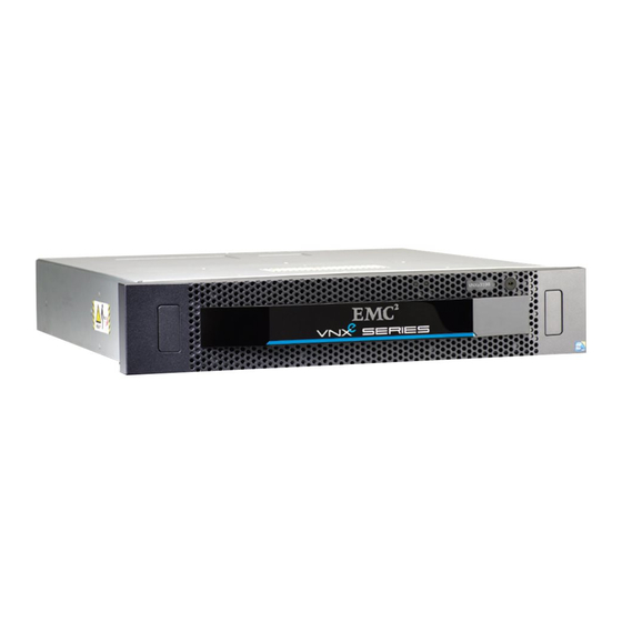
- Page 1 VNXe Series ® ™ VNXe3100 ™ Hardware Information Guide P/N 300-012-289 REV 03...
- Page 2 Copyright © 2012 EMC Corporation. All rights reserved. Published in the USA. Published June, 2012 EMC believes the information in this publication is accurate as of its publication date. The information is subject to change without notice. The information in this publication is provided as is. EMC Corporation makes no representations or warranties of any kind with respect to the information in this publication, and specifically disclaims implied warranties of merchantability or fitness for a particular purpose.
-
Page 3: Table Of Contents
CONTENTS Preface Chapter 1 Overview VNXe3100 platform..................11 Front view ..................... 12 Rear view ....................12 Hardware features................. 13 System component description ..............14 Disk processor enclosure ..............14 Front view ..................... 16 Rear view ....................17 Cache Protection Module ..............35 Disk-array enclosure ................ - Page 4 Contents EMC VNXe3100 Hardware Information Guide...
- Page 5 Preface As part of an effort to improve its product lines, EMC periodically releases revisions of its software and hardware. Therefore, some functions described in this document might not be supported by all versions of the software or hardware currently in use. The product release notes provide the most up-to-date information on product features.
- Page 6 Preface IMPORTANT In a dual SP system, when calculating the number of drives for your VNXe3100 platform, the DPE is included in the total drive slot quantity of from 96 to 99 drives in a dual SP system. If the total drive slot quantity exceeds from 96 to 99, you will not be able to add another DAE.
-
Page 7: Preface
Preface How this document is organized The major sections of this guide are listed in the following table. Title Description “Overview” on page 11 Describes the software and hardware features of a typical VNXe3100 along with a front view example of the VNXe3100. “VNXe3100 platform”... - Page 8 Preface Conventions used in this document EMC uses the following conventions for special notices: DANGER indicates a hazardous situation which, if not avoided, will result in death or serious injury. WARNING indicates a hazardous situation which, if not avoided, could result in death or serious injury.
- Page 9 Preface Used for: Courier • System output, such as an error message or script • URLs, complete paths, filenames, prompts, and syntax when shown outside of running text Used for: Courier bold • Specific user input (such as commands) Used in procedures for: Courier italic •...
- Page 10 Preface EMC VNXe3100 Hardware Information Guide...
-
Page 11: Vnxe3100 Platform
Overview The VNXe Series provides an integrated storage platform for small and medium businesses as well as remote offices and departments in larger enterprise businesses. Providing significant advancements in efficiency and simplicity, the VNXe Series facilitates complete storage consolidation with advanced file and block functionality as well as a simple, application-driven approach to managing shared storage. -
Page 12: Front View
Overview Note: A fully configured dual SP VNXe3100 platform includes up to seven DAEs supporting a maximum of from 96 to 99 disk drives depending on the type and mix of the DAEs used (for configuration information, see “DPE and DAE configuration rules” on page 37). -
Page 13: Hardware Features
Overview Hardware features Contained in a 2U platform architecture, the VNXe3100 platform weighs approximately 60.5 lb (26.4 kg). It measures 3.5 inches high x 17.5 inches wide x 19.75 inches deep (8.89 cm x 44.45 cm x 50.16 cm). Between the front and rear of the enclosure, a midplane distributes power and signals to all the enclosure components. -
Page 14: System Component Description
Overview – One 10/100/1000 LAN service (RJ-45) port (not used) – One USB port (not used) – One power supply module Either a 2U, 12 (3.5-inch) disk drive DAE or a 2U, 25 (2.5-inch) disk drive DAE is ◆ supported in several configurations (for more DPE/DAE configuration information, see Table 16 on page 37 Table 17 on page Note: The 2U 25, (2.5-inch) disk drive DAE is only supported when you have VNXe... - Page 15 Overview Midplane ◆ Storage processor (SP) ◆ Power supply module ◆ Cache Protection Module (single SP configuration only) ◆ EMI shielding ◆ Drive carrier Disk drive carriers are plastic assemblies that provide smooth, reliable contact with the enclosure slot guides and midplane connectors. Each carrier has a handle with a latch and spring clips.
-
Page 16: Front View
Overview In the event of a power failure, the backup battery in the Cache Protection Module provides the power necessary to write the entire contents of the mirrored cache memory to non-volatile storage or Flash memory in the Cache Protection Module. The “Cache Protection Module”... -
Page 17: Rear View
Overview Table 1 describes the VNXe3100 platform 2U DPE and the disk drive status LEDs. Table 1 VNXe3100 platform 2U, 12 (3.5-inch) DPE and disk drive LEDs Color State Description DPE power (location 2) Blue Powering and powered up — Powered down Disk drive ready/activity Blue... - Page 18 Overview Figure 6 shows an example of the rear view of a 2U DPE with a Cache Protection Module and a single storage processor (SP A), respectively. e0 e1 1 GBE 6Gb SAS 6Gb SAS VNX-000086 SP (for a closer view, see Figure 8 on page Power supply module (for a closer view,...
- Page 19 Overview Viewing from the rear of the DPE, each SP (B and A), respectively, consists of connectors, status LEDs, latch handles, and so on. AC power supply module: ◆ • Power in (recessed) connector (plug) • Power supply status LEDs (power on and fault) •...
- Page 20 Overview e0 e1 1 GBE 6Gb SAS 6Gb SAS VNX-000082 AC power in connector (recessed plug) SP unsafe to remove LED (white) RS-232/EIA (micro DB-9) connector SP power LED (green) (labeled with a wrench symbol) Power supply module SP status/fault LED (amber/blue Power supply latch handle (top, middle) 1.
- Page 21 Overview AC power supply/cooling module Figure 9 on page 21 shows an example of the AC power supply module with a power in (recessed) connector (plug) and status LEDs. The SP is cooled by this power supply located on the top portion of the 2U DPE. The power supply/cooling module has a separate latch handle located on the top, middle portion of the module.
- Page 22 Overview • Four-port 1-Gb/s copper Ethernet I/O personality module • Two (RJ-45) LAN connectors (labeled with a network management symbol and a wrench symbol) Note: The RJ-45 LAN connector with a wrench symbol is not used at this time. • Two (micro DB-9) RS-232/EIA connectors (labeled with a battery symbol and a wrench symbol) Note: The DB-9 connector with a battery symbol is not used at this time.
- Page 23 Overview e0 e1 1 GBE 6Gb SAS 6Gb SAS VNX-000099 RS-232/EIA (micro DB-9) connector CRU fault LED (amber (labeled with a wrench symbol) Management LAN (RJ-45) port (labeled SP unsafe to remove LED (white) with a network management symbol) Service LAN (RJ-45) port (labeled with a SP power LED (green) wrench symbol);...
- Page 24 Overview Table 3 describes the SP status LEDs. The locations in Table 3 are shown in Figure 10 on page Table 3 SP LEDs Color State Description CRU fault Amber Fault, lights amber when an internal customer (location 7) replaceable unit (CRU) has faulted. —...
- Page 25 Overview Table 3 SP LEDs (continued) Color State Description Status/fault — Ready for I/O (location 10) Blue with blinking amber System not initialized. No management IP address once every three seconds is assigned. Note: When the SP Fault/status LED starts blinking four times a second and the SP does not appear to be functioning, a cache-dirty condition has occurred.
- Page 26 Overview 6-Gb/s SAS ports — The VNXe3100 platform SP has two 6-Gb/s SAS ports (labeled 6GB SAS 0 x4 and 6GB SAS 1 x4) on the rear of each SP (A and B). These ports provide an interface for SAS and NL-SAS drives on the DAE. This port is a 26-circuit SAS small form-factor 8088 (SFF-8088) specification connector (socket or receptacle) using an SFF-8088 specification mini-SAS 26-circuit cable (plug) with a pull tab.
- Page 27 Overview SP 6-Gb/s SAS port LEDs — Figure 12 shows an example of the SP 6-Gb/s SAS ports (labeled 6-Gb SAS 0 x4 and 1 x4) LEDs (blue) below the bottom connector. These LEDs indicate the link/activity of the 0 x4 and 1 x4 6-Gb/s SAS ports. Note: The 6GB SAS port 1 x4 is not used at this time.
- Page 28 Overview Personality card fault LED e0 e1 VNX-000092 Link LED Activity LED Figure 13 1-Gb/s copper Ethernet I/O personality module (RJ-45) port LEDs Table 6 describes the SP optional 1-Gb/s copper Ethernet I/O personality module (RJ-45) fault and port LEDs. Table 6 1-Gb/s copper Ethernet I/O personality module (RJ-45) fault and port LEDs Color State...
- Page 29 Overview The two-port 10-Gb/s copper Ethernet (RJ-45) ports on the two-port 10-Gb/s copper Ethernet I/O personality module are LAN ports not WAN ports. LAN ports contain safety extra-low voltage (SELV) circuits, and WAN ports contain telephone-network voltage (TNV) circuits. Some LAN and WAN ports both use RJ-45 connectors. Use caution when connecting cables.
- Page 30 Overview Two 1-Gb/s iSCSI host IP connect (RJ-45) ports IMPORTANT The ports shown in Figure 15 are 1-Gb/s iSCSI ports. A symbol depicting a telephone handset with a line through it indicates that you should not connect WAN type RJ-45 telephone connectors to these ports.
- Page 31 Overview Table 9 1-Gb/s iSCSI host IP connect (RJ-45) port LEDs (continued) Color State Description Right, link Green 100-Mb/s connection speed Amber 1000-Mb/s (or 1-Gb/s) connection (location 2) — 10-Mb/s connection (if left LED is on or blinking) Network management and service laptop Ethernet (RJ-45) ports The SP Ethernet (RJ-45) ports are LAN ports not WAN ports.
- Page 32 Overview To access the Ethernet ports, connect a Category 3, 4, 5, 5E, or 6 unshielded twisted-pair (UTP) cable to the RJ-45 connectors on the back of the SP, as described in Table Table 10 Ethernet cabling guidelines Type Description 10Base-T EIA Categories 3, 4, or 5 UTP (2 or 4 pairs) up to 328 ft (100 m) 100Base-TX...
- Page 33 Overview Network management and service laptop Ethernet (RJ-45) port LEDs — Figure 19 shows the SP network management and service laptop Ethernet (RJ-45) port LEDs—a green LED to the left of the connector and a bi-color (green/amber) LED to the right of the connector—that indicate the link/activity and speed of the Ethernet ports, respectively.
- Page 34 Overview Table 13 lists the SP serial RS-232/EIA 232 (micro DB-9) pin signals used on the connector. Table 13 Serial RS-232/EIA 232 (micro DB-9) connector (socket) pinout DB-9 Pin Signal Description Carrier detect Received data Transmitted data Data terminal ready Ground Data set ready Request to send...
-
Page 35: Cache Protection Module
Overview Table 14 lists the SP serial RS-232/EIA 232 (micro DB-9) pin signals used on the connector. Table 14 Serial RS-232/EIA 232 (micro DB-9) connector (socket) pinout DB-9 Pin Signal Description Carrier detect Received data Transmitted data Data terminal ready Ground Data set ready Clear to send... -
Page 36: Disk-Array Enclosure
Overview Table 15 lists the Cache Protection Module LEDs. Table 15 Cache Protection Module status LEDs Color State Description Power Green Power on — Power off Fault Amber Fault — No fault Do not Unsafe to White remove; data could be lost remove —... - Page 37 Overview IMPORTANT When calculating the number of drives for your VNXe3100 platform, the 2U DPE is included in the total drive slot quantity of from 96 to 99 drives in a dual SP system. If the total drive slot quantity exceeds from 96 to 99, you will not be able to add another DAE. When calculating the number of drives for your VNXe3100 platform, the 2U DPE is included in the total drive slot quantity of from 48 to 49 drives in a single SP system.
- Page 38 Overview DAE description Each DAE consists of the following components: Drive carrier ◆ Disk drives ◆ Midplane ◆ Link control cards (LCCs) ◆ Power supply/cooling modules ◆ EMI shielding ◆ Drive carrier Disk drive carriers are plastic assemblies that provide smooth, reliable contact with the enclosure slot guides and midplane connectors.
- Page 39 Overview Figure 26 on page 42 shows the three status LEDs on the power supply/cooling module. The enclosure cooling system consists of dual-blower modules in each power supply/cooling module. EMI shielding EMI compliance requires a properly installed electromagnetic interference (EMI) shield in front of the DAE disk drives.
- Page 40 Overview Table 18 describes the DAE and the 3.5-inch disk drive status LEDs Table 18 2U, 12 (3.5-inch) DAE and disk drive LEDs Color State Description DAE power (location 2) Blue Powering and powered up — Powered down Disk drive on/activity Blue Powering and powered up (location 3)
- Page 41 Overview Looking from left to right, Figure 25 shows an example of the rear view of a 2U, 12 (3.5-inch) disk drive DAE. LCC B LCC A 6Gb SAS 6Gb SAS 6Gb SAS 6Gb SAS VNX-000091 LCC B AC power supply power in (recessed LCC B fault LED (on, amber) plug) LCC B power supply LED (on, green)
- Page 42 Overview DAE AC power supply/cooling module Figure 26 shows an example of the 2U, 12 (3.5-inch) disk drive DAE AC power supply/cooling module with a power in (recessed) connector (plug) and status LEDs. Fault LED Power supply in Power on LED Fan fault LED VNX-000083 Figure 26 Example of a DAE AC power supply/cooling module power in (recessed) connector (plug)
- Page 43 Overview 6-Gb/s SAS x4 ports — The 2U, DAE LCC supports two 6-Gb/s SAS x4 ports (labeled 6GB SAS x4) on the rear of each LCC (A and B). This port is a 26-circuit SAS small form-factor 8088 (SFF-8088) specification connector (socket or receptacle) using an SFF-8088 specification mini-SAS 26-circuit cable (plug) with a pull tab.
- Page 44 Overview 6-Gb/s SAS port LEDs and port direction (input or output) — Figure 28 shows the LCC 6-Gb/s SAS port LED—a bi-color (blue/green) LED below the connector, either left or right—that indicates the link of the SAS port. Figure 28 also shows a double black circle (or dot) symbol (for input) or a double black diamond...
- Page 45 Overview 2U, 25 (2.5-inch) DAE On the front, the 2U, 25 (2.5-inch) disk drive DAE carrier includes the following hardware components: 2.5-inch 6-Gb/s SAS or 6-Gb/s NL-SAS disk drives (hot-swappable) ◆ Status LEDs ◆ Note: The 2U 25, (2.5-inch) disk drive DAE is only supported when you have VNXe Operating Environment (OE) software version 2.3.x and above installed.
- Page 46 Overview Table 22 Example of a 2U, 25 (2.5-inch) DAE and the disk drive LEDs (continued) Color State Description Disk drive fault (location 4) Amber Fault has occurred — No fault has occurred Disk drive on/activity Blue Powering and powered up (location 5) Blinking Disk drive activity...
- Page 47 Overview Figure 31 shows an example of the rear view of a 2U, 25 (2.5-inch) disk drive DAE. VNX-000280 LLC B power supply LED (on, green) LCC B bus ID LCC B power supply fault LED (on, amber) LCC B power and fault LEDs LCC B AC power supply power in (recessed DAE enclosure ID or address plug)
- Page 48 Overview Table 23 describes the 2U, 25 (2.5-inch) DAE power supply/cooling module LEDs. Table 23 2U, 25 (2.5-inch) DAE AC power supply/cooling module LEDs Color State Description Power fault Amber Fault Blinking During power shutdown and during overvoltage (OVP) and undervoltage protection (UVP) fault —...
- Page 49 Overview Table 24 lists the 2U, DAE 6-Gb/s SAS port pin signals used on the connector. Table 24 6-Gb/s SAS port connector pinout Signal Signal Rx 0+ Tx 0+ Rx 0- Tx 0- Rx 1+ Tx 1+ Rx 1- Tx 1- Rx 2+ Tx 2+ Rx 2-...
- Page 50 Overview Table 25 describes the 2U DAE LCC 6-Gb/s port LEDs. Table 25 6-Gb/s SAS port LEDs Color State Description Link/activity Blue All lanes are running at 6 GB/s Green One or more lanes is not running at full speed or disconnected Alternating Blinking...
- Page 51 Overview LCC enclosure ID (enclosure address) and bus ID On the rear of the LCC (A and B), an LCC enclosure ID indicator is provided. This ID indicator is a seven-segment LED display for displaying decimal numbers. The LCC enclosure ID appears on both LCCs (A and B) which is the same ID number. The enclosure ID is set at installation (Figure 36).
-
Page 52: Specifications
Overview Specifications Table 27 lists the VNXe3100 platform physical specifications, operating environment, and power requirements. Table 27 VNXe3100 platform specifications Parameter Characteristics Dimensions (approximate) Height 28 in. (71.12 cm) or 16 NEMA units (U) total; one disk processor enclosure (DPE, 2U) and seven disk-array enclosures (2U, 12 [3.5-inch] DAE) Width 17.5 in.