
Related Manuals for ABB BSFC-02C


Summary of Contents for ABB BSFC-02C
- Page 1 — ABB INDUSTRIAL DRIVES BSFC-02C and BSFC-12C charging controllers Hardware manual...
- Page 3 BSFC-02C and BSFC-12C charging controllers Hardware manual Table of contents 3. Installation © 2019 ABB Oy. All Rights Reserved. 3AXD50000027498 Rev B EFFECTIVE: 2019-09-27...
-
Page 5: Table Of Contents
Terms and abbreviations ................. 2 Hardware description Contents of this chapter ................Overview ................... Layout ....................Connectors ..................BSFC-02C ..................BSFC-12C ..................LEDs ....................Connections of the DC supply circuit ............BSFC-02C ..................BSFC-12C ..................Inverter power switch-on sequence ............ - Page 6 6 Table of contents Charging circuit 2×R8i ................ 6 Dimension drawings Contents of this chapter ................BSFC-02C and BSFC-12C ..............Further information...
-
Page 7: Introduction To The Manual
Contents of this chapter This chapter gives the basic information on the manual. Applicability This manual is applicable to BSFC-02C and BSFC-12C charging controllers. Safety instructions Obey all safety instructions delivered with the drive. Read the complete safety instructions before you install, commission, use or service the drive. The complete safety instructions... -
Page 8: Related Documents
8 Introduction to the manual Related documents Manual Code General manuals ACS880 multidrive cabinets and modules safety instructions 3AUA0000102301 ACS880 liquid-cooled multidrive cabinets and modules safety instructions 3AXD50000048633 ACS880 multidrive cabinets and modules electrical planning instructions 3AUA0000102324 ACS880 liquid-cooled multidrive cabinets and modules electrical planning instructions 3AXD50000048634 Drive modules cabinet design and construction instructions 3AUA0000107668... -
Page 9: Terms And Abbreviations
Installation frames for ACS880 multidrive modules hardware manual 3AXD50000010531 Manuals and quick guides for I/O extension modules, fieldbus adapters, safety functions modules, etc. www.abb.com/drives/documents for all manuals on the Internet. You can find all documentation related to the multidrive modules on the Internet at https://sites-apps.abb.com/sites/lvacdrivesengineeringsupport/content. -
Page 11: Hardware Description
Hardware description 11 Hardware description Contents of this chapter This chapter shows an overview of the BSFC units and describes the connectors, settings and LEDs. In addition, it contains circuit diagram examples of the DC supply circuit of ACS880 frame R8i modules, and describes switch-on and switch-off sequences of the units. Overview ACS880 frame size R8i inverter modules can be connected to the drive DC bus through a disconnector (or fuse-switch). -
Page 12: Layout
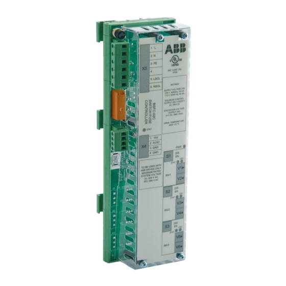
12 Hardware description Layout BSFC-02C BSFC-12C Switch status monitoring (Q10 and Q11). Power supply input for BSFC and operating voltage output for DC switch-disconnector locking solenoid. V1…V6 Fiber optic links to inverters 1, 2 and 3. S1…S3 Enable switches for charging circuit monitoring (inverters 1, 2 and 3). -
Page 13: Connectors
Hardware description 13 Connectors ■ BSFC-02C Connector Description Switch status monitoring (inverter DC switch-disconnector (Q11), and inverter charging switch (Q10)). +15 V Supply voltage for switch status monitoring circuit (Q10 and Q11). Max. 10 mA AUX2 Digital input monitoring the switch status (Q10 and Q11). -
Page 14: Bsfc-12C
14 Hardware description ■ BSFC-12C Connector Description Switch status monitoring (DC switch-disconnector (Q11), and inverter charging switch (Q10)). +24 V Supply voltage for switch status monitoring circuit (Q10 and Q11). Max. 10 mA AUX2 Digital input monitoring the switch status (Q10 and Q11). Ground for control electronics Ground for control electronics Power supply input &... -
Page 15: Connections Of The Dc Supply Circuit
R8i module 1 ;I1V50 INV 1 STAT STAT INV 2 STAT STAT INV 3 Drive DC bus DC switch-disconnector Charging fuse-switch Charging resistors Locking solenoid for DC switch-disconnector Indicator lamp on the cabinet door BSFC-02C unit R8i module DC input connection... -
Page 16: Bsfc-12C
16 Hardware description ■ BSFC-12C -A11.1 BSFC- -Q11.1 -Q10.1 -K11.1 X4:1 X4:2 AUX2 X4:3 X4:4 =-DOOR X5:1 X5:2 -P11.1 X5:3 GREEN X5:4 Chg OK X5:5 X5:6 ;I1V60 STAT STAT R8i module 1 ;I1V50 INV 1 STAT STAT INV 2 STAT STAT INV 3 Drive DC bus... -
Page 17: Inverter Power Switch-On Sequence
Hardware description 17 Inverter power switch-on sequence The terms and designations used in the table below refer to the diagrams in section Connections of the DC supply circuit. 1. User turns charging switch [Q10] to position 1 (ON). • Charging of the inverter capacitors starts through the charging resistors [R10]: •... -
Page 18: Inverter Power Switch-Off Sequence
18 Hardware description Inverter power switch-off sequence WARNING! Do not open the DC switch-disconnector [Q11] while the inverters are loaded. The terms and designations used in the table below refer to the diagrams in section Connections of the DC supply circuit. -
Page 19: Installation
Installation 19 Installation Contents of this chapter This chapter instructs how to install the BSFC unit into a user-defined cabinet. Electrical safety precautions These electrical safety precautions are for all personnel who do work on the drive, motor cable or motor. WARNING! Obey these instructions. -
Page 20: Limitation Of Liability
The installation must always be designed and made according to applicable local laws and regulations. ABB does not assume any liability whatsoever for any installation which breaches the local laws and/or other regulations. Furthermore, if the recommendations given by ABB... -
Page 21: Planning The Installation Of The Bsfc Unit
Charging circuit cables, BSFC power supply cables, DC switch-disconnector control cables. 1) Only available from ABB. Make sure that all components meet the ABB specifications. For the charging circuit wire specification, see chapter Circuit diagrams (page 25). Always use cables recommended by... -
Page 22: Installing And Removing The Bsfc Unit
22 Installation Installing and removing the BSFC unit 1. Install the unit by pushing the feet onto a 35 mm EN50022 mounting rail (1a). 2. Remove the unit by bending the feet outwards lightly (2) and lifting the unit simultaneously (3). -
Page 23: Technical Data
Technical data 23 Technical data Contents of this chapter This chapter contains the technical specifications of the BSFC units. Specifications BSFC-02C BSFC-12C Power supply input Operating voltage 115 V AC or 230 V AC Operating voltage 24 V DC ±10% (X5) ±10%, 50/60 Hz... -
Page 24: Optical Components
Maximum long-term tensile load: 1 N (3.6 ozf) • Flexing: Max. 1000 cycles ABB drive products in general utilize 5 and 10 MBd (megabaud) optical components from Avago Technologies’ Versatile Link range. Note that the optical component type is not directly related to the actual communication speed. -
Page 25: Circuit Diagrams
This chapter shows the connections between the switch-disconnector, the charging controller and one or two inverters. The BSFC-02C is supplied from a 115 V AC or 230 V AC power source, and the BSFC-12C is supplied from a 24 V DC power source. -
Page 26: Bsfc-02C
26 Circuit diagrams BSFC-02C ■ Charging circuit 1×R8i =-R1.1 =-R2.1 =-R3.1 =-R4.1... -
Page 27: Charging Circuit 2×R8I
Circuit diagrams 27 ■ Charging circuit 2×R8i =-R1.1 =-R2.1 =-R3.1 =-R4.1 =-R5.1 =-R6.1... -
Page 28: Bsfc-12C
28 Circuit diagrams BSFC-12C ■ Charging circuit 1×R8i =-R1.1 =-R2.1 =-R3.1 =-R4.1... -
Page 29: Charging Circuit 2×R8I
Circuit diagrams 29 ■ Charging circuit 2×R8i =-R1.1 =-R2.1 =-R3.1 =-R4.1 =-R5.1 =-R6.1... -
Page 31: Dimension Drawings
Dimension drawings 31 Dimension drawings Contents of this chapter This chapter contains dimension drawings of the BSFC charging controllers. -
Page 32: Bsfc-02C And Bsfc-12C
32 Dimension drawings BSFC-02C and BSFC-12C 79 (3.11”) 3 PE IND. CONT. EQ. 1PD8 5 LSOL 6 NSOL RATINGS SUPPLY VOLTAGE (X5) 230 V, 50/60Hz, 20 mA 115 V, 50/60 Hz, 40 mA SOLENOID CONTROL OUTPUT (X5) 115/230 V AC, MAX 2A... -
Page 33: Further Information
Product and service inquiries Address any inquiries about the product to your local ABB representative, quoting the type designation and serial number of the unit in question. A listing of ABB sales, support and service contacts can be found by navigating to www.abb.com/searchchannels. - Page 34 3AXD50000027498B © 2019 ABB Oy. All Rights Reserved. Specifications subject to change without notice.