
Related Manuals for Huawei N2000H V3


Summary of Contents for Huawei N2000H V3
- Page 1 N2000H V3 Appliance V100R003 User Guide Issue Date 2018-11-06 HUAWEI TECHNOLOGIES CO., LTD.
- Page 2 Notice The purchased products, services and features are stipulated by the contract made between Huawei and the customer. All or part of the products, services and features described in this document may not be within the purchase scope or the usage scope. Unless otherwise specified in the contract, all statements, information, and recommendations in this document are provided "AS IS"...
-
Page 3: About This Document
About This Document About This Document Intended Audience This document describes the N2000H V3 in terms of its features, appearance, technical specifications, and procedure of installing and removing, powering on and off, parts replacement, and troubleshooting of the N2000H V3. - Page 4 Delete the support for the Virtualization (Hyper-V); Add the note about the dis-support about the third-party software or applications. Issue 04 (2018-11-06) Add the information about the firmware upgrade; Issue 04 (2018-11-06) Huawei Proprietary and Confidential Copyright © Huawei Technologies Co., Ltd.
-
Page 5: Table Of Contents
2.2 Unpacking the Chassis ............................... 30 2.3 Installing the N2000H V3 ..............................31 2.3.1 Installing the N2000H V3 by Using L-Shaped Guide Rails ..................32 2.3.2 Installing the N2000H V3 by Using Adjustable Guide Rails ..................35 2.3.3 Installing the N2000H V3 on Holding Rails ........................39 2.4 Connecting External Cables ............................... - Page 6 User Guide Contents 3.1 Powering On..................................63 3.2 Powering Off ..................................64 4 Configuring the N2000H V3 ....................66 4.1 Configuration Overview ..............................66 4.1.1 Default Information ................................. 66 4.1.2 Configuration Process ..............................67 4.2 Checking the N2000H V3 ..............................68 4.3 Configuring RAID Properties ............................
- Page 7 7.26 Removing a CPU ................................188 7.27 Installing a CPU ................................193 7.28 Removing a DIMM ................................197 7.29 Installing a DIMM ................................198 7.30 Removing the Mainboard ...............................202 7.31 Installing the Mainboard ..............................206 Issue 04 (2018-11-06) Huawei Proprietary and Confidential Copyright © Huawei Technologies Co., Ltd.
- Page 8 11.2 CE ....................................264 11.3 UL ....................................264 11.4 RoHS....................................264 11.5 WEEE ....................................264 11.6 VCCI ....................................265 11.7 C-Tick ....................................265 11.8 CCC ....................................265 12 The Statement about the third-party applications............266 Issue 04 (2018-11-06) Huawei Proprietary and Confidential Copyright © Huawei Technologies Co., Ltd.
- Page 9 N2000H V3 Appliance User Guide Contents A How to Obtain Help ......................267 A.1 Preparations For Contacting Huawei ..........................267 A.1.1 Collecting Troubleshooting Information ........................267 A.1.2 Making Debugging Preparations ..........................268 A.2 How to Use the Document ..............................268 A.3 How to Obtain Help from Website ..........................268 A.4 Ways to Contact Huawei ..............................268...
-
Page 10: Product Overview
This topic describes the reliability, availability, and serviceability (RAS) features supported by the N2000H V3. 1.10 Software and Hardware Compatibility This topic describes the software and hardware compatibility supported by the N2000H V3. 1.11 Product Specifications Issue 04 (2018-11-06) Huawei Proprietary and Confidential... -
Page 11: Overview
1.1 Overview This topic describes the functions and configurations of the N2000H V3. The N2000H V3 Appliance (N2000H V3 for short) is the Huawei new-generation 4 U dual-socket or single-socket rack Appliance that adopts effective design to ensure excellent computing performance and large-capacity local storage with elastic scalability. The... -
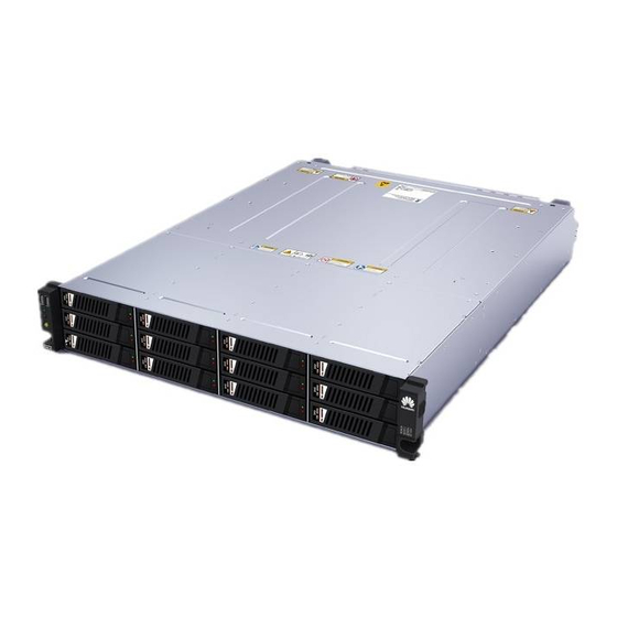
Page 12: Appearance
N2000H V3 Appliance User Guide 1 Product Overview Figure 1-1 N2000H V3 1.2 Appearance This topic describes the N2000H V3 panels. Front Panel Figure 1-2 shows the N2000H V3 front panel. Issue 04 (2018-11-06) Huawei Proprietary and Confidential Copyright © Huawei Technologies Co., Ltd. - Page 13 N2000H V3 Appliance User Guide 1 Product Overview Figure 1-2 N2000H V3 front panel Ethernet port indicator USB 2.0 port Hard disk fault indicator Hard disk active indicator Hard disks (numbered 0 to 23 from Fault diagnosis LED top down and from left to right)
- Page 14 Figure 1-3 are numbered as follows: − Numbered 24 to 35 from top down and from left to right when the N2000H V3 is equipped with one RAID controller card − Numbered 0 to 11 from top down and from left to right when the N2000H V3 is...
-
Page 15: Ports
Indicates the year and month (two characters). Indicates the serial number (six digits). 1.3 Ports This topic describes the ports on the N2000H V3. Table 1-2 Table 1-3 describe the external ports on the N2000H V3. Table 1-2 Ports on the front panel... -
Page 16: Indicators And Buttons
1.4 Indicators and Buttons This topic describes the indicators and buttons on the N2000H V3. You can observe the indicators to determine the status of the N2000H V3. Table 1-4 describes the indicators and buttons on the N2000H V3 front panel. - Page 17 Blinking yellow: The hard disk is being located, or the RAID is being reconstructed. Steady yellow: The hard disk is not detected or is faulty. Issue 04 (2018-11-06) Huawei Proprietary and Confidential Copyright © Huawei Technologies Co., Ltd.
- Page 18 If the NIC provides two network ports, they correspond to network port indicators 1 and 2 on the front panel. Table 1-5 describes the indicators on the N2000H V3 rear panel. Table 1-5 Indicators on the rear panel Indicator Color State ...
-
Page 19: Physical Structure
Steady yellow: The hard disk is not detected or is faulty. 1.5 Physical Structure This topic describes the N2000H V3 components. Figure 1-5 shows the N2000H V3 components. Issue 04 (2018-11-06) Huawei Proprietary and Confidential Copyright © Huawei Technologies Co., Ltd. - Page 20 N2000H V3 Appliance User Guide 1 Product Overview Figure 1-5 N2000H V3 components Rear hard disk module I/O module 2 (corresponding to CPU 2) PCIe card RAID controller card DIMM Heat sink Mainboard PSU backplane Hard disk Rear hard disk backplane for 12...
- Page 21 High-voltage (HV) DC PSUs: 240 V or 380 V NOTICE All the PSUs support double-pole/neutral fusing. The N2000H V3 supports one GE NIC with four GE ports. Both NICs support the Network Controller Sideband Interface (NC-SI). PCIe card The N2000H V3 provides two half-height half-length PCIe 3.0 x8 on the slots for standard PCIe cards.
- Page 22 Hz with 16 M colors. The backplane connects PSUs to the mainboard. backplane Hard disk The N2000H V3 uses hot-swappable hard disks to store data. It supports the following hard disk configurations: N2000H V3 with 36 + 4 hard disks: 24 front 3.5-inch SAS HDDs, SATA HDDs, or SSDs + 12 rear...
-
Page 23: Mainboard Layout
N2000H V3 Appliance User Guide 1 Product Overview 1.6 Mainboard Layout This topic describes the ports on the N2000H V3 mainboard. Figure 1-6 Figure 1-7 show the ports on the N2000H V3 mainboard. Figure 1-6 Mainboard layout (dual-CPU configuration) Serial port (J55 COM CONN ) -
Page 24: Internal Cabling
The ports on an RAID controller card may look different from the picture in this topic, depending on the card model. Signal cables to the front hard disk backplane Issue 04 (2018-11-06) Huawei Proprietary and Confidential Copyright © Huawei Technologies Co., Ltd. - Page 25 (J42) Signal cables for connecting the rear hard disk backplane for 12 disks to the front hard disk backplane when the N2000H V3 is equipped with a single RAID controller card Issue 04 (2018-11-06) Huawei Proprietary and Confidential Copyright © Huawei Technologies Co., Ltd.
- Page 26 The rear hard disk backplane for 12 disks is connected to the standard RAID controller card in a PCIe slot using SAS cables when the N2000H V3 is equipped with dual RAID controller cards. This topic assumes that a standard RAID controller card is installed in a PCIe x8 slot on the mainboard.
- Page 27 Signal cable for connecting the rear hard disk backplane (J1) for 12 disks to the front hard disk backplane (J36) Storage Power Cabling Power cables to the front hard disk backplane and the rear hard disk backplane for two disks Issue 04 (2018-11-06) Huawei Proprietary and Confidential Copyright © Huawei Technologies Co., Ltd.
- Page 28 Power cable for connecting the front hard disk backplane (J61 POWER) to the PSU backplane (J4) Power cable for connecting the rear hard disk backplane for 12 disks to the mainboard Issue 04 (2018-11-06) Huawei Proprietary and Confidential Copyright © Huawei Technologies Co., Ltd.
- Page 29 Figure 1-11 Power cable for connecting the rear hard disk backplane (J24 POWER) for 12 disks to the mainboard (J30 PWR CONN1) Front Mounting Ear Cabling Cables for connecting the front mounting ears on the left and right of the N2000H V3 to the mainboard Issue 04 (2018-11-06) Huawei Proprietary and Confidential Copyright ©...
-
Page 30: Logical Structure
PCIe slots of various specifications. A RAID controller card can be combined with the hard disk backplane to form a hard disk interface module, which connects to a CPU through PCIe connectors. The N2000H V3 supports a maximum of two E5-2600 v3 series CPUs. For details about the CPU positions, see 1.6 Mainboard Layout. -
Page 31: Ras Features
This topic describes the reliability, availability, and serviceability (RAS) features supported by the N2000H V3. Table 1-7 describes the RAS features supported by the N2000H V3. You can configure these features to improve Appliance RAS. For details about how to configure RAS features, see the... - Page 32 UEFI specifications, sends the error information to the OS over the APEI of the Advanced Configuration and Power Interface (ACPI), and locates the error unit, improving system availability. Issue 04 (2018-11-06) Huawei Proprietary and Confidential Copyright © Huawei Technologies Co., Ltd.
-
Page 33: Software And Hardware Compatibility
1.10 Software and Hardware Compatibility This topic describes the software and hardware compatibility supported by the N2000H V3. About the software and hardware compatibility supported by the N2000H V3, for more information, see the Compatibility. - Page 34 (ECC), memory mirroring, Single Device Data Correction (SDDC), memory sparing, and lockstep Storage The N2000H V3 supports the following hard disk configurations: − N2000H V3 with 36 + 4 hard disks: 24 front 3.5-inch SAS HDDs, SATA HDDs, or SSDs + 12 rear 3.5-inch SAS HDDs, SATA HDDs, or SSDs + 4 built-in 3.5-inch...
-
Page 35: Technical Specifications
Four GE optical ports, supporting NC-SI, WOL, and PXE PCIe slot The N2000H V3 provides one PCIe 3.0 x8 slot for the RAID controller card and 2 standard PCIe 3.0 x8 slots. The specifications for the five standard PCIe slots are described as follows: −... - Page 36 ≤ 3000 m (9842.40 ft) Altitude When the N2000H V3 is used at an altitude of higher than 900 m (2952.72 ft), the highest operating temperature decreases by 1° C (1.8° F) as the altitude increases by 300 m (984.24 ft).
- Page 37 LWAd: 53.0 Bels − LpAm: 70.3 dBA NOTE The actual sound levels generated when the Appliance is operating vary depending on the Appliance configuration, workload, and ambient temperature. Issue 04 (2018-11-06) Huawei Proprietary and Confidential Copyright © Huawei Technologies Co., Ltd.
-
Page 38: Installing And Removing The N2000H V3
For details about the safety instructions in the process of installing or replacing a Appliance or its parts, see the Safety in the Appliance Product Documentation. Checking the Installation Environment To ensure the proper installation and operating of the N2000H V3, plan the installation environment before installation, such as the rack, space, temperature, and humidity. Space Requirements... -
Page 39: Unpacking The Chassis
8% RH to 90% RH (non-condensing) Installation Rules The N2000H V3 is 4 U high and can be installed in a standard 19-inch rack. Multiple N2000H V3s can be stacked in a rack. If the rack space is sufficient, the distance between two adjacent Appliances is 1 U high. -
Page 40: Installing The N2000H V3
Service CD, Quick Start Guide, and Warranty card. A pair of guide rails. One rack Appliance. ----End 2.3 Installing the N2000H V3 This topic describes how to install the N2000H V3. Issue 04 (2018-11-06) Huawei Proprietary and Confidential Copyright © Huawei Technologies Co., Ltd. -
Page 41: Installing The N2000H V3 By Using L-Shaped Guide Rails
More N2000H V3s are required in a rack for capacity expansion. A faulty N2000H V3 needs to be replaced with a new N2000H V3. A different rack Appliance needs to be substituted by the N2000H V3. ... - Page 42 N2000H V3 Appliance User Guide 2 Installing and Removing the N2000H V3 Figure 2-1 Positions for installing floating nuts Step 2 Install floating nuts. Determine the position for installing a floating nut based on the installation plan. The floating nuts and screws are used together, to tighten the screws.
- Page 43 N2000H V3 Appliance User Guide 2 Installing and Removing the N2000H V3 Figure 2-3 Installing a floating nut Fasten the upper end of the floating nut to the mounting bar at the front of the rack by using the floating nut mounting bar.
-
Page 44: Installing The N2000H V3 By Using Adjustable Guide Rails
Step 4 Installing the N2000H V3 At least four persons lift the N2000H V3 on two sides and move it to the rack. Place the N2000H V3 on the guide rails and push it into the rack, as shown in Figure 2-5. - Page 45 N2000H V3 Appliance User Guide 2 Installing and Removing the N2000H V3 Figure 2-6 Positions for installing floating nuts Step 2 Install floating nuts. Determine the position for installing a floating nut based on the installation plan. The floating nuts and screws are used together, to tighten the screws.
- Page 46 N2000H V3 Appliance User Guide 2 Installing and Removing the N2000H V3 Figure 2-8 Installing a floating nut Fasten the upper end of the floating nut to the mounting bar at the front of the rack by using the floating nut mounting bar.
- Page 47 Step 4 Installing the N2000H V3 At least four persons lift the N2000H V3 on two sides and move it to the rack. Place the N2000H V3 on the guide rails and push it into the rack, as shown in Figure 2-10.
-
Page 48: Installing The N2000H V3 On Holding Rails
2 Installing and Removing the N2000H V3 Figure 2-10 Installing the N2000H V3 When the two mounting ears on the N2000H V3 contact the mounting bars on the rack, tighten the captive screws on the mounting ears to secure the N2000H V3. - Page 49 N2000H V3 Appliance User Guide 2 Installing and Removing the N2000H V3 Figure 2-11 Installing the front end and rear end of the holding rail Step 2 Install the Appliance. Pull out an inner rail from a holding rail until the inner rail cannot move, push the release button upward, and remove the inner rail from the holding rail.
- Page 50 N2000H V3 Appliance User Guide 2 Installing and Removing the N2000H V3 Figure 2-12 Removing an inner rail Align the inner rail with the fastening screw on one side of the Appliance, and push the inner rail forward so that the inner rail is secured to the Appliance. See Figure 2-13.
- Page 51 N2000H V3 Appliance User Guide 2 Installing and Removing the N2000H V3 Figure 2-13 Installing an inner rail Use the same method to install another inner rail on the opposite side of the Appliance. Lift the Appliance, align the inner rails with the holding rails, and push the Appliance into the rack.
- Page 52 N2000H V3 Appliance User Guide 2 Installing and Removing the N2000H V3 Figure 2-14 Installing a Appliance on holding rails Press the release buttons on both sides, and push the Appliance into the rack until the Appliance cannot move forward. See Figure 2-15.
- Page 53 N2000H V3 Appliance User Guide 2 Installing and Removing the N2000H V3 Figure 2-15 Pushing a Appliance into a rack Tighten the captive screws on the mounting ears to secure the Appliance. See Figure 2-16. Issue 04 (2018-11-06) Huawei Proprietary and Confidential...
- Page 54 N2000H V3 Appliance User Guide 2 Installing and Removing the N2000H V3 Figure 2-16 Securing a Appliance Step 3 Install a cabling rack. Insert the support lever into the outer rails on both left and right sides. See step (1) in Figure 2-17.
-
Page 55: Connecting External Cables
N2000H V3 Appliance User Guide 2 Installing and Removing the N2000H V3 Figure 2-17 Installing a cabling rack ----End 2.4 Connecting External Cables This topic describes how to connect cables for the Appliance. 2.4.1 Connecting Cables to a Mouse, Keyboard, and VGA Port... - Page 56 N2000H V3 Appliance User Guide 2 Installing and Removing the N2000H V3 The rear panel of the Appliance provides a DB15 VGA port but no standard PS/2 port for a keyboard or mouse. You can connect a keyboard and mouse to USB ports on the front or rear panel based on site installation conditions.
-
Page 57: Connecting A Network Cable
N2000H V3 Appliance User Guide 2 Installing and Removing the N2000H V3 2.4.2 Connecting a network cable Scenarios Connect a network cable in the following scenarios: The network is to be set up over a gigabit Ethernet (GE). ... - Page 58 N2000H V3 Appliance User Guide 2 Installing and Removing the N2000H V3 Route the new network cable in the same mode as the network cable to be replaced. Note the following points: Underfloor cabling is recommended because it is tidy and easy to route. Route cables in the rack based on the installation requirements.
-
Page 59: Connecting A Cable To A 10Ge Port
N2000H V3 Appliance User Guide 2 Installing and Removing the N2000H V3 Step 6 Connect the other end of the network cable to the peer network port. Connect the other cable connector to the peer device based on the network plan. Note the following: ... - Page 60 N2000H V3 Appliance User Guide 2 Installing and Removing the N2000H V3 The new cable must have the same number as the old one. Use the same type of labels for optical fibers. Record the name and number of the local device to be connected on one side of an optical fiber and those of the peer device on the other side.
- Page 61 N2000H V3 Appliance User Guide 2 Installing and Removing the N2000H V3 Figure 2-20 Connecting an optical fiber Step 5 When you use an SFP+ cable: Remove the old SFP+ cable. Gently push the power connector inwards and pull out the latch to remove the SFP+ cable.
- Page 62 N2000H V3 Appliance User Guide 2 Installing and Removing the N2000H V3 Figure 2-21 Removing an SFP+ cable Connect the new SFP+ cable. Remove the dust-proof cap of the port, and insert the cable connector into the port. See Figure 2-22.
-
Page 63: Connecting A Usb Device
N2000H V3 Appliance User Guide 2 Installing and Removing the N2000H V3 Power on the device, and ping the IP address of the peer device connected over the new cable. If the peer device cannot be pinged, check that the cable is intact or the connector is securely connected. -
Page 64: Connecting A Serial Cable
N2000H V3 Appliance User Guide 2 Installing and Removing the N2000H V3 Figure 2-23 Connecting a USB device ----End 2.4.5 Connecting a Serial Cable Scenarios The Appliance provides one standard DB9 serial port on the rear, which works as the system serial port by default. -
Page 65: Connecting A Power Cable
N2000H V3 Appliance User Guide 2 Installing and Removing the N2000H V3 Documents For details about the command for setting the serial port to the iBMC serial port, see the HUAWEI Rack Appliance iBMC User Guide. Hardware The serial cable uses a DB9 connector. - Page 66 N2000H V3 Appliance User Guide 2 Installing and Removing the N2000H V3 A new PSU is to be powered on after being installed. The following describes how to connect AC and DC power cables. Prerequisites Conditions The power cable must be securely connected.
- Page 67 N2000H V3 Appliance User Guide 2 Installing and Removing the N2000H V3 Insert the other end of the AC power cable into the AC power socket on the rack. The AC power socket is horizontally secured at the rear of the rack. Select the jacks on the nearest socket for connection.
-
Page 68: Cable Routing
N2000H V3 Appliance User Guide 2 Installing and Removing the N2000H V3 2.4.7 Cable Routing Basic Rules Different types of cables should be separately routed and bound. The cables of the same type are routed in the same direction. Cables at a small distance can be routed in crossover mode. -
Page 69: Verifying Cable Connections
Its component is to be replaced. Devices are to be relocated. Impact on the System The services and programs running on the N2000H V3 will be interrupted when it is removed. Prerequisites Conditions Issue 04 (2018-11-06) Huawei Proprietary and Confidential... - Page 70 Step 3 Loosen the captive screws on the N2000H V3 panel using a screwdriver. See step (1) in Figure 2-27. Figure 2-27 Removing the N2000H V3 Step 4 Pull out the N2000H V3 along the guide rails away from the rack. See step (2) in Figure 2-27. Issue 04 (2018-11-06) Huawei Proprietary and Confidential Copyright ©...
- Page 71 N2000H V3 Appliance User Guide 2 Installing and Removing the N2000H V3 Step 5 Place the removed N2000H V3 on the ESD platform for maintenance, for example, parts replacement. ----End Issue 04 (2018-11-06) Huawei Proprietary and Confidential Copyright © Huawei Technologies Co., Ltd.
-
Page 72: Powering On And Off The N2000H V3
N2000H V3 Appliance User Guide 3 Powering On and Off the N2000H V3 Powering On and Off the N2000H V3 About This Chapter This topic describes the precautions and procedures for powering on and off the Appliance. 3.1 Powering On This topic describes how to power on the Appliance. -
Page 73: Powering Off
N2000H V3 Appliance User Guide 3 Powering On and Off the N2000H V3 For details about how to obtain the IP address for the management network port and how to operate the iBMC, see the HUAWEI Rack Appliance iBMC User Guide. - Page 74 N2000H V3 Appliance User Guide 3 Powering On and Off the N2000H V3 You have obtained the IP address, user name, and user password for the management network port on the iBMC. Tools Electrostatic discharge (ESD) wrist strap or ESD gloves: used to prevent ESD damage.
-
Page 75: Configuring The N2000H V3
This topic describes how to change an iBMC user password. 4.6 Installing an OS This topic describes how to install an operating system (OS) for the N2000H V3. 4.1 Configuration Overview This topic describes the default information and the initial configuration process. -
Page 76: Configuration Process
N2000H V3 Appliance User Guide 4 Configuring the N2000H V3 Table 4-1 Default information Item Parameter Default Value iBMC management IP address and subnet Default IP address: 192.168.2.100 network port mask of the Default subnet mask: 255.255.255.0 information... -
Page 77: Checking The N2000H V3
This topic describes how to check the N2000H V3 initial status. Scenarios Log in to the iBMC WebUI or CLI to check the health status of the N2000H V3. Ensure that its health status meets the environment requirements for software installation. - Page 78 For details about the CLI, see the HUAWEI Rack Appliance iBMC User Guide. Workflow Check the N2000H V3 by following the sequence described in Figure 4-2. Determine the checking method based on actual site requirements. Figure 4-2 Process for checking the N2000H V3 Procedure ...
- Page 79 N2000H V3 Appliance User Guide 4 Configuring the N2000H V3 Observe the N2000H V3 indicator status, and check that hardware devices are properly operating. For details, see . Check the N2000H V3 using the iBMC WebUI. Log in to the iBMC over the WebUI.
- Page 80 Set an IP address for the PC, and ensure that the IP address is on the same network segment as the iBMC management network port. Connect the PC to the N2000H V3 iBMC management network port by using a network cable.
-
Page 81: Configuring Raid Properties
BIOS Version: indicates the basic input/output system (BIOS) version of the N2000H V3. Active iBMC Version: indicates the active iBMC version of the N2000H V3. Backup iBMC Version: indicates the backup iBMC version of the N2000H Query the health status for the N2000H V3. - Page 82 N2000H V3 Appliance User Guide 4 Configuring the N2000H V3 Figure 4-5 Boot information displayed for the LSISAS2308 controller card The preceding information is for reference only. The actual information may be different from the example. LSISAS3008 controller card Press Ctrl-C to Start LSI Corp Configuration Utility...
- Page 83 N2000H V3 Appliance User Guide 4 Configuring the N2000H V3 On the menu bar, choose Information, in the navigation tree, choose Component Info. The Component Info page is displayed. View the RAID controller card information, as shown in Figure 4-8.
- Page 84 N2000H V3 Appliance User Guide 4 Configuring the N2000H V3 Figure 4-9 LSISAS2308 controller card LSISAS3008 controller card Figure 4-10 shows the LSISAS3008 controller cards. Figure 4-10 LSISAS3008 controller card LSISAS3108 controller card Figure 4-11 shows the LSISAS3108 controller cards.
-
Page 85: Configuring The Bios
4.4 Configuring the BIOS This topic describes how to configure the basic input/output system (BIOS) for the N2000H Scenarios Configure the BIOS for the N2000H V3 in remote control mode. The configuration items are as follows: Appliance boot mode ... - Page 86 N2000H V3 Appliance User Guide 4 Configuring the N2000H V3 Figure 4-12 Process for configuring the BIOS Procedure Restart the Appliance. Click on the menu bar on the remote virtual console. For details about how to log in to the remote virtual console, see 7.4 Logging In to the...
- Page 87 N2000H V3 Appliance User Guide 4 Configuring the N2000H V3 Figure 4-13 BIOS startup screen Enter a BIOS password as prompted. The screen for setting the BIOS is displayed. The default BIOS password is Huawei12#$. To ensure system security, you are advised to change the default BIOS password after the first login.
- Page 88 Figure 4-14 Boot Type Order When Hard Disk Drive is selected as the boot option for the N2000H V3 with two RAID controller cards, to avoid a failure to display the boot option for installing the OS due to insufficient BIOS space, you are advised to disable the other RAID boot options.
- Page 89 N2000H V3 Appliance User Guide 4 Configuring the N2000H V3 Figure 4-15 PXE Configuration 11. Select the network port to be configured, and press Enter. 12. Choose Enabled from the shortcut menu and press Enter to enable the PXE function for the NIC.
-
Page 90: Changing An Ibmc User Password
N2000H V3 Appliance User Guide 4 Configuring the N2000H V3 Figure 4-16 Security 14. Select Set Supervisor Password, and press Enter. Set a login password for the super administrator. Before changing the supervisor password, you need to enter the current supervisor password. - Page 91 N2000H V3 Appliance User Guide 4 Configuring the N2000H V3 Change the default password promptly and change the user password periodically to ensure system security. Impact on the System This operation has no adverse impact on the system. Prerequisites Conditions You have logged in to the iBMC WebUI over a network port.
-
Page 92: Installing An Os
N2000H V3 Appliance User Guide 4 Configuring the N2000H V3 Figure 4-17 Local User page Step 2 Click next to the user whose password is to be changed. Step 3 Change the password as prompted. ----End 4.6 Installing an OS This topic describes how to install an operating system (Windows Storage Server 2012 R2) for the N2000 V3. -
Page 93: Os Installation
N2000H V3 Appliance User Guide 4 Configuring the N2000H V3 Figure 4-18 Initial configuration Step 2 Set the SATA DOM as the default boot devices for the BIOS, just see chapter 4.4 for reference. Step 3 And then, enter “F10” to save the configuration, and reboot the system. - Page 94 N2000H V3 Appliance User Guide 4 Configuring the N2000H V3 Figure 4-20 Select the DVD as the boot device Step 4 Press any key to boot from the DVD. Issue 04 (2018-11-06) Huawei Proprietary and Confidential Copyright © Huawei Technologies Co., Ltd.
- Page 95 N2000H V3 Appliance User Guide 4 Configuring the N2000H V3 Figure 4-21 Boot from the DVD Figure 4-22 Windows setup Step 5 At the beginning of the installation, select the language and the data & time format. Issue 04 (2018-11-06) Huawei Proprietary and Confidential Copyright ©...
- Page 96 N2000H V3 Appliance User Guide 4 Configuring the N2000H V3 Figure 4-23 Select the language and other preferences Step 6 Select the “Install now” to continue. Figure 4-24 Press the Install now Issue 04 (2018-11-06) Huawei Proprietary and Confidential Copyright © Huawei Technologies Co., Ltd.
- Page 97 N2000H V3 Appliance User Guide 4 Configuring the N2000H V3 Step 7 Input the key to activate the Windows. Figure 4-25 Input the key purchased Step 8 Confirm and accept the license, and continue. Issue 04 (2018-11-06) Huawei Proprietary and Confidential...
- Page 98 N2000H V3 Appliance User Guide 4 Configuring the N2000H V3 Figure 4-26 Accept the license and next Step 9 Select the custom to continue for the fresh installation. Figure 4-27 Custom to install Issue 04 (2018-11-06) Huawei Proprietary and Confidential...
- Page 99 N2000H V3 Appliance User Guide 4 Configuring the N2000H V3 Step 10 Select the SATA DOM as the device to install, and partitioning. Figure 4-28 Select the SATADOM (Total size=128GB ), and portioning Step 11 The OS will install automatically, and after the installation, a reboot would be executed automatically.
- Page 100 N2000H V3 Appliance User Guide 4 Configuring the N2000H V3 Figure 4-29 Installation is undergoing Step 12 After the reboot, the password should be input. Step 13 Finally, the installation is completed. You could press “Ctrl + Alt + Delete” to login the system.
-
Page 101: Service Configuration
N2000H V3 Appliance User Guide 4 Configuring the N2000H V3 4.7 Service configuration 4.7.1 Configuring Basic Features This section explains how to create volumes, check the factory configuration, and configure local users and user groups. 4.7.1.1 Creating Volumes In the process of installing Windows Storage Server 2012 on the N2000 server at the factory, only the volume where Windows Storage Server 2012 resides is created, and the remaining disk space is reserved. -
Page 102: Checking The Factory Configuration
N2000H V3 Appliance User Guide 4 Configuring the N2000H V3 Click Select Folder. You are returned the Drive Letter or Folder page. Click Next. Step 7 Set file system parameters. On the File System Settings page, the following parameters are displayed: ... -
Page 103: Configuring Local Users And User Groups
N2000H V3 Appliance User Guide 4 Configuring the N2000H V3 Step 3 On the Installation Type page, click Role-based or feature-based installation and then click Next. Step 4 On the Server Selection page, click Select a server from the server pool and select the local server. - Page 104 N2000H V3 Appliance User Guide 4 Configuring the N2000H V3 Procedure Step 1 Choose Tools > Computer Management from the menu bar of the Server Manager that is automatically started after a login to the operating system. Step 2 In the Computer Management window, double-click the Local Users and Groups node in the navigation tree.
-
Page 105: Configuring Sharing Features
N2000H V3 Appliance User Guide 4 Configuring the N2000H V3 Parameter Description Example Account is If this option is selected, the user account is You are advised not to disabled disabled. This option is applicable to a user select this option. - Page 106 N2000H V3 Appliance User Guide 4 Configuring the N2000H V3 You have logged in to Windows Storage Server 2012. Procedure Step 1 Choose File and Storage Services > Shares from the navigation tree of the Server Manager that is automatically started after a login to the operating system.
- Page 107 N2000H V3 Appliance User Guide 4 Configuring the N2000H V3 Set Type to Allow. Set Permissions for the user. For example, select Read. Click OK. Click Next. The Management Properties page is displayed. Step 8 Set management properties.
-
Page 108: Configuring An Nfs Share
N2000H V3 Appliance User Guide 4 Configuring the N2000H V3 Result After configuring a CIFS share, perform the following steps to check whether the parameters are set successfully: On a computer that runs a Windows operating system, choose Start > Run. - Page 109 N2000H V3 Appliance User Guide 4 Configuring the N2000H V3 Select by volume enables you to specify the volume you want to share. In this mode, the system automatically creates a shares folder in the root path on the specified volume and uses shares as the shared folder.
- Page 110 N2000H V3 Appliance User Guide 4 Configuring the N2000H V3 Step 9 Set management properties. Select the Folder Usage value for this folder specifies the folder usage and the types of files stored in the folder. Select options based on the actual service plan.
-
Page 111: Configuring An Ftp Share
N2000H V3 Appliance User Guide 4 Configuring the N2000H V3 example, if you want to prohibit audio and video files from being stored in the specified folder, select Block Audio and Video Files. Click Create. ----End Result After configuring an NFS share, perform the following steps to check whether the parameters... - Page 112 N2000H V3 Appliance User Guide 4 Configuring the N2000H V3 If a dialog box showing a message is displayed, close the dialog box and continue with subsequent operations. Step 3 Configure FTP site information. Set FTP site name to the name of an FTP share, for example, FTP-department1.
-
Page 113: Configuring An Http Share
N2000H V3 Appliance User Guide 4 Configuring the N2000H V3 Result After configuring an FTP share, perform the following steps to check whether the parameters are set successfully: On a computer that serves as an FTP client, start an FTP tool. This section uses the FileZilla as an example. - Page 114 N2000H V3 Appliance User Guide 4 Configuring the N2000H V3 In the navigation tree of Internet Information Service(IIS) Manager, choose the website. In the information area, double-click Directory Browsing. In the Actions area, click Enable. Step 7 Configure identity authentication.
-
Page 115: Configuring Value-Added Features
N2000H V3 Appliance User Guide 4 Configuring the N2000H V3 Press Enter to log in to the shared server. Open Shared Folder 1 and view the contents in the folder. 4.7.3 Configuring Value-Added Features This section explains how to configure and manage value-added features such as deduplication, Internet Small Computer System Interface (iSCSI) target server, BranchCache, distributed file system (DFS), and Hyper-V. -
Page 116: Configuring The Iscsi Target Server
N2000H V3 Appliance User Guide 4 Configuring the N2000H V3 Parameter Description Example week Thursday, and Friday. Start Specifies the start time from which Set Start time to 0:00 time deduplication tasks are carried out. so that deduplication tasks are carried out when the traffic is light. - Page 117 N2000H V3 Appliance User Guide 4 Configuring the N2000H V3 Prerequisites The hardware of the N2000 server has been installed and powered on. You have logged in to Windows Storage Server 2012. Procedure Step 1 Choose Dashboard > Add roles and features from the navigation tree of the Server Manager that is automatically started after a login to the operating system.
- Page 118 N2000H V3 Appliance User Guide 4 Configuring the N2000H V3 On the iSCSI Virtual Disk Size page, specify the capacity of the virtual disk you want to create and then click Next. The maximum capacity that can be allocated is the remaining capacity of the volume where the virtual disk resides, and the granularity can be TB, GB, and MB.
-
Page 119: Configuring Branchcache (Hosted Cache Mode)
N2000H V3 Appliance User Guide 4 Configuring the N2000H V3 4.7.3.10 Configuring BranchCache (Hosted Cache Mode) BranchCache is a technology that decreases the WAN link utilization and accelerates responses to branches' accesses to a remote server. Clients in a branch use locally cached data to decrease the traffic over WAN links. - Page 120 N2000H V3 Appliance User Guide 4 Configuring the N2000H V3 In the Options area, Allow hash publication only for shared folders on which BranchCache is enabled is generated by default, indicating that hash values are calculated and released only for a CIFS shared folder that has the BranchCache feature enabled.
- Page 121 N2000H V3 Appliance User Guide 4 Configuring the N2000H V3 thumbprint indicates the recorded fingerprint character string. You must set thumbprint to a character string that does not contain any space. Step 6 On the cache server, configure firewall policies.
-
Page 122: Configuring Branchcache (Distributed Cache Mode)
N2000H V3 Appliance User Guide 4 Configuring the N2000H V3 On the desktop, click the Windows Powershell shortcut icon on the taskbar to invoke the Powershell command line tool. Run the gpedit.msc command to invoke Local Group Policy Editor. In the navigation tree of Local Group Policy Editor, choose Computer Configuration >... - Page 123 N2000H V3 Appliance User Guide 4 Configuring the N2000H V3 On the Installation Type page, click Role-based or feature-based installation and then click Next. On the Server Selection page, click Select a server from the server pool and select the local server.
-
Page 124: Configuring Dfs
N2000H V3 Appliance User Guide 4 Configuring the N2000H V3 You need to set only Inbound Rules on a client. On the desktop, click the Windows Powershell shortcut icon on the taskbar to invoke the Powershell command line tool. Run the gpedit.msc command to invoke Local Group Policy Editor. - Page 125 N2000H V3 Appliance User Guide 4 Configuring the N2000H V3 Step 7 After you confirm that the parameters are set correctly, click Create. Step 8 Wait until Status of the Create Namespace task changes to Success. Then, click Close. The name of the newly created namespace is displayed under the Namespaces node in the DFS management navigation tree.
- Page 126 N2000H V3 Appliance User Guide 4 Configuring the N2000H V3 No topology: This option is not recommended. Step 14 On the Replication Group Schedule and Bandwidth page, set the replication bandwidth and schedule. Then, click Next. Select the desired bandwidth from the Bandwidth drop-down list, for example, 4Mbps.
-
Page 127: System Security Policy
This topic describes how to update the appliance system. 5.1 System Security Reinforce Before shipment, the Windows Storage Server 2012 R2 system of the appliance has implemented some security reinforce, according to the Security Red-line of the Huawei. The detailed policy is listed below. 5.1.1 Security Settings Security ... - Page 128 N2000H V3 Appliance User Guide 5 System Security Policy Desktop and Explorer Restrict the Screen Saver: Disabled Screen Saver password protection policy: No Action Security Options Accounts Block Microsoft accounts: Users can't add or log on with Microsoft accounts ...
- Page 129 N2000H V3 Appliance User Guide 5 System Security Policy Send unencrypted password to connect to third-party SMB Server: Disabled Microsoft Network Server Amount of idle time required before disconnecting session: 15 minutes Digitally sign communications (always): Enabled ...
- Page 130 N2000H V3 Appliance User Guide 5 System Security Policy Configure encryption types allowed for Kerberos: DES_CBC_CRC, DES_CBC_MD5, RC4_HMAC_MD5, AES128_HMAC_SHA1, Future encryption types Do not store LAN Manager password hash value on next password change: Enabled Force logoff when logon hours expire: Enabled ...
-
Page 131: Auditing And Account Policies
N2000H V3 Appliance User Guide 5 System Security Policy Always install with elevated privileges: Disabled 5.1.2 Auditing and Account policies Account Lockout Policy Account lockout duration: 15 minutes Account lockout threshold: 10 invalid logon attempts Reset account lockout counter after: 15 minutes Account Policy ... -
Page 132: Administrative Templates
N2000H V3 Appliance User Guide 5 System Security Policy Object Access Audit Removable Storage: Success & Failure Policy Change Advance Audit Policy Change: Success & Failure Advance Authentication Policy Change: Success Privilege Use ... - Page 133 N2000H V3 Appliance User Guide 5 System Security Policy Turn off the "Publish to Web" task for files and folders: Enabled Turn off the Windows Messenger Customer Experience Improvement Program: Enabled System Early Launch Antimalware Boot-Start Driver Initialization Policy: Good,unknown and bad but critical ...
- Page 134 N2000H V3 Appliance User Guide 5 System Security Policy Windows Remote Management (WinRM) WinRM Client Disallow Digest authentication: Enabled WinRM Client:Allow Basic authentication: Disabled WinRM Client:Allow unencrypted traffic: Disabled WinRM Service Disallow WinRM from storing RunAs credentials: Enabled ...
-
Page 135: Additional Security Protection
N2000H V3 Appliance User Guide 5 System Security Policy Log successful connections (Private): Yes Name (Private): %SYSTEMROOT%\System32\logfiles\firewall\privatefw.log Size limit(KB) (Private): 16384 Public Allow unicast response(Public): No Apply local connection security rules (Public): No ... - Page 136 N2000H V3 Appliance User Guide 5 System Security Policy Access this computer from the network: Administrators,NT AUTHORITY\Authenticated Users Act as part of the operating system: Add workstations to domain: Administrators Adjust memory quotas for a process: Administrators,NT AUTHORITY\LOCAL SERVICE,NT AUTHORITY\NETWORK SERVICE ...
-
Page 137: System Patch Update
N2000H V3 Appliance User Guide 5 System Security Policy Perform volume maintenance tasks: Administrators Profile single process: Administrators Profile system performance: Administrators,NT SERVICE\NT SERVICE Replace a process level token: NT AUTHORITY\LOCAL SERVICE,NT AUTHORITY\NETWORK SERVICE Restore files and directories: Administrators ... -
Page 138: Update Manually
N2000H V3 Appliance User Guide 5 System Security Policy Figure 5-2 View the update history 5.2.2 Update manually Step 1 Log on the update web site of the Microsoft as below: http://catalog.update.microsoft.com/v7/site/home.aspx Step 2 Input “Windows Storage Server 2012 R2” in the Search window, then all of the update for windows Storage Server 2012 R2 would be displayed. - Page 139 N2000H V3 Appliance User Guide 5 System Security Policy Figure 5-3 View update history Issue 04 (2018-11-06) Huawei Proprietary and Confidential Copyright © Huawei Technologies Co., Ltd.
-
Page 140: Security Maintenance Policy
A real-time update policy is recommended for the antivirus library. If a manually update policy is configured by customers, the antivirus library should be updated synchronized with the manufacture of the antivirus software. Issue 04 (2018-11-06) Huawei Proprietary and Confidential Copyright © Huawei Technologies Co., Ltd. -
Page 141: Replacing Parts
This topic describes how to remove the chassis cover from the N2000H V3 before replacing any N2000H V3 part in the chassis. 7.7 Installing a Chassis Cover This topic describes how to install the chassis cover for the N2000H V3 after replacing one or more N2000H V3 parts. 7.8 Removing the Air Duct This topic describes how to remove the air duct. - Page 142 This topic describes how to install a supercapacitor. 7.26 Removing a CPU This topic describes how to remove a CPU before replacing it with a new one. Issue 04 (2018-11-06) Huawei Proprietary and Confidential Copyright © Huawei Technologies Co., Ltd.
- Page 143 7.40 Removing the Rear Hard Disk Backplane This topic describes how to remove the rear hard disk backplane before replacing it with a new one. 7.41 Installing a Rear Hard Disk Backplane Issue 04 (2018-11-06) Huawei Proprietary and Confidential Copyright © Huawei Technologies Co., Ltd.
-
Page 144: Replaceable Parts
This topic describes how to install a front mounting ear plate. 7.1 Replaceable Parts This topic describes the replaceable parts of the N2000H V3. The N2000H V3 is 4U high and has the following replaceable parts: Hard disk ... -
Page 145: Removing A Hard Disk
Do not power off the N2000H V3 when removing a hard disk. Prerequisites Conditions If services are running on the N2000H V3, you have backed up the data on the hard disk to be removed and delete RAID configuration from the hard disk. Data ... - Page 146 Step 3 Hold the ejector lever, and pull out the hard disk for about 3 cm (1.18 in.). See step (2) in Figure 5-2. Wait for at least 30 seconds until the hard disk stops working. Then remove the hard disk from the N2000H V3. See step (3) in Figure 5-2.
-
Page 147: Installing A Hard Disk
A hard disk has no free space. A hard disk is to be added. You do not need to power off the N2000H V3 before installing a hard disk. Prerequisites Conditions No special condition is required for this operation. - Page 148 See step (2) in Figure 5-4. Observe the hard disk indicators to check the hard disk operating status. For details about the indicators, see 1.4 Indicators and Buttons. ----End Issue 04 (2018-11-06) Huawei Proprietary and Confidential Copyright © Huawei Technologies Co., Ltd.
-
Page 149: Removing A Psu
ESD gloves or ESD wrist strap Packaging materials, for example, an ESD bag Procedure Step 1 (Optional) If only one PSU is configured, power off the N2000H V3. For details, see Powering Off. Step 2 Open the cable tie for the power cable. See Figure 5-5. - Page 150 Step 4 Press the spring on the PSU in the arrow direction, and pull the PSU out of the slot while holding the handle. See steps (1) and (2) in Figure 5-7. Issue 04 (2018-11-06) Huawei Proprietary and Confidential Copyright © Huawei Technologies Co., Ltd.
-
Page 151: Removing A Dc Psu
A DC PSU is to be replaced with a new model. Prerequisites Conditions When two PSUs are configured, remove one PSU without powering off the N2000H V3 if the other PSU is operating properly. Observe the PSU indicators to check the PSU operating status. For details about the indicators, see 1.4 Indicators and... - Page 152 7 Replacing Parts You have obtained the rack number and chassis number of the N2000H V3. You have located the N2000H V3 based on the preceding information, and labeled its panel to prevent misoperations. Tools ESD gloves or ESD wrist strap ...
-
Page 153: Installing A Psu
An AC PSU is to be replaced with a new model. An AC PSU is to be added to improve reliability when only one AC PSU is configured for the N2000H V3. Prerequisites Conditions None Issue 04 (2018-11-06) Huawei Proprietary and Confidential Copyright © Huawei Technologies Co., Ltd. - Page 154 You have determined the position on the N2000H V3 for installing a PSU. You have obtained the rack number and chassis number of the N2000H V3. You have located the N2000H V3 based on the preceding information, and labeled its panel to prevent misoperations. Tools ...
-
Page 155: Installing A Dc Psu
Step 4 Secure the power cable using a cable tie. See Figure 5-12. Figure 7-12 Securing a power cable ----End 7.5.2 Installing a DC PSU This topic describes how to install a DC power supply unit (PSU). Issue 04 (2018-11-06) Huawei Proprietary and Confidential Copyright © Huawei Technologies Co., Ltd. - Page 156 A DC PSU fails. A DC PSU is to be replaced with a new model. A DC PSU is to be added to improve reliability when the N2000H V3 is configured with only one DC PSU. Prerequisites Conditions...
- Page 157 Connect the OT terminal on the positive power cable to the RTN(+) wiring terminal on the PSU. Connect the OT terminal on the ground cable to the ground terminal on the PSU. Issue 04 (2018-11-06) Huawei Proprietary and Confidential Copyright © Huawei Technologies Co., Ltd.
-
Page 158: Removing The Chassis Cover
This topic describes how to remove the chassis cover from the N2000H V3 before replacing any N2000H V3 part in the chassis. Scenarios Remove the chassis cover from the N2000H V3 before replacing any N2000H V3 part in the chassis. Prerequisites Conditions ... -
Page 159: Installing A Chassis Cover
Figure 5-15. ----End 7.7 Installing a Chassis Cover This topic describes how to install the chassis cover for the N2000H V3 after replacing one or more N2000H V3 parts. Issue 04 (2018-11-06) Huawei Proprietary and Confidential Copyright © Huawei Technologies Co., Ltd. - Page 160 Scenarios Install the chassis cover after replacing parts for the N2000H V3. Prerequisites Conditions You have removed the N2000H V3 from the rack and the components in the chassis are replaced. For details, see 2.5 Removing the N2000H Data ...
-
Page 161: Removing The Air Duct
Remove the air duct in any of the following scenarios: The air duct fails. A CPU, dual in-line memory module (DIMM), or supercapacitor is to be replaced. Prerequisites Conditions Issue 04 (2018-11-06) Huawei Proprietary and Confidential Copyright © Huawei Technologies Co., Ltd. - Page 162 Removing the Chassis Cover. Data You have determined the position on the N2000H V3 for removing the air duct. You have obtained the rack number and chassis number of the N2000H V3. You have located the N2000H V3 based on the preceding information, and labeled its panel to prevent misoperations.
-
Page 163: Installing An Air Duct
You have determined the position on the N2000H V3 for installing an air duct. You have obtained the rack number and chassis number of the N2000H V3, and labeled its panel to prevent misoperations. Tools Issue 04 (2018-11-06) Huawei Proprietary and Confidential Copyright ©... - Page 164 See Figure 5-19. Figure 7-19 Installing an air duct Step 3 Optional: Install the supercapacitor tray on the air duct in the arrow direction. See Figure 5-20. Issue 04 (2018-11-06) Huawei Proprietary and Confidential Copyright © Huawei Technologies Co., Ltd.
-
Page 165: Removing A Fan Module
Removing the Chassis Cover. Data You have determined the position on the N2000H V3 for removing a fan module. You have obtained the rack number and chassis number of the N2000H V3. You have located the N2000H V3 based on the preceding information, and labeled its panel to prevent misoperations. -
Page 166: Installing A Fan Module
7 Replacing Parts Packaging materials, for example, an ESD bag Procedure Step 1 Lift the fan module slowly out of the N2000H V3. See in Figure 5-21. Step 2 Remove the fan module from the slot. Figure 7-21 Removing a fan module Step 3 Place the removed fan module in an ESD bag. - Page 167 Data You have determined the position on the N2000H V3 for installing a fan module. You have obtained the rack number and chassis number of the N2000H V3, and labeled its panel to prevent misoperations. Tools ESD gloves ...
-
Page 168: Removing The Riser Card
This topic describes how to remove the riser card before replacing it with a new one. Scenarios Remove the riser card in any of the following scenarios: The riser card fails. The mainboard is to be removed. Prerequisites Conditions Issue 04 (2018-11-06) Huawei Proprietary and Confidential Copyright © Huawei Technologies Co., Ltd. - Page 169 Data You have determined the position on the N2000H V3 for removing the riser card. You have obtained the rack number and chassis number of the N2000H V3, and labeled its panel to prevent misoperations. Tools ESD gloves ...
-
Page 170: Installing A Riser Card
Data You have determined the position on the N2000H V3 for installing a riser card. You have obtained the rack number and chassis number of the N2000H V3, and labeled its panel to prevent misoperations. Tools ESD gloves ... - Page 171 Step 4 Install a PCIe card on the riser card. For details, see 5.15.1 Installing a PCIe Card on the Riser Card. Step 5 Install the riser card tray. See step in Figure 5-26. Issue 04 (2018-11-06) Huawei Proprietary and Confidential Copyright © Huawei Technologies Co., Ltd.
-
Page 172: Removing A Pcie Card
A PCIe card is to be replaced with a new model. Prerequisites Conditions You have powered off the N2000H V3. For details, see 3.2 Powering Off. Issue 04 (2018-11-06) Huawei Proprietary and Confidential Copyright © Huawei Technologies Co., Ltd. - Page 173 You have removed the chassis cover from the N2000H V3. For details, see Removing the Chassis Cover. You have removed the riser card tray from the N2000H V3. For details, see 5.12 Removing the Riser Card. Data ...
-
Page 174: Removing A Pcie Card From The Mainboard
Removing the Chassis Cover. Data You have determined the position on the N2000H V3 for removing a PCIe card. You have obtained the rack number and chassis number of the N2000H V3. You have located the N2000H V3 based on the preceding information, and labeled its panel to prevent misoperations. -
Page 175: Installing A Pcie Card
This topic describes how to install a Peripheral Component Interconnect Express (PCIe) card on the riser card. Scenarios Install a PCIe card. Prerequisites Conditions You have powered off the N2000H V3. For details, see 3.2 Powering Off. Issue 04 (2018-11-06) Huawei Proprietary and Confidential Copyright © Huawei Technologies Co., Ltd. - Page 176 You have determined the position on the N2000H V3 for installing a PCIe card. You have obtained the rack number, chassis number, and slot number of the N2000H V3, and labeled its panel to prevent misoperations. Tools ...
-
Page 177: Installing A Pcie Card On The Mainboard
Removing the Chassis Cover. Data You have determined the position on the N2000H V3 for installing a PCIe card. You have obtained the rack number and chassis number of the N2000H V3. You have located the N2000H V3 based on the preceding information, and labeled its panel to prevent misoperations. -
Page 178: Removing A Tpm
You have removed the N2000H V3 from the rack. For details, see 2.5 Removing the N2000H You have removed the chassis cover from the N2000H V3. For details, see Removing the Chassis Cover. Issue 04 (2018-11-06) Huawei Proprietary and Confidential... - Page 179 You have determined the position on the N2000H V3 for removing a TPM. You have obtained the rack number and chassis number of the N2000H V3. You have located the N2000H V3 based on the preceding information, and labeled its panel to prevent misoperations. Tools ...
-
Page 180: Installing A Tpm
You have removed the N2000H V3 from the rack. For details, see 2.5 Removing the N2000H You have removed the chassis cover from the N2000H V3. For details, see Removing the Chassis Cover. Issue 04 (2018-11-06) Huawei Proprietary and Confidential... - Page 181 You have determined the position on the N2000H V3 for installing a TPM. You have obtained the rack number and chassis number of the N2000H V3. You have located the N2000H V3 based on the preceding information, and labeled its panel to prevent misoperations. Tools ...
-
Page 182: Removing A Usb Flash Drive From The Chassis
You have removed the chassis cover from the N2000H V3. For details, see Removing the Chassis Cover. Data You have determined the position on the N2000H V3 for removing a USB flash drive. Issue 04 (2018-11-06) Huawei Proprietary and Confidential Copyright © Huawei Technologies Co., Ltd. -
Page 183: Installing A Usb Flash Drive In The Chassis
7 Replacing Parts You have obtained the rack number and chassis number of the N2000H V3. You have located the N2000H V3 based on the preceding information, and labeled its panel to prevent misoperations. Tools ESD gloves or ESD wrist strap ... - Page 184 Removing the Chassis Cover. Data You have determined the position on the N2000H V3 for installing a USB flash drive. You have obtained the rack number and chassis number of the N2000H V3. You have located the N2000H V3 based on the preceding information, and labeled its panel to prevent misoperations.
-
Page 185: Removing A System Battery
You have removed the chassis cover from the N2000H V3. For details, see Removing the Chassis Cover. Data You have obtained the rack number, chassis number, and slot number of the N2000H V3. Issue 04 (2018-11-06) Huawei Proprietary and Confidential Copyright © Huawei Technologies Co., Ltd. -
Page 186: Installing A System Battery
N2000H V3 Appliance User Guide 7 Replacing Parts You have located the N2000H V3 based on the preceding information, and labeled its panel to prevent misoperations. Tools ESD wrist strap or ESD gloves Procedure Step 1 Pull upwards the right end of the system battery and remove it from the slot. See step (1) in Figure 5-37. - Page 187 Removing the Chassis Cover. Data You have obtained the rack number and chassis number of the N2000H V3. You have located the N2000H V3 based on the preceding information, and labeled its panel to prevent misoperations. Tools ESD wrist strap or ESD gloves Procedure Step 1 Take the spare system battery out of the ESD bag.
-
Page 188: Removing The Raid Controller Card
You have removed the riser card tray above the RAID controller card. For details, see 5.12 Removing the Riser Card. You have removed the supercapacitor from the N2000H V3 if any. For details, see 5.24 Removing a Supercapacitor. Data ... - Page 189 Step 3 Unscrew the RAID controller card. See step (1) in Figure 5-40. Step 4 Lift the RAID controller card slowly out of the Appliance. See step (2) in Figure 5-40. Issue 04 (2018-11-06) Huawei Proprietary and Confidential Copyright © Huawei Technologies Co., Ltd.
-
Page 190: Installing A Raid Controller Card
You have powered off the N2000H V3. For details, see 3.2 Powering Off. You have removed the chassis cover from the N2000H V3. For details, see Removing the Chassis Cover. You have removed the riser card tray above the RAID controller card. For details, see 5.12 Removing the Riser... - Page 191 N2000H V3 Appliance User Guide 7 Replacing Parts You have determined the position on the N2000H V3 for installing a RAID controller card. You have obtained the rack number and chassis number of the N2000H V3. You have located the N2000H V3 based on the preceding information, and labeled its panel to prevent misoperations.
- Page 192 Step 5 Screw the RAID controller card. See step (2) in Figure 5-43. Step 6 Connect cables to the RAID controller card. For details, see 1.7 Internal Cabling. Issue 04 (2018-11-06) Huawei Proprietary and Confidential Copyright © Huawei Technologies Co., Ltd.
-
Page 193: Removing A Supercapacitor
You have powered off the N2000H V3. For details, see 3.2 Powering Off. You have removed the chassis cover from the N2000H V3. For details, see Removing the Chassis Cover. You have removed the riser card tray above the RAID controller card. For details, see 5.12 Removing the Riser... - Page 194 N2000H V3 Appliance User Guide 7 Replacing Parts You have located the N2000H V3 based on the preceding information, and labeled its panel to prevent misoperations. Tools ESD gloves Packaging materials, for example, an ESD bag ...
-
Page 195: Installing A Supercapacitor
You have powered off the N2000H V3. For details, see 3.2 Powering Off. You have removed the chassis cover from the N2000H V3. For details, see Removing the Chassis Cover. You have removed the riser card tray above the RAID controller card. For details, see 5.12 Removing the Riser... - Page 196 You have determined the position on the N2000H V3 for installing a supercapacitor. You have obtained the rack number and chassis number of the N2000H V3. You have located the N2000H V3 based on the preceding information, and labeled its panel to prevent misoperations. Tools ...
-
Page 197: Removing A Cpu
This topic describes how to remove a CPU before replacing it with a new one. Scenarios Only the personnel authorized by Huawei and Huawei technical support can remove a CPU from a Huawei Appliance. Do not wear ESD gloves to prevent damage to the pins on the CPU socket. - Page 198 Data You have determined the position on the N2000H V3 for removing a CPU. You have obtained the rack number and chassis number of the N2000H V3, and labeled its panel to prevent misoperations. Tools ESD wrist strap ...
- Page 199 Figure 7-48 CPU position Use a Phillips screwdriver to loosen the four screws on the heat sink in the diagona l direction. See step (1) in Figure 5-49. Issue 04 (2018-11-06) Huawei Proprietary and Confidential Copyright © Huawei Technologies Co., Ltd.
- Page 200 Do not use any tool or sharp object to lift the securing rod on the CPU socket. Otherwise, the compute node may be damaged. Raise the securing rod near the label. See step (1) in Figure 5-50. Issue 04 (2018-11-06) Huawei Proprietary and Confidential Copyright © Huawei Technologies Co., Ltd.
- Page 201 An ill-positioned CPU protective cover may damage the pins in the corners of the CPU socket. Close the securing rods. See steps (3) and (4) in Figure 5-51. Issue 04 (2018-11-06) Huawei Proprietary and Confidential Copyright © Huawei Technologies Co., Ltd.
-
Page 202: Installing A Cpu
This topic describes how to install a CPU. Scenarios Only the personnel authorized by Huawei and Huawei technical support can install a CPU on a Huawei Appliance. Do not wear ESD gloves to prevent damage to the pins on the CPU socket. - Page 203 7 Replacing Parts You have determined the position on the N2000H V3 for installing a CPU. You have obtained the rack number and chassis number of the N2000H V3, and labeled its panel to prevent misoperations. Tools ...
- Page 204 The thermal grease layer is as thick as a common piece of pater. Figure 5-53 shows the smeared thermal grease layer. Ensure that the thermal grease is evenly and fully painted. Figure 7-53 Smeared thermal grease layer Issue 04 (2018-11-06) Huawei Proprietary and Confidential Copyright © Huawei Technologies Co., Ltd.
- Page 205 Figure 7-55 Wrong way to place the CPU Close the cover that secures the CPU. See step (2) in Figure 5-54. Lower the securing rod near the label. See step (3) in Figure 5-54. Issue 04 (2018-11-06) Huawei Proprietary and Confidential Copyright © Huawei Technologies Co., Ltd.
-
Page 206: Removing A Dimm
A DIMM is to be replaced with a new model. Prerequisites Conditions You have powered off the N2000H V3. For details, see 3.2 Powering Off. Issue 04 (2018-11-06) Huawei Proprietary and Confidential Copyright © Huawei Technologies Co., Ltd. -
Page 207: Installing A Dimm
Data You have determined the position on the N2000H V3 for removing a DIMM. You have obtained the rack number and chassis number of the N2000H V3, and labeled its panel to prevent misoperations. Tools ESD gloves ... - Page 208 The memory capacity is to be expanded. The rules for installing DIMMs are as follows: The N2000H V3 in dual-CPU configuration provides 16 double data rate 4 (DDR4) DIMM slots. Each memory riser integrates two memory channels: 0 and 1. Figure 5-58 shows the memory channels.
- Page 209 Table 5-3 describes DIMM configuration rules. Table 7-3 DIMM configuration rules DIMM Installation Sequence CPUs 1 and 2 Install DIMMs in alphabetical order of channel numbers. Issue 04 (2018-11-06) Huawei Proprietary and Confidential Copyright © Huawei Technologies Co., Ltd.
- Page 210 You have removed the air duct from the N2000H V3. For details, see 5.8 Removing the Duct. You have removed the full-height full-length riser card from the N2000H V3 if any. For details, see 5.12 Removing the Riser Card.
-
Page 211: Removing The Mainboard
You have removed the riser card from the N2000H V3. For details, see 5.12 Removing the Riser Card. You have removed all dual in-line memory modules (DIMMs) from the N2000H V3. For details, see 5.28 Removing a DIMM. ... - Page 212 You have removed the network interface card (NIC) from the N2000H V3. For details, 5.32 Removing a NIC. You have removed all power supply units (PSUs) from the N2000H V3. For details, see 5.4 Removing a PSU. You have removed all cables from the mainboard. The cables include those connected to the hard disk backplane and the left and right mounting ears.
- Page 213 Remove the FFC cable to avoid cable damage caused by the removal of the mainboard frame. Figure 5-63. If the FFC cable is damaged, the Appliance cannot work. Issue 04 (2018-11-06) Huawei Proprietary and Confidential Copyright © Huawei Technologies Co., Ltd.
- Page 214 N2000H V3 Appliance User Guide 7 Replacing Parts Figure 7-63 Removing an FFC cable Step 3 Unscrew the mainboard using a Phillips screwdriver. See step (1) in Figure 5-64. Issue 04 (2018-11-06) Huawei Proprietary and Confidential Copyright © Huawei Technologies Co., Ltd.
-
Page 215: Installing The Mainboard
7 Replacing Parts Figure 7-64 Removing the mainboard Step 4 Push the mainboard in the arrow direction until it does not move, and lift the mainboard out of the N2000H V3 while holding the handle. See step (2) in Figure 5-64. - Page 216 You have removed the network interface card (NIC) from the N2000H V3. For details, 5.32 Removing a NIC. You have removed all power supply units (PSUs) from the N2000H V3. For details, see 5.4 Removing a PSU. You have removed all cables from the mainboard. The cables include those connected to the hard disk backplane and the left and right mounting ears.
- Page 217 If CPU sockets have bent bins and foreign objects are detected on CPU sockets, stop installing mainboard and contact Huawei technical support. Step 3 Place the mainboard into the N2000H V3, and push the mainboard in the arrow direction until it does not move while holding the handle. See step (1) in Figure 5-65.
-
Page 218: Removing A Nic
You have powered off the N2000H V3. For details, see 3.2 Powering Off. You have removed the chassis cover from the N2000H V3. For details, see Removing the Chassis Cover. You have removed the , that is above the NIC. For details, see 5.12 Removing the Riser... - Page 219 You have determined the position on the N2000H V3 for removing a NIC. You have obtained the rack number and chassis number of the N2000H V3. You have located the N2000H V3 based on the preceding information, and labeled its panel to prevent misoperations. Tools ...
-
Page 220: Installing A Nic
Data You have determined the position on the N2000H V3 for installing a NIC. You have obtained the rack number and chassis number of the N2000H V3, and labeled its panel to prevent misoperations. Tools ESD gloves ... -
Page 221: Removing A Sata Dom
You have powered off the N2000H V3. For details, see 3.2 Powering Off. You have removed the chassis cover from the N2000H V3. For details, see Removing the Chassis Cover. Issue 04 (2018-11-06) Huawei Proprietary and Confidential Copyright © Huawei Technologies Co., Ltd. - Page 222 User Guide 7 Replacing Parts Data You have determined the position on the N2000H V3 for removing a SATA DOM. You have obtained the rack number and chassis number of the N2000H V3. You have located the N2000H V3 based on the preceding information, and labeled its panel to prevent misoperations.
-
Page 223: Installing A Sata Dom
Removing the Chassis Cover. Data You have determined the position on the N2000H V3 for installing a SATA DOM. You have obtained the rack number and chassis number of the N2000H V3. You have located the N2000H V3 based on the preceding information, and labeled its panel to prevent misoperations. - Page 224 Packaging materials, for example, an ESD bag Procedure Step 1 Take the spare SATA DOM out of the ESD bag. Step 2 Determine the position of the SATADOM on the N2000H V3. See Figure 5-71. Figure 7-71 SATADOM position Step 3 Insert the SATA DOM vertically into the connector on the mainboard.
-
Page 225: Removing An Sd Card
Removing the Chassis Cover. Data You have determined the position on the N2000H V3 for removing an SD card. You have obtained the rack number and chassis number of the N2000H V3. You have located the N2000H V3 based on the preceding information, and labeled its panel to prevent misoperations. -
Page 226: Installing An Sd Card
7.37 Installing an SD Card This topic describes how to install an SD card to replace the original one. Scenarios Install an SD card in any of the following scenarios: Issue 04 (2018-11-06) Huawei Proprietary and Confidential Copyright © Huawei Technologies Co., Ltd. - Page 227 Removing the Chassis Cover. Data You have determined the position on the N2000H V3 for installing an SD card. You have obtained the rack number and chassis number of the N2000H V3. You have located the N2000H V3 based on the preceding information, and labeled its panel to prevent misoperations.
-
Page 228: Removing The Front Hard Disk Backplane
You have powered off the N2000H V3. For details, see 3.2 Powering Off. You have removed the chassis cover from the N2000H V3. For details, see Removing the Chassis Cover. You have removed all hard disks from the N2000H V3. For details, see 5.2 Removing a... - Page 229 5.30 Removing the Mainboard. Data You have determined the position on the N2000H V3 for removing the front hard disk backplane. You have obtained the rack number and chassis number of the N2000H V3. You have located the N2000H V3 based on the preceding information, and labeled its panel to prevent misoperations.
-
Page 230: Installing The Front Hard Disk Backplane
You have powered off the N2000H V3. For details, see 3.2 Powering Off. You have removed the chassis cover from the N2000H V3. For details, see Removing the Chassis Cover. You have removed all hard disks from the N2000H V3. For details, see 5.2 Removing a... - Page 231 5.30 Removing the Mainboard. Data You have determined the position on the N2000H V3 for installing the front hard disk backplane. You have obtained the rack number and chassis number of the N2000H V3. You have located the N2000H V3 based on the preceding information, and labeled its panel to prevent misoperations.
-
Page 232: Removing The Rear Hard Disk Backplane
You have removed the chassis cover from the N2000H V3. For details, see Removing the Chassis Cover. Data You have determined the position on the N2000H V3 for removing the rear hard disk backplane. You have obtained the rack number and chassis number of the N2000H V3. ... - Page 233 Figure 7-77 Removing a mainboard frame Press the release button and pull the mainboard out of the chassis completely. See steps (3) and (4) in Figure 5-78. Issue 04 (2018-11-06) Huawei Proprietary and Confidential Copyright © Huawei Technologies Co., Ltd.
- Page 234 See Figure 5-79. Figure 7-79 Removing the rear hard disk backplane for 12 disks Issue 04 (2018-11-06) Huawei Proprietary and Confidential Copyright © Huawei Technologies Co., Ltd.
- Page 235 Remove all cables from the rear hard disk module. For details, see 1.7 Internal Cabling. Unscrew the rear hard disk module, and lift it to remove it. See Figure 5-81. Issue 04 (2018-11-06) Huawei Proprietary and Confidential Copyright © Huawei Technologies Co., Ltd.
- Page 236 Unscrew the rear hard disk backplane and remove it in arrow direction. See Figure 5-82. Figure 7-82 Removing the rear hard disk backplane for two disks Place the removed rear hard disk backplane in an ESD bag. ----End Issue 04 (2018-11-06) Huawei Proprietary and Confidential Copyright © Huawei Technologies Co., Ltd.
-
Page 237: Installing A Rear Hard Disk Backplane
You have removed the chassis cover from the N2000H V3. For details, see Removing the Chassis Cover. Data You have determined the position on the N2000H V3 for installing the rear hard disk backplane. You have obtained the rack number and chassis number of the N2000H V3. ... - Page 238 5-84. Figure 7-84 Installing a rear hard disk backplane for two disks Install all hard disks in the rear hard disk backplane. Install the rear hard disk module in the N2000H V3 chassis, and screw the module. Figure 5-85. Issue 04 (2018-11-06) Huawei Proprietary and Confidential Copyright ©...
-
Page 239: Removing The Psu Backplane
You have powered off the N2000H V3. For details, see 3.2 Powering Off. You have removed the chassis cover from the N2000H V3. For details, see Removing the Chassis Cover. Issue 04 (2018-11-06) Huawei Proprietary and Confidential Copyright © Huawei Technologies Co., Ltd. - Page 240 5.8 Removing the Duct. Data You have determined the position on the N2000H V3 for removing the PSU backplane. You have obtained the rack number and chassis number of the N2000H V3. You have located the N2000H V3 based on the preceding information, and labeled its panel to prevent misoperations.
-
Page 241: Installing A Psu Backplane
5.8 Removing the Duct. Data You have determined the position on the N2000H V3 for installing the PSU backplane. You have obtained the rack number and chassis number of the N2000H V3. You have located the N2000H V3 based on the preceding information, and labeled its panel to prevent misoperations. -
Page 242: Removing A Front Mounting Ear Plate
The Appliance has two front mounting ears. One is on the left of its front panel, and the other is on the right. This topic uses the front mounting ear on the left as an example. Prerequisites Conditions You have powered off the N2000H V3. For details, see 3.2 Powering Off. Issue 04 (2018-11-06) Huawei Proprietary and Confidential... - Page 243 Phillips screwdriver Procedure Step 1 Loosen the screws that secure the front mounting ear to the N2000H V3. See step (1) in Figure 5-88. Step 2 Pull out the front mounting ear in the arrow direction. See step (2) in Figure 5-88.
- Page 244 Figure 7-88 Removing a front mounting ear Step 5 Remove the cable from the mounting ear plate, and remove the mounting ear plate in the arrow direction. See Figure 5-89. Issue 04 (2018-11-06) Huawei Proprietary and Confidential Copyright © Huawei Technologies Co., Ltd.
-
Page 245: Installing A Front Mounting Ear Plate
The Appliance has two front mounting ears. One is on the left of its front panel, and the other is on the right. This topic uses the front mounting ear on the left as an example. Prerequisites Conditions You have powered off the N2000H V3. For details, see 3.2 Powering Off. Data Issue 04 (2018-11-06) Huawei Proprietary and Confidential Copyright ©... - Page 246 Phillips screwdriver Hardware You have obtained the spare front mounting ear plate to be installed for the N2000H V3. Procedure Step 1 Take the spare front mounting ear plate out of the ESD bag. Step 2 Connect the cable to the front mounting ear plate and install the front mounting ear plate in the arrow direction.
- Page 247 Step 6 Install the front mounting ear on the side of the chassis front panel and screw the mounting ear. See steps (3) and (4) in Figure 5-91. Figure 7-91 Installing a front mounting ear ----End Issue 04 (2018-11-06) Huawei Proprietary and Confidential Copyright © Huawei Technologies Co., Ltd.
-
Page 248: Troubleshooting Guide
This topic describes how to clear an alarm. 8.5 Identifying a Fault This topic describes how to identify a fault. 8.6 Alarm Information This topic describes N2000H V3 alarm information. 8.1 Troubleshooting Process Overview This topic describes the troubleshooting method and process. Troubleshooting Process Troubleshooting means using proper methods to find the causes of a fault and rectify the fault. -
Page 249: Troubleshooting Preparations
8.2 Troubleshooting Preparations This topic describes the fault information to be recorded and the preparations to be made before troubleshooting. Issue 04 (2018-11-06) Huawei Proprietary and Confidential Copyright © Huawei Technologies Co., Ltd. -
Page 250: Collecting Fault Information
To locate and rectify a fault, collect fault information, including the Appliance status, logs, and alarms, by observing indicators and using the iBMC WebUI. Prerequisites Conditions No special condition is required for this operation. Data Issue 04 (2018-11-06) Huawei Proprietary and Confidential Copyright © Huawei Technologies Co., Ltd. - Page 251 User name and password for logging in to the iBMC to be connected Procedure Collect fault information by observing indicators. The N2000H V3 provides indicators on the panel. You can observe the indicator status to diagnose the N2000H V3 operating status. For details about the N2000H V3 indicators, see . ...
-
Page 252: Clearing An Alarm
8.5 Identifying a Fault This topic describes how to identify a fault. Scenarios If a fault is difficult to locate, determine whether the N2000H V3 or the rack is faulty as follows: If all the N2000H V3s in the rack have the same symptom, it is possible that the rack has a fault. - Page 253 User Guide 8 Troubleshooting Guide If a rack houses multiple N2000H V3s and only one fails, the faulty N2000H V3 is located. Identifying a fault is the basis for taking proper measures to rectify the fault. Identifying the fault is a process of finding its real cause among many possible causes. By analyzing and comparing all possible causes and then excluding impossible factors, you can determine the cause to the fault.
-
Page 254: Alarm Information
----End 8.6 Alarm Information This topic describes N2000H V3 alarm information. When a fault occurs, the system generates logs and an alarm based on the faulty module. When the universal Appliance manager (USM) is configured, the alarm is reported to the USM over the Simple Network Management Protocol (SNMP). -
Page 255: Alarm Syntax
This trap message shows an original alarm identified by keywords. The alarm syntax varies depending on the network management software. For more information, see network management software documents. Issue 04 (2018-11-06) Huawei Proprietary and Confidential Copyright © Huawei Technologies Co., Ltd. -
Page 256: Common Operations
This topic describes how to log in to the Appliance remote desktop over the iBMC WebUI. 9.5 Disabling RAID Boot Options When the N2000H V3 is equipped with dual RAID controller cards, to avoid a failure to display the boot option for installing the OS due to insufficient BIOS space, you are advised to disable the other RAID boot options. - Page 257 Press Delete repeatedly when the screen shown in the following figure is displayed during the Appliance startup. Figure 9-1 BIOS startup screen Enter a BIOS password as prompted. The screen for setting the BIOS is displayed. Issue 04 (2018-11-06) Huawei Proprietary and Confidential Copyright © Huawei Technologies Co., Ltd.
- Page 258 Step 4 Select IP Address in IPV4 configuration and press Enter. On the configuration screen, set the IPv4 address of the iBMC management network port, as shown in Figure 7-3. Issue 04 (2018-11-06) Huawei Proprietary and Confidential Copyright © Huawei Technologies Co., Ltd.
-
Page 259: Logging In To The Ibmc Webui
No special condition is required for this operation. Data The following data is available: You have obtained the IP address for the iBMC management network port. Issue 04 (2018-11-06) Huawei Proprietary and Confidential Copyright © Huawei Technologies Co., Ltd. -
Page 260: Accessing The Cli Of The Ibmc Management Software
IP addresses of the two network interfaces are on the same network segment. Data The IP address of the iBMC management network port. Issue 04 (2018-11-06) Huawei Proprietary and Confidential Copyright © Huawei Technologies Co., Ltd. -
Page 261: Logging In To The Remote Virtual Console
Run the telnet ipaddress command in the terminal tool to log in directly. ----End 9.4 Logging In to the Remote Virtual Console This topic describes how to log in to the Appliance remote desktop over the iBMC WebUI. Issue 04 (2018-11-06) Huawei Proprietary and Confidential Copyright © Huawei Technologies Co., Ltd. - Page 262 Data The following data is available: You have obtained the IP address for the N2000H V3 iBMC management network port. You have obtained the user name and password for logging in to the iBMC. The default user name is root, and the default password is Huawei12#$.
-
Page 263: Disabling Raid Boot Options
----End 9.5 Disabling RAID Boot Options When the N2000H V3 is equipped with dual RAID controller cards, to avoid a failure to display the boot option for installing the OS due to insufficient BIOS space, you are advised to disable the other RAID boot options. - Page 264 LSISAS3108 controller card in a PCIe slot, and press Enter. See Figure 7-8. Figure 9-8 Selecting a RAID controller card on the mainboard Press Ctrl+N to open the Ctrl Mgmt screen. See Figure 7-9. Issue 04 (2018-11-06) Huawei Proprietary and Confidential Copyright © Huawei Technologies Co., Ltd.
- Page 265 LSISAS3008 controller card in a PCIe slot are the same. In the POST phase during the Appliance restart process, press Ctrl+C to open the OptionROM screen. See Figure 7-11. Issue 04 (2018-11-06) Huawei Proprietary and Confidential Copyright © Huawei Technologies Co., Ltd.
- Page 266 Figure 9-12 Selecting a RAID controller card on the mainboard Select Boot Support. Then press the + or - key to change the value to Enabled OS only. See Figure 7-13. Issue 04 (2018-11-06) Huawei Proprietary and Confidential Copyright © Huawei Technologies Co., Ltd.
- Page 267 Del to start the BIOS Setup Utility. Figure 9-14 Screen displayed after a Appliance restarts Choose Advanced > PCH SATA Configuration. See Figure 7-15. Issue 04 (2018-11-06) Huawei Proprietary and Confidential Copyright © Huawei Technologies Co., Ltd.
- Page 268 Figure 9-15 Choosing PCH SATA Configuration Press Enter to open the PCH SATA Configuration screen. Set SATA Controller to Disabled. See Figure 7-16. Figure 9-16 Setting SATA Controller Issue 04 (2018-11-06) Huawei Proprietary and Confidential Copyright © Huawei Technologies Co., Ltd.
- Page 269 Configuration. See Figure 7-17. Figure 9-17 Choosing PCH sSATA Configuration Press Enter to open the PCH sSATA Configuration screen. Set sSATA Controller to Disabled. See Figure 7-18. Issue 04 (2018-11-06) Huawei Proprietary and Confidential Copyright © Huawei Technologies Co., Ltd.
- Page 270 N2000H V3 Appliance User Guide 9 Common Operations Figure 9-18 Setting sSATA Controller Press Esc to exit, and then press F10 to save the settings. ----End Issue 04 (2018-11-06) Huawei Proprietary and Confidential Copyright © Huawei Technologies Co., Ltd.
-
Page 271: Upgrading Firmware
Upgrading Firmware 10.1 Upgrading Firmware Since the hardware platform of the N2000H V3 appliance solution uses Huawei 5288 V3, follow instructions in the Huawei N2000H V3 firmware upgrade guide to upgrade firmware such as iBMC, BIOS, and CPLD. Click the following link to read the guide: https://support.huawei.com/enterprise/en/servers/5288-v3-pid-21497444?category=installatio... -
Page 272: Regulatory Compliance Standards
If you perform any change to this product, which is explicitly prohibited by FCC regulations, your right to operate the product shall be deprived. Issue 04 (2018-11-06) Huawei Proprietary and Confidential Copyright © Huawei Technologies Co., Ltd. -
Page 273: Rohs
Selling electrical and electronic equipment labeled with their own brand but manufactured by other manufacturers. If a product is labeled with the brand of its manufacturer, the seller of the product cannot be regarded as the manufacturer. Issue 04 (2018-11-06) Huawei Proprietary and Confidential Copyright © Huawei Technologies Co., Ltd. -
Page 274: Vcci
The product is a Class A device based on the CCC. Operation of this product in a residential area is likely to cause radio interference in which case users will be requested to correct the interference by taking protective measures. Issue 04 (2018-11-06) Huawei Proprietary and Confidential Copyright © Huawei Technologies Co., Ltd. -
Page 275: The Statement About The Third-Party Applications
The Statement about the installation of third-party applications on N2000H V3 producat The N2000H V3 product, would be used separately as a single NAS product: It’s not recommended to install any other third-party applications on N2000H V3, because it could have an impact on the lifecycle of the OS disk (128GB SATADOM). -
Page 276: A How To Obtain Help
Huawei. How to Use the Document Huawei provides guide documents shipped with the device. The guide documents can be used to handle the common problems occurring in daily maintenance or troubleshooting. How to Obtain Help from Website... -
Page 277: Making Debugging Preparations
A How to Obtain Help A.1.2 Making Debugging Preparations When you contact Huawei for help, the technical support engineer of Huawei might assist you to do certain operations to collect information about the fault or rectify the fault directly. Before contacting Huawei for help, you need to prepare the boards, port modules, screwdrivers, screws, cables for serial ports, network cables, and other required materials. -
Page 278: B Glossary
(EMC). PCIe A high-speed serial computer expansion bus standard designed to replace the older PCI, PCI-X, and AGP bus standards. PCIe has numerous Issue 04 (2018-11-06) Huawei Proprietary and Confidential Copyright © Huawei Technologies Co., Ltd. - Page 279 Multiple Access/Collision Detection (CSMA/CD) and supports The data transfer rate of 10 Mbit/s on multiple cables. The Ethernet specification is the basis for the IEEE 802.3 standard. Issue 04 (2018-11-06) Huawei Proprietary and Confidential Copyright © Huawei Technologies Co., Ltd.