Table of Contents
Advertisement
Quick Links
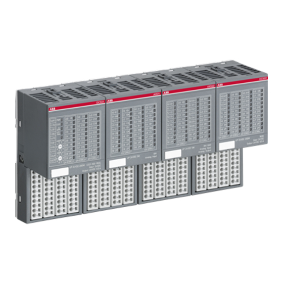
System Data S500, Overview
S500 system data, assortment
Use of the S500 I/O modules
Diagnosis LEDs
Mounting and disassembling the Terminal Units and the I/O modules
Mechanical dimensions S500
Switch-gear cabinet assembly
Connection system
Mechanical encoding
General wiring recommendations
Behaviour of the system in case of power supply interruptions and power recovery
Block diagrams, earthing concept
____________________________________________________________________________________________________________
V2
S500 Hardware
1-1
System Data
Page 1-3
1-4
1-5
1-13
1-17
1-19
1-20
1-24
1-26
1-26
1-26
S500 / Issued: 01.2007
Advertisement
Table of Contents

Related Manuals for ABB S500


Summary of Contents for ABB S500
- Page 1 System Data S500, Overview S500 system data, assortment Page 1-3 Use of the S500 I/O modules Diagnosis LEDs Mounting and disassembling the Terminal Units and the I/O modules 1-13 Mechanical dimensions S500 1-17 Switch-gear cabinet assembly 1-19 Connection system 1-20...
- Page 2 ____________________________________________________________________________________________________________ S500 Hardware System Data S500 / Issued: 01.2007...
-
Page 3: Table Of Contents
S500 System data The same system data as for the system AC500 apply to the system S500-FBP. Only additional details are therefore documented here. Assortment Parts of the S500-FBP system are • the FBP Interface Module DC505-FBP • digital I/O modules •... -
Page 4: Use Of The S500 I/O Modules
Use of the S500 I/O modules The S500 I/O modules either can be attached directly to an AC500 CPU (central expansion) or be operated by the FBP Interface Module DC505-FBP (decentralized expansion). CM572 CM577 PM581 DC532 DC532 DIN rail, earthed... -
Page 5: Diagnosis Leds
Diagnosis LEDs All S500 modules have LEDs for the display of operating statuses and error messages. They indicate: Status Color LED = ON LED = OFF LED flashes Input digital input yellow input = ON input = OFF analog input... - Page 6 Case A1 LEDs during initialization (I/O-Bus + FBP) Case A2 The module remains uninitialized, if errors occur LEDs after successful initialization (normal condition) Case A3 Figure: Initialization DC505-FBP without I/O modules attached ____________________________________________________________________________________________________________ S500 Hardware System Data S500 / Issued: 01.2007...
- Page 7 Case B2 LEDs during FBP initialization, number of I/O modules max. 7 Case B3 LEDs after successful initialization (normal condition) Case B4 Figure: Initialization DC505-FBP with I/O modules attached ____________________________________________________________________________________________________________ S500 Hardware System Data S500 / Issued: 01.2007...
- Page 8 Case C1 LEDs during initialization initialization of e.g. two modules successful, FBP, however, blocks the access by FBP-Conf_error, the red LED CONF flashes Case C2 Figure: Initialization with one I/O module missing ____________________________________________________________________________________________________________ S500 Hardware System Data S500 / Issued: 01.2007...
- Page 9 (instead of 3) successful, FBP, however, blocks the access by FBP-Conf_err, the red LED CONF flashes, details see the FBP user documentation Case D2 Figure: Initialization, if more I/O modules present than have been configured ____________________________________________________________________________________________________________ S500 Hardware System Data S500 / Issued: 01.2007...
- Page 10 UP is present at all modules, FBP is plugged An I/O bus error is sent to the fieldbus master, the I/O-Bus turns to the reset status or gets the replacement values Figure: Appearance of errors in running operation ____________________________________________________________________________________________________________ S500 Hardware 1-10 System Data S500 / Issued: 01.2007...
- Page 11 After that, an I/O module of an other type is inserted into the free place The status of the error message remains unchanged Figure: One module was removed and then replaced by a module of an other type ____________________________________________________________________________________________________________ S500 Hardware 1-11 System Data S500 / Issued: 01.2007...
- Page 12 Everything is still running, but an error message is sent to the fieldbus master Situation: A wrong parameter was sent to a module An error message is sent to the fieldbus master Figure: Displays in case of different errors ____________________________________________________________________________________________________________ S500 Hardware 1-12 System Data S500 / Issued: 01.2007...
-
Page 13: Mounting And Disassembling The Terminal Units And The I/O Modules
The FBP Terminal Unit is put on the DIN rail above and then snapped-in below. The disassembly is carried out in a reversed order. Figure: Disassembly of the FBP Terminal Unit (TU505 or TU506) ____________________________________________________________________________________________________________ S500 Hardware 1-13 System Data S500 / Issued: 01.2007... - Page 14 Figure: Maximum configuration (1 FBP Terminal Unit plus 7 I/O Terminal Units) Important: Up to 7 I/O modules can be used, of which up to 4 analog I/O modules are possible. ____________________________________________________________________________________________________________ S500 Hardware 1-14 System Data S500 / Issued: 01.2007...
- Page 15 A screwdriver is inserted in the indicated place to separate the Terminal Units. Step 4: Mount the modules DC532 Figure: Assembly of the modules Press the electronic module into the Terminal Unit until it locks in place. ____________________________________________________________________________________________________________ S500 Hardware 1-15 System Data S500 / Issued: 01.2007...
- Page 16 1 The Wall Mounting Accessory TA526 is snapped on the rear side of the Terminal Unit like a DIN rail. The arrow points to the right side. 2 Accessory for wall mounting inserted 3 Terminal Unit, fastened with screws ____________________________________________________________________________________________________________ S500 Hardware 1-16 System Data S500 / Issued: 01.2007...
-
Page 17: Mechanical Dimensions S500
Mechanical dimensions S500 57.7 (2.27) DC505 67.5 (2.66) 67.5 (2.66) Dimensions: 135 mm TU505/506 TU515/516/531/532 (5.31) inches Figure: Dimensions of the Terminal Units (front view) ____________________________________________________________________________________________________________ S500 Hardware 1-17 System Data S500 / Issued: 01.2007... - Page 18 Figure: Dimensions of Terminal Units and modules (lateral views) 4.9 (0.19) 40.3 57.7 (1.59) (2.27) 67.5 (2.66) (1.10) (1.10) 123.5 (4.86) Dimensions: 135 mm TB521-ETH (5.31) inches Figure: Dimensions of the AC500 CPU Terminal Base TB521-ETH (for comparison) ____________________________________________________________________________________________________________ S500 Hardware 1-18 System Data S500 / Issued: 01.2007...
-
Page 19: Switch-Gear Cabinet Assembly
Cable duct 20 mm minimum distance between the modules and the cable duct DC505 DC532 DC532 DIN rail, earted Mounting plate, earthed Figure: Installation of AC500/S500 modules in a switch-gear cabinet ____________________________________________________________________________________________________________ S500 Hardware 1-19 System Data S500 / Issued: 01.2007... -
Page 20: Connection System
2 (with the same cross section) flexible 0.08 mm² to 0.75 mm² 2 (with the same cross section) in flexible 0.25 mm² to 0.34 mm² wire end ferrule, without plastic sleeve ____________________________________________________________________________________________________________ S500 Hardware 1-20 System Data S500 / Issued: 01.2007... - Page 21 2 x 0.25 mm² or 2 x 0,5 mm² or 2 x 0,75 mm², with square cross-section of the wire-end ferrule also 2 x 1.0 mm² solid not intended flexible not intended ____________________________________________________________________________________________________________ S500 Hardware 1-21 System Data S500 / Issued: 01.2007...
- Page 22 Connect the wire to the spring terminal Opening Opening for screw- conductor driver Screwdriver Terminal Screwdriver open inserted Terminal Screwdriver closed Spring Figure: Connect the wire to the spring terminal (steps 1 to 3) ____________________________________________________________________________________________________________ S500 Hardware 1-22 System Data S500 / Issued: 01.2007...
- Page 23 Strip the wire for 7 mm (and put on wire end ferrule) Insert wire into the open terminal Remove the screwdriver Done Disconnect wire from the spring terminal Screwdriver Screwdriver Figure: Disconnect wire from the spring terminal (steps 1 to 3) ____________________________________________________________________________________________________________ S500 Hardware 1-23 System Data S500 / Issued: 01.2007...
-
Page 24: Mechanical Encoding
While erecting the screwdriver, insert it until the stop (requires a little strength), terminal is now open Remove wire from the open terminal Remove the screwdriver Done Mechanical encoding Pos. Figure: Possible positions for mechanical encoding (1 to 18) ____________________________________________________________________________________________________________ S500 Hardware 1-24 System Data S500 / Issued: 01.2007... - Page 25 Terminal Units (S500) and CPU Terminal Bases (AC500) have an mechanical coding which prevents that modules are inserted to wrong places. Otherwise • dangerous parasitic voltages could occur or • modules could be destroyed. The coding either makes it impossible to insert the module to the wrong place or blocks its electrical function (outputs are not activated).
-
Page 26: General Wiring Recommendations
Block diagrams, earthing concept Block diagram DC505-FBP, earthing concept The S500-FBP modules have to be included into the global earthing concept of the system. The following schematics will help you to understand the internal conception of the device. The electrical isolation of the device is realized as follow: •... - Page 27 There is no electrical isolation between the I/O channels of an I/O module. FBP Terminal Unit TU505/TU506 I/O-Bus DC505-FBP Digital I/O rail I/O-Bus CH-ERRx Power supply Power supply Inputs Inputs/outputs +24V Figure: Blocks diagram DC505-FBP with FBP, earthing concept ____________________________________________________________________________________________________________ S500 Hardware 1-27 System Data S500 / Issued: 01.2007...
- Page 28 Block diagram of the digital I/O modules, earthing concept I/O Terminal Unit TU515/TU516 I/O-Bus DC532/DI524 I/O-Bus Digital rail I/O interface CH-ERRx Power supply I/Os Inputs/outputs +24V Figure: Block diagram of the digital I/O modules, earthing concept ____________________________________________________________________________________________________________ S500 Hardware 1-28 System Data S500 / Issued: 01.2007...
- Page 29 I/O-Bus rail CH-ERRx Inputs Outputs Power supply +– +– +– +– I+ I– I+ I– O+ O– O+ O– +24V Figure: Block diagram of the analog I/O modules, earthing concept ____________________________________________________________________________________________________________ S500 Hardware 1-29 System Data S500 / Issued: 01.2007...
- Page 30 ____________________________________________________________________________________________________________ S500 Hardware 1-30 System Data S500 / Issued: 01.2007...