Siemens CM 1542-5 Manual
Profibus interface
Hide thumbs
Also See for CM 1542-5:
- Operating instructions manual (52 pages) ,
- Operating instructions manual (68 pages)
Table of Contents
Advertisement
CM 1542-5
SIMATIC NET
S7-1500 - PROFIBUS
CM 1542-5
Manual
11/2014
C79000-G8976-C290-02
___________________
Preface
___________________
Guide to the documentation
___________________
Product overview
___________________
Functional characteristics
___________________
Requirements for use
___________________
Connecting up /
commissioning
Interrupts, diagnostics
messages, error and system
alarms
___________________
Technical specifications
___________________
Approvals
1
2
3
4
5
6
7
8
Advertisement
Table of Contents

Related Manuals for Siemens CM 1542-5


Summary of Contents for Siemens CM 1542-5
- Page 1 ___________________ CM 1542-5 Preface ___________________ Guide to the documentation ___________________ SIMATIC NET Product overview ___________________ Functional characteristics S7-1500 - PROFIBUS CM 1542-5 ___________________ Requirements for use ___________________ Connecting up / commissioning Manual Interrupts, diagnostics messages, error and system alarms ___________________...
- Page 2 Note the following: WARNING Siemens products may only be used for the applications described in the catalog and in the relevant technical documentation. If products and components from other manufacturers are used, these must be recommended or approved by Siemens. Proper transport, storage, installation, assembly, commissioning, operation and maintenance are required to ensure that the products operate safely and without any problems.
-
Page 3: Preface
All functions that go beyond the system are described in the system manual. With the information in this manual and the system manual, you will be able to commission the CM 1542-5 communications module. See also Guide to the documentation (Page 7) Conventions... - Page 4 Siemens recommends strongly that you regularly check for product updates. For the secure operation of Siemens products and solutions, it is necessary to take suitable preventive action (e.g. cell protection concept) and integrate each component into a holistic, state-of-the-art industrial security concept.
-
Page 5: Table Of Contents
Connecting up / commissioning ......................17 Important notes on using the device ..................17 Installing and commissioning the CM 1542-5 ................. 19 Replacing a module without a programming device ............... 21 Mode of the CPU - effect on the CM ..................22 Interrupts, diagnostics messages, error and system alarms .............. - Page 6 Table of contents CM 1542-5 Manual, 11/2014, C79000-G8976-C290-02...
-
Page 7: Guide To The Documentation
Overview of the documentation on communication with S7-1500 The following table lists additional documents, which supplement this description of CM 1542-5 and are available in the Internet. Table 1- 1 Documentation for the CM 1542-5 Topic... - Page 8 The "Version History/Current Downloads for SIMATIC NET S7 CPs (PROFIBUS)" provides information on all CPs available up to now for SIMATIC S7 (PROFIBUS). An up-to-date version of this document can be found on the Internet (http://support.automation.siemens.com/WW/view/en/9836605) CM 1542-5 Manual, 11/2014, C79000-G8976-C290-02...
-
Page 9: Product Overview
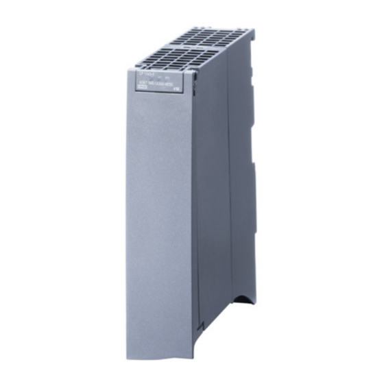
Communications module CM 1542-5 for SIMATIC S7-1500 on PROFIBUS DP. View of the module ① LEDs ② Type plate ③ PROFIBUS interface: 1 x 9-pin D-sub female connector (RS-485) Figure 2-1 View of the CM 1542-5 with closed (left) and open (right) front cover CM 1542-5 Manual, 11/2014, C79000-G8976-C290-02... - Page 10 – DP master mode for Siemens DP slaves – Direct data exchange (DP slave to DP slave) As a DP master, the CM 1542-5 is capable of enabling direct data exchange for "its" DP slaves. – SYNC / FREEZE The outputs or inputs can be synchronized by the user program using system function DPSYNC_FR.
-
Page 11: Further Functions
DP slaves can be activated and deactivated by the user program using system function D_ACT_DP. Diagnostics requests As a DP master (class 1), the CM 1542-5 supports diagnostics requests of a DP master (class 2). Getting the bus topology in a DP master system The CM 1542-5 operating as DP master supports the measurement of the PROFIBUS bus topology in a DP master system using a diagnostics repeater (DP slave). - Page 12 Product overview 2.2 Further functions CM 1542-5 Manual, 11/2014, C79000-G8976-C290-02...
-
Page 13: Functional Characteristics
Max. size of the output area of all DP slaves 8 Kbytes Maximum number of inputs per DP slave 244 bytes Maximum number of outputs per DP slave 244 bytes Max. size of the consistent area for a module 128 bytes CM 1542-5 Manual, 11/2014, C79000-G8976-C290-02... -
Page 14: Characteristics Of S7 Communication
Functional characteristics 3.3 Characteristics of S7 communication Diagnostics requests As a DP master (class 1), the CM 1542-5 supports diagnostics requests of a DP master (class 2). DP startup behavior Note Increasing the default value for startup parameters - configuration of the CPU In some situations, it is necessary to increase the default value for the startup parameter "Parameter assignment time for the distributed I/O"... -
Page 15: Requirements For Use
Project engineering Configuration and downloading the configuration data When the configuration data is downloaded to the CPU, the CM 1542-5 is supplied with the relevant information. The configuration data can be downloaded to the CPU via PROFIBUS or any PROFINET interface of the S7-1500 station. - Page 16 ● Instruction WRREC "Write data record to a DP slave" corresponds to SFC58 in terms of function ● Instruction RALRM "Read interrupt information from a DP slave" - call in an interrupt OB PNO: PROFIBUS Users Organization See also 8797900 (http://support.automation.siemens.com/WW/view/en/8797900) CM 1542-5 Manual, 11/2014, C79000-G8976-C290-02...
-
Page 17: Connecting Up / Commissioning
General notices on use in hazardous areas WARNING Risk of explosion when connecting or disconnecting the device EXPLOSION HAZARD DO NOT CONNECT OR DISCONNECT EQUIPMENT WHEN A FLAMMABLE OR COMBUSTIBLE ATMOSPHERE IS PRESENT. CM 1542-5 Manual, 11/2014, C79000-G8976-C290-02... - Page 18 General notices on use in hazardous areas according to ATEX WARNING Requirements for the cabinet/enclosure To comply with EU Directive 94/9 (ATEX95), this enclosure must meet the requirements of at least IP54 in compliance with EN 60529. CM 1542-5 Manual, 11/2014, C79000-G8976-C290-02...
-
Page 19: Installing And Commissioning The Cm 1542-5
Connecting up / commissioning 5.2 Installing and commissioning the CM 1542-5 WARNING Suitable cables for temperatures in excess of 70 °C If the cable or conduit entry point exceeds 70°C or the branching point of conductors exceeds 80°C, special precautions must be taken. If the device is operated at ambient temperatures above 50°C, the permitted temperature range of the selected cable must be... - Page 20 Connecting up / commissioning 5.2 Installing and commissioning the CM 1542-5 Procedure for installation and commissioning Step Execution Notes and explanations When installing and connecting up, keep to the procedures described for installing I/O modules in the system manual "S7-1500 Automation Sys- tem".
-
Page 21: Replacing A Module Without A Programming Device
General procedure The configuration data of the CM is stored on the CPU. This means that this module can be replaced by a module of the same type (identical article number) without using a PG. CM 1542-5 Manual, 11/2014, C79000-G8976-C290-02... -
Page 22: Mode Of The Cpu - Effect On The Cm
● The following functions remain enabled: – The configuration and diagnostics of the CM (system connections for configuration, diagnostics, and PG channel routing are retained); – S7 routing function – Time-of-day synchronization CM 1542-5 Manual, 11/2014, C79000-G8976-C290-02... -
Page 23: Interrupts, Diagnostics Messages, Error And System Alarms
Interrupts, diagnostics messages, error and system alarms The status and error displays of the CM 1542-5 are described below. You can find additional information on "Interrupts" in the STEP 7 online help. You can find additional information on "Diagnostics" and "System alarms" in the System diagnostics (http://support.automation.siemens.com/WW/view/en/59192926) function... - Page 24 Interrupts, diagnostics messages, error and system alarms 6.1 Status and error display of the CM Meaning of the LED displays The CM 1542-5 has 3 LEDs to display the current operating status and the diagnostics status and these have the following meanings: (one-color LED: green) •...
-
Page 25: Diagnostics Options
The diagnostics data is transferred as a diagnostics interrupt. Diagnostics interrupts must be acknowledged by the DP master. Supported diagnostics functions The CM 1542-5 supports the following blocks of DP diagnostics: ● Standard diagnostics (6 bytes) ● Identifier-related diagnostics (2 to 17 bytes), depending on the number of configured transfer areas ●... - Page 26 Table 6- 2 Overview of device-specific diagnostics of the CM with DP-V1 slaves Device-specific diagnostics Byte Meaning Header Variant Variant Interrupt type Status type Slot number Variant Variant Interrupt specifier Status specifier 4...62 Module-specific diagnostics data CM 1542-5 Manual, 11/2014, C79000-G8976-C290-02...
-
Page 27: Standard Diagnostics
This bit is set by the DP master 1 (the slave sets this bit permanently to 0). If the bit is set, the diagnostic bits have the state of the last diagnostics alarm or the initial value. CM 1542-5 Manual, 11/2014, C79000-G8976-C290-02... - Page 28 The vendor ID ("Ident_Number") for the DP slave type is entered in bytes 4 and 5. This identifier can be used to identify the slave. The more significant part of the value is in byte 5. CM 1542-5 Manual, 11/2014, C79000-G8976-C290-02...
-
Page 29: Device-Specific Diagnostics In Dp-V1
Hardware interrupt Pull interrupt Plug interrupt Status interrupt Update interrupt 7...31 - reserved - 32...126 Vendor-specific - reserved - If status interrupts are received in quick succession, older status interrupts may be overwritten by newer interrupts. CM 1542-5 Manual, 11/2014, C79000-G8976-C290-02... - Page 30 The slot generates an interrupt due to an error. Interrupt disappears, slot OK The slot generates the interrupt and indicates that it has no further errors. Interrupt disappears, slot still disrupted The slot generates an interrupt and indicates that it has further errors. CM 1542-5 Manual, 11/2014, C79000-G8976-C290-02...
- Page 31 The status bits are coded as follows: Table 6- 11 Meaning of the values of the status bits Value Meaning Data valid Data invalid - error (for example short-circuit) Data invalid - wrong module Data invalid - no module plugged in CM 1542-5 Manual, 11/2014, C79000-G8976-C290-02...
-
Page 32: Dp Diagnostics Frames When The Cpu Is In Stop
All diagnostics frames from DPV0 standard slaves and all DP interrupt frames from DP- S7/DPV1 standard slaves arriving when the CPU is in STOP are forwarded to the CPU. During module startup, the diagnostics frames must then be evaluated by a suitable user program. CM 1542-5 Manual, 11/2014, C79000-G8976-C290-02... -
Page 33: Technical Specifications
Note the information in the System description of SIMATIC S7-1500 (Page 7). In addition to the information in the system description, the following technical specifications apply to the module. 6GK7 542-5DX00-0XE0 Product type name CM 1542-5 Connection to PROFIBUS 1 x PROFIBUS interface Number •... - Page 34 Technical specifications CM 1542-5 Manual, 11/2014, C79000-G8976-C290-02...
-
Page 35: Approvals
Certificates for shipbuilding and national approvals The device certificates for shipbuilding and special national approvals can be found on the pages of Siemens Automation Customer Support on the Internet (http://support.automation.siemens.com/WW/news/en/10805878) Under this entry, go to the required product and select the following settings: "Entry list" tab >... - Page 36 D-90327 Nürnberg You will find the EC Declaration of Conformity at the following address / under the following entry ID on the Internet (http://support.automation.siemens.com/WW/view/en/16689636) EMC directive The SIMATIC NET S7 CPs listed above are designed for use in an industrial environment.
- Page 37 ● ANSI ISA 12.12.01, CSA C22.2 No. 213-M1987 (Hazardous Location) ● CSA–213 (Hazardous Location) APPROVED for Use in ● Cl. 1, Div. 2, GP. A, B, C, D T3...T6 ● Cl. 1, Zone 2, GP. IIC T3...T6 CM 1542-5 Manual, 11/2014, C79000-G8976-C290-02...
- Page 38 WARNING - EXPLOSION HAZARD: DO NOT DISCONNECT EQUIPMENT WHEN A FLAMMABLE OR COMBUSTIBLE ATMOSPHERE IS PRESENT. When used in hazardous locations (division 2 or zone 2), the device must be installed in an enclosure. CM 1542-5 Manual, 11/2014, C79000-G8976-C290-02...
-
Page 39: Index
DPRD_DAT, 16 DP master DPSYC_FR, 15 Operation as, 10 DPWR_DAT, 16 DP master (class 1), 10, 11 GETIO, 15 DP master mode, 22 GETIO_PART, 16, 16 DP masters (class 2), 11 RALARM, 16 RALRM, 16 CM 1542-5 Manual, 11/2014, C79000-G8976-C290-02... - Page 40 Index RDREC, 15, 16 Safety extra low voltage, 17 SETIO, 16 Safety notices, 17 WRREC, 15, 16 Siemens DP slave, 10 Interrupts, 23 SIMATIC NET glossary, 4 SIMATIC NET Manual Collection, 8 Startup parameters, 14 Status and error displays, 23...