Table of Contents
Advertisement
(TM)
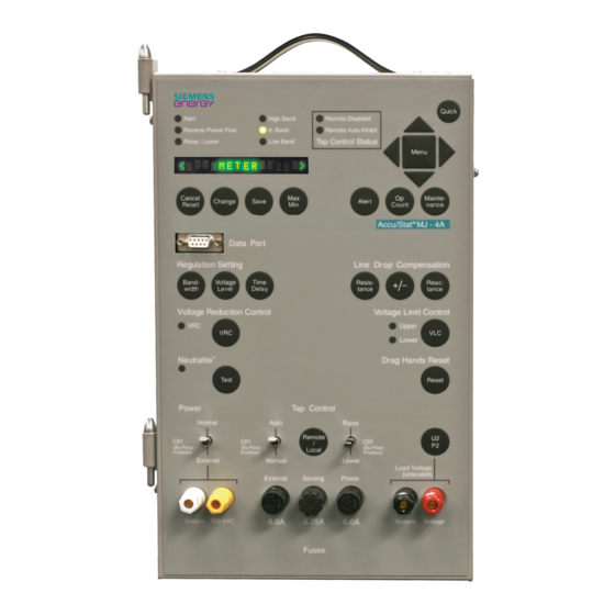
MJ-4A
Control Panel
Installation and Operations Manual
Manual No. 21-115-527-023 rev02
and MJ-4B
High Band
Alert
Reverse Power Flow
In Band
Low Band
Raise/ Lower
Cancel
Change
Save
Reset
Data Port
Regulation Setting
Band
-
Time
Voltage
Delay
width
Level
Voltage Reduction Control
VRC
Neutralite
Test
Power
Auto
Normal
Off
Off
(
By pass
(
By pass
)
Position
)
Position
Manual
External
External
Ground 120 VAC
6.0A
(TM)
Voltage Regulator
Remote Disabled
Remote Auto Inhibit
Tap Control Status
Max
Alert
Count
Min
Accu/Stat MJ – 4A
Line Drop Compensation
Resis
-
+/-
tance
Voltage Limit Control
Tap Control
Raise
Off
Remote
(
By pass
/
Local
)
Position
Lower
Load Voltage
( unscaled )
Sensing
Power
0.75A
6.0A
Ground Voltage
Fuses
Quick
Menu
Op
Mainte
-
nance
Reac
-
tance
VLC
Drag Hands
Reset
U2
P2
Siemens Energy, Inc.
Advertisement
Table of Contents
Troubleshooting

Related Manuals for Siemens MJ-4A


Summary of Contents for Siemens MJ-4A
- Page 1 Raise Normal Remote By pass By pass By pass Local Position Position Position Manual Lower External Load Voltage ( unscaled ) External Sensing Power Ground 120 VAC 6.0A 0.75A 6.0A Ground Voltage Fuses Manual No. 21-115-527-023 rev02 Siemens Energy, Inc.
- Page 2 It does not relieve the user of responsibility to use sound prac- tices in application, installation, operation, and maintenance of the equipment pur- chased. Siemens reserves the right to make changes at any time without notice of obligations. Should a conflict arise between the general information contained in this publication and the contents of drawings or supplementary material, or both, the latter shall take precedence.
-
Page 3: Table Of Contents
1 Introduction........1 5 Reading and Interpreting MJ-4A & MJ-4B Control Panel Data ....39 About This Manual ....... 1 Features of the MJ-4A & MJ-4B Control Source and Load Definitions ..... 39 Panels ............ 1 P2 Voltage Calculation......39 Mounting on Siemens Regulators ..2 Meter Data—the <METER>... - Page 4 ............70 G Menu Structure Quick Reference..72 H MJ-4A & MJ-4B Firmware Versions............... 74 Terminal Strip Wiring.......75 J MJ-4A & MJ-4B Jumpers and Battery Replacement........76 MJ-4A & MJ-4B Jumpers ....76 Battery Replacement......77 K Terminal Strip Connections.....78 L MJ-4A &...
-
Page 5: Introduction
MJ-4 is a Voltage Regulator Control Panel, MJ-4 software version 4.10 which is a members of the Siemens Accu/Stat® series of Features of the MJ-4A & MJ-4B digital controls, designed for use with many regulators and load tap changer models. -
Page 6: Mounting On Siemens Regulators
Support Documentation Communications The MJ-4 panel provide local communications via the In addition to this manual, Siemens provides a number of front-panel data port, and supports remote communica- supporting documents that provide details about the use tions with the MJ-4 Communications Module. -
Page 7: Using The Mj-4A & Mj-4B Operator Panel And Controls
Using the MJ-4A & MJ-4B Operator Panel and Controls 2 Using the MJ-4A & MJ-4B Operator Panel and Controls Quick Key Quick Menu Selection High Band Remote Disabled Alert Indicators Scroll Keys Reverse Power Flow In Band Remote Auto Inhibit... - Page 8 Using the MJ-4A & MJ-4B Operator Panel and Controls Quick Key Quick Menu Selection High Band Remote Disabled Alert Indicators Scroll Keys Reverse Power Flow In Band Remote Auto Inhibit Tap Control Status Raise/Lower Low Band Menu Alert Status Fast Path Key...
-
Page 9: Introduction To The Front Panel
Press this key once to return to the top of the current Menu. To return to the start of all Menus from any position In the bottom third, the MJ-4A Panel has mode and raise in any Menu press this key twice. - Page 10 Using the MJ-4A & MJ-4B Operator Panel and Controls To change an item: Max/Min data items are displayed for a short period of time, after which the display returns to the current value. View the item using either the menu selection keys or The length of this period can be selected by the operator.
- Page 11 Using the MJ-4A & MJ-4B Operator Panel and Controls Time Delay Key Press this key to view the contents of the <ALERTS> Menu. If any Alert messages are active, press this key repeatedly to step through them in order of priority. If no Alerts are active, the message “No Active Alerts”...
-
Page 12: Indicators
P2 out is set to Toggle. Neutralite Test Key The Raise and Lower keys are present in the MJ-4B Panel. The MJ-4A panel has discrete switch for the same func- tionality. T e s t While Automatic tap operations are disabled, the Raise and Lower keys are active. - Page 13 Using the MJ-4A & MJ-4B Operator Panel and Controls When the real component of load current drops below 1% Band Indicator Status Table 2.2 of rated current, the RPF indicator continues to display its Power Flow Band Indicator Status previous state.
-
Page 14: Switches
Neutralite Test key is pressed and held. the tap changer motor. Switches • This push button is common for both the MJ-4A & MJ-4B Panels. Power Switch This three-position switch selects the power source for Raise and Lower Switches / Push buttons the MJ-4 Control Panel. -
Page 15: Binding Posts
Using the MJ-4A & MJ-4B Operator Panel and Controls Switch Positions for Bypassing Cal” or “P2 Cal” in the <DIAGNOSTICS> menu defines the voltage (U2 or P2) you can read at these binding posts. The front panel switches must be in the following posi- The binding posts are dual banana-style receptacles. -
Page 16: Terminal Strip Connections
Using the MJ-4A & MJ-4B Operator Panel and Controls Terminal Strip Connections Complete descriptions of all terminal contacts are provided in Appendix K. Terminal strips are located on the lower back side of the MJ-4 Control Panel. These terminals can be used to pro- vide access to certain microprocessor and other control functions. - Page 17 Using the MJ-4A & MJ-4B Operator Panel and Controls Power and Motor Control Terminal Contacts A simplified schematic drawing of the power and motor control terminal connections is shown in Figure 2.3 below Power Switch Connections for Connections for External Motor Power...
-
Page 18: Local Data Port
Using the MJ-4A & MJ-4B Operator Panel and Controls Local Data Port The Local Data Port on the front panel supports connec- Jumpered for DTE tion to a PC or other communications device. It transfers data in either direction: the MJ-4 Control Panel can provide... -
Page 19: Viewing And Changing Mj-4A & Mj-4B Data Items
Viewing and Changing MJ-4A & MJ-4B Data Items 3 Viewing and Changing MJ-4A & MJ-4B Data Items The MJ-4 Control Panel stores a considerable amount of Setup Menus define the environment. In general, data. Some of the data items are setpoints used to control these Menus are only used at installation. -
Page 20: Changing Data Items
Viewing and Changing MJ-4A & MJ-4B Data Items Changing Data Items If you are not sure where you are in the Menu structure, press the Menu key once to return to the top of that To change data, you must first view it, as described above. -
Page 21: Using The Fast-Path Keys To View/Change Data Items
Viewing and Changing MJ-4A & MJ-4B Data Items Using the Fast-Path Keys to View/ Changing Alpha or Numeric Settings Change Data Items The process of changing alpha or numeric settings is simi- lar to that of changing configuration parameters, except... -
Page 22: Setting Up The Mj-4A & Mj-4B Control Panel
Setting Up the MJ-4A & MJ-4B Control Panel 4 Setting Up the MJ-4A & MJ-4B Control Panel Setup—Overview Communications Definition In this step, use the <COMMUNICATIONS> Menu to MJ-4 Control Panel setup procedures allow you to custom- define communications parameters (baud rate, unit ize the control panel to your needs and to the environment address, etc.). -
Page 23: Setup For Retrofit Panels
If you are retrofitting either a G. E. or Cooper regulator for Figures 4.1 to 4.4 show typical Siemens regulator name- use with the Siemens MJ-4 Control Panel, please refer to plates. Refer to these figures for information that can be the respective Application Note. - Page 24 TapChngr SIEMENS I FullLoad 328 Type STRAIGHT CTratio 400:0.2 Utility Pol NORM (E2 to right of U Terminals) U2PT: 7620:124 P2PT: 7620:124 Figure 4.2 Typical Siemens Regulator Nameplate for ANSI A (Straight) regulator without a Load Side PT. Siemens Energy, Inc.
- Page 25 M a d e i n U S A J a c k s o n , M S 21-115905-002 Figure 4.4 Typical Siemens Regulator Nameplate for ANSI Type B (Inverted) Regulator Note: Items are not highlighted on actual nameplate. Siemens Energy, Inc.
- Page 26 Setting Up the MJ-4A & MJ-4B Control Panel The <CONFIGURE> Menu 4.3.5 Utility Pol (Utility Polarity) The Utility Pol data item allows you to correct for polarity 4.3.1 TapChngr (Tap Changer Type) differences between the CT winding and the Utility (Ter- tiary) winding.
- Page 27 Setting Up the MJ-4A & MJ-4B Control Panel Many regulators are built with transformer turns ratios that 4.3.11 Power Flow Modes do not provide the exact basis voltage (115, 120, or 125 V) The Power Flow Mode data item allows you to specify to the controller.
- Page 28 Setting Up the MJ-4A & MJ-4B Control Panel The <ADV CONFIGURE> Menu ondary voltage to 115, 120, or 125 volts. See U2 PT and P2 PT data items above. Also see Section 5.3.2. 4.3.17 Meter Volts (Meter Scaling) 4.3.13 NeutOvRun (Neutral Overrun)
- Page 29 Setting Up the MJ-4A & MJ-4B Control Panel Date periods and specify the number of subperiods as a num- ber between 1 and 99. The Date data item allows you to set the real-time calen- dar. Use the format selected in the Format item. If the for-...
- Page 30 PT. For regulators with voltages on both tap change and waits for it to do so. Contact your Siemens the Load and Source bushing, the P2 calculation may be...
- Page 31 Setting Up the MJ-4A & MJ-4B Control Panel 4.3.40 Current Bias The user may choose None, Fwd, Rev or NeutT for current flow modes. The Bias percent is selected from the follow- ing Bias % data item. 4.3.41 Bias Percent The minimum Bias percent is 0% and the maximum is 10%.
-
Page 32: Setting Control Levels- The
Setting Up the MJ-4A & MJ-4B Control Panel Setting Control Levels— MJ-4 Control Panel when operating in Automatic Mode. Variables in the <REGULATOR> Menu are summarized in the <REGULATOR> Menu Table 4.3 and described in detail in the following sections.Menu - Page 33 Setting Up the MJ-4A & MJ-4B Control Panel 4.4.1 Regulator Setpoints Time Delay Setpoint Regulator setpoints define the operating limits for Auto- The Time Delay setpoint defines the amount of time the matic mode operation. Two sets of limits are maintained: controller will wait before commanding a tap change.
- Page 34 Setting Up the MJ-4A & MJ-4B Control Panel VRC Mode MJ-3A Mode (“Pulsed” Input) This data item defines the VRC mode of operation. Select This mode simulates MJ-3A VRC; it uses only one exter- the desired mode, using the VRC Mode data item. Four nal contact(VRC1).
-
Page 35: Activating Data Logging- The
Setting Up the MJ-4A & MJ-4B Control Panel · · Activating Data Logging— AutoVRCn% (rated current). the <LOG SETUP> Menu Example 1 The MJ-4 Control Panel can record status information that AutoVRC1%I = 60%; AutoVRCset1 = 3%. will help reconstruct past occurrences. Two logs are main- tained: an Event Log, and an Interval Log.Menu -
Page 36: Password Security Protection- The
Setting Up the MJ-4A & MJ-4B Control Panel Password Security Protection— Power Factor, Power (KW, KVAR, KVA), Tap position, Vsrc the <PASSWORD> Menu To activate Events Logging, view Log Event; then select MJ-4 security allows unrestricted read access to any data ON.Menu - Page 37 Setting Up the MJ-4A & MJ-4B Control Panel trator. This person would be responsible for establishing 4.6.2 The <PASSWORD> Menu the password protection scheme and for making changes The <PASSWORD> Menu serves three purposes: to the passwords as necessary; He/she would be the only individual requiring knowledge of the “System Key.
- Page 38 Setting Up the MJ-4A & MJ-4B Control Panel 4.6.3 Setting Up the MJ-4A & MJ-4B Security In addition to defining passwords for a given level, you must also enable that level before password checking System. takes place. When password checking is enabled for a...
-
Page 39: Communications Definition- The
Setting Up the MJ-4A & MJ-4B Control Panel Communications Definition— Level 1 password or a Level 2 password. Data items con- tained in Menus that are password protected by Level 2 the <COMMUNICATIONS> Menu passwords can only be changed or reset after you enter the Level 2 password for that Menu.Menu - Page 40 Setting Up the MJ-4A & MJ-4B Control Panel The “Comm Addr” screen shows the communications address for the MJ-4 unit. For the Data Port, the usable Table 4.10 Communications Module Configuration Items address ranges are listed in Table 4.9 below. Note that the MJ-4 is device type “1”...
-
Page 41: Regulator Maintenance- The
Setting Up the MJ-4A & MJ-4B Control Panel Regulator Maintenance— Hardware Configuration— the <MAINTENANCE> Menu the <DIAGNOSTICS> Menu The information contained within the <MAINTENANCE> The <DIAGNOSTICS> Menu includes the MJ-4 hardware menu should be used for information purposes only. All...Menu -
Page 42: Setting Up The Quick Key
Setting Up the MJ-4A & MJ-4B Control Panel 4.10 Setting up the Quick Key The Quick Key provides access to the customizable Quick List. The Quick List can be used to step through a series of up to 15 user-set menu items. The Quick List allows creation of a custom menu with the minimal amount of effort. -
Page 43: Reading And Interpreting Mj-4A & Mj-4B Control Panel Data
Reading and Interpreting MJ-4A & MJ-4B Control Panel Data 5 Reading and Interpreting MJ-4A & MJ-4B Control Panel Data The MJ-4 Control Panel microprocessor maintains a con- “L ” bushing voltage is the “Load voltage. With power siderable amount operational information—both... - Page 44 Reading and Interpreting MJ-4A & MJ-4B Control Panel Data displayed. Pressing the key displays the last metered power flow conditions, load current includes regulator data item. An example for displaying min/max time and excitation current which could be approximately 10% date stamps is shown below: higher or lower than actual load current.
-
Page 45: Demand Data- The
Reading and Interpreting MJ-4A & MJ-4B Control Panel Data kWhr F and kWhr R (Forward and Reverse Real Energy) Demand Data Items Table 5.4 The Forward and Reverse kWhr data items display Kilo- Fdmd Vld Load Voltage demand watt Hour values. They are accumulated separately for for-...Menus -
Page 46: Interval Log - The
Reading and Interpreting MJ-4A & MJ-4B Control Panel Data To access log data, view the <EVENT LOG> Menu with Table 5.6 describes the data that is logged at the conclu- the Menu Selection keys; then use the keys to sion of each interval.Menu -
Page 47: Operation Counter Data - The
Reading and Interpreting MJ-4A & MJ-4B Control Panel Data Operation Counter Data - Dead Reckoning for Siemens Regulators the <COUNTERS> Menu The control program keeps track of the regulator tap posi- tion by means of a “dead reckoning” procedure, analo- Operation counters record the stepping operations of the gous to navigational dead reckoning.Menu -
Page 48: Alerts-The
Reading and Interpreting MJ-4A & MJ-4B Control Panel Data Alerts—the <Alert> Menu If the Alert name is flashing, acknowledgment is required. Alerts represent exception conditions. A Alert condition 5.8.2 Acknowledging an Alert may be presently active, or it may have been active at To acknowledge the Alert, press the Cancel/Reset key.Menu -
Page 49: Harmonics Data- The
Reading and Interpreting MJ-4A & MJ-4B Control Panel Data Harmonics Data— 5.10 Local Data Port— the <HARMONICS> Menu the <COMMUNICATIONS> Menu Harmonics data are calculated for load voltage, source The <COMMUNICATIONS> Menu contains Local Data voltage, and load current. The <HARMONICS> Menu Port status.Menu -
Page 50: Mj-4A & Mj-4B Control Panel Automatic Mode
When the time period you may need when deciding between the various options has elapsed, if the MJ-4A Control Panel has Remote Auto described in Chapter 4 (Setting Up the MJ-4 Control Panel) Inhibit disabled, it resumes its normal automatic control and Chapter 5 (Reading and Interpreting MJ-4 Control operations. -
Page 51: Overview Of Automatic Control
In addition, the remote operator can change settings and remotely operate the control pro- Table 6.1 summarizes the four operating modes. gram. Table 6.1 Summary of Control Mode Operation MJ-4A and MJ-4B Switch Positions Manual Automatic Remote Control Enabled 1. -
Page 52: Voltage Sensing And Correction
MJ-4 senses the reversal and adjusts its operation accordingly. When power flow direction changes, the Software Voltage Measurement Correction MJ-4A & MJ-4B control algorithm takes the following fac- tors into account: The monitored output voltage is scaled appropriately to the nominal basis voltage in two steps. - Page 53 MJ-4A & MJ-4B Control Panel Automatic Mode Reverse power flow is indicated when the real power is voltage from the “L ” Bushing voltage and the knowl- negative and the real component of current is greater than edge of the tap position) to determine load voltage 1% of the full scale current.
- Page 54 MJ-4A & MJ-4B Control Panel Automatic Mode 6.5.4 Power Flow Modes Idle Reverse, and Co-generation. Your selection of one of these determines which algorithm the control program The MJ-4 supports six Power Flow Modes: Forward uses under reverse power flow conditions.
- Page 55 MJ-4A & MJ-4B Control Panel Automatic Mode F LOCK (Forward Locked Mode) R LOCK (Reverse Locked Mode) This mode of operation is intended for use on systems This mode of operation is intended for use on systems where reverse power flow is not anticipated. Tap changes where forward power flow is not anticipated.
- Page 56 MJ-4A & MJ-4B Control Panel Automatic Mode BI-DIR (Bi-directional mode) IDLE R (Idle Reverse) This mode of operation is intended for use on systems This mode of operation is intended for use on systems where reverse power flow is anticipated and voltage regu- where reverse power flow is an abnormal situation.
- Page 57 MJ-4A & MJ-4B Control Panel Automatic Mode NEUT R (Neutral Reverse) CO-GEN (Co-generation) This mode of operation is intended for use on systems This mode of operation is for use on systems where where reverse power flow is an abnormal situation.
-
Page 58: Software For Communicating With The Mj-4A & Mj-4B Control Panel
Software for Communicating with the MJ-4A & MJ-4B Control Panel 7 Software for Communicating with the MJ-4A & MJ-4B Control Panel Communications Software Uploading New MJ-4A & MJ-4B Software Siemens has developed a Windows-based communica- tions software application called MJXplorer. All configura-... -
Page 59: Mj-4A & Mj-4B Control Panel Basic Troubleshooting
MJ-4 failure. Verify the MJ-4 can automatically raise and lower tap position. Self Test Fault This alert indicates a failure of one or more MJ-4 self tests. Consult your Siemens representative for instructions. Siemens Energy, Inc. -
Page 60: Troubleshooting Based On Alert
MJ-4A & MJ-4B Control Panel Basic Troubleshooting Troubleshooting Based on Alert To check C/C2 Medium calibration, apply a nominal 80 mA AC current at C2/E1 and verify that “C/C2med” reads Messages within ± 0.5 mA of the applied value (as displayed on external Ammeter connected at C/C2.) -
Page 61: Mj-4A & Mj-4B Self Testing
MJ-4A & MJ-4B Control Panel Basic Troubleshooting Note: If password protection is in effect, you must Repeat the above procedure for C/C2 Medium and C/C2 enter the password to enable calibration. The High. After calibration, replace J1 and Terminal Strip default password for the <DIAGNOSTICS>... -
Page 62: A Specifications
Metering accuracy*: ±0.5% over the -40°C to +85°C oper- ating range. Operating: -40°C to +85°C Storage: -40°C to +85°C * Basic accuracy of the MJ-4A & MJ-4B (excludes Poten- tial Transformer or Current Transformer errors). Humidity Electrical transient immunity Operating: Relative humidity of 5% to 95% non-condens- The MJ-4A &... -
Page 63: B Physical Installation On Siemens Regulators
Switch Settings for MJ-4A (See Chapter 2) Note 2: The control being replaced may incorporate a As you prepare to install the MJ-4A Control Panel, the fol- jumper between the P2 and U2 terminals on the female lowing switch settings should be observed: (stationary) portion of the PDS. - Page 64 It is strongly recommended that MJ-4 controller repair, testing, Terminal Strip Connector and calibration be performed only by Siemens authorized repair facilities. External devices are wired to a terminal strip connector at the back of the MJ-4 Control Panel. See Appendix K for pin-outs and signal descriptions.
-
Page 65: C Regulator Control Diagrams
Appendix C: Regulator Control Diagrams C Regulator Control Diagrams Typical Control Diagrams - For Sample Reference Only ANSI Type ‘ A ’ (Straight) Regulator Control Diagram Figure C.1 Siemens Energy, Inc. - Page 66 Appendix C Regulator Control Diagrams ANSI Type ‘B’ (Inverted) Regulator Control Diagram Figure C.2 Siemens Energy, Inc.
-
Page 67: D Menu Parameters
Reactance Setting = 6.67 x 3 x 0.692 = 14V Using knowledge of the distribution feeder and the tables below, establish the conductor resistance and reactance per mile of feeder. EXAMPLE: Conductor 4/0 ACSR, Regular Flat Spacing at 24 inches. Siemens Energy, Inc. - Page 68 You may also download this application from enter the system values and the application automatically the Siemens web site (see Section 1.8). After arriving at calculates the resistive and reactive components for you. the website, select Products, and then the Voltage Reg- Enter these values in the <REGULATOR>...
-
Page 69: Configure> Menu: Transformer Polarity
(ANSI type A) without forced air cooling the Regulator nameplate. The Utility transformer polarity for Single-Phase Straight Design regulators can be determined from the regulator nameplate schematic diagram. The Utility winding taps are labeled Un -- Ux, E2. Siemens Energy, Inc. - Page 70 U15 to Volts 14400 P3 - 120 13200 P4 - 120 7200 P5 - 120 From the table, the system load voltage is 7200 volts; therefore, U2 would be connected to U6. Now check the connection diagram: Siemens Energy, Inc.
- Page 71 Figure D.4 U6 to the Right of E2 left of E2, then UtilityPol:NORM (see Figure D.6). • If U2 is connected to a “U” terminal which is to the right of E2, then UtilityPol:REV (see Figure D.7). Siemens Energy, Inc.
- Page 72 “A” phase utility winding for control and motor power, and Figure D.6 U2 Connects to a “U” Terminal (U7 or U8) Which is to the Left of E2 Figure D.7 U2 Connects to a “U” Terminal (U7 or U8) Which is to the Right of E2 Siemens Energy, Inc.
-
Page 73: E Hazards Of Bypassing A Regulator Off Neutral
Tap Raise/Lower switch in Off position. tor tap position. • The MJ-4A & MJ-4B Control Panel is equipped with a Disable the MJ-4B control panel as follows: neutral indicating light (Neutralite). A switch mounted on the tap changing mechanism actuates the light cir- Disconnect the Polarized Disconnect Switch (PDS) cuit. -
Page 74: F Communications Module Installation
F .1. • RS-232/485 Communications Module, shown in Fig- ure F .2. Refer to the MJ-4Communications Module Installation Manual (Siemens Manual # 21-115-527-024 for complete information on installing and testing the Communications Module. RS-232/485 Communications Module Figure F.2 Fiber Optic Communications Module Figure F.1... - Page 75 Appendix F: Communications Module Installation This page left intentionally blank. Siemens Energy, Inc.
-
Page 76: G Menu Structure Quick Reference
L Limit MJ-3A VRC% Slave-Master AutoVRCset1 TapAlert AutoVRCset2 Alrt AutoVRC1 %I Tap Resync AutoVRC2 %I CommAutoInh DspScr VLC Enable VLC Select LowerLED VLC Upper P2 Calc VLC Lower U2/P 2out I Dir Bias Bias % Remote Btn Siemens Energy, Inc. - Page 77 Ev/Intv PW PF KVAmax OPCNT3 Harmonics PreTapTime PF KVAmin Harmonics PW OPCNT4 PostTapTime etc. Comm OPCNT5 Neutral In KVAR* Comm PW OPCNT6 Neutral Count KVA* Mntn OPCNT7 Mntn PW Tapmax OPCNT8 Diagnostics Tapmin Diagnostics PW OP_Dur Total Ops Siemens Energy, Inc.
-
Page 78: Hmj-4A & Mj-4B Firmware Versions
Appendix H: MJ-4A & MJ-4B Firmware Versions MJ-4A & MJ-4B Firmware Versions This version of the MJ-4A & MJ-4B Installation and Opera- tion Manual describes the MJ-4A & MJ-4B firmware Ver- sion 4.111. Version 4.111: Production release of MJ-4A & MJ-4B, Added Option for TLS and TLH in maintenance calculation. -
Page 79: I Terminal Strip Wiring
Appendix I Terminal Strip Wiring I Terminal Strip Wiring Siemens Energy, Inc. -
Page 80: J Mj-4A & Mj-4B Jumpers And Battery Replacement
Appendix J MJ-4A & MJ-4B Jumpers and Battery Replacement J MJ-4A & MJ-4B Jumpers and Battery Replacement MJ-4A & MJ-4B Jumpers The locations of the MJ-4 jumpers and battery are shown in the drawing below. The table on the next page describes the jumpers and the default settings. -
Page 81: Battery Replacement
Appendix J MJ-4A & MJ-4B Jumpers and Battery Replacement MJ-4A & MJ-4B Jumper Descriptions and Default Connections Table J.1 Jumper Default Shunt Description Location This jumper shorts signals C&C2 (P3B-11&12). J1 is a redundant jumper, since MJ-4 ships from the factory with a terminal strip jumper across P3B-11&12. -
Page 82: K Terminal Strip Connections
High side of Regulator Drag Hands Reset solenoid. Returns to E. Used to reset the Output drag hands of the Tap Position Dial mounted on the regulator. * indicates standard "Polarized Disconnect Switch (PDS)" signals. For Siemens regulators, these ten signals connect to the corresponding pins of the PDS connector block. Siemens Energy, Inc. - Page 83 Power Remote/Auto position. This signal is provided so that external relay contacts can be connected from Rem R to J22 (the Raise motor control signal). MJ-4A ONLY U_REM (L) This signal gets AC power from U6 when the Remote-Auto/Off/Manual switch is in the Power Remote/Auto position.
- Page 84 Auxiliary input contact pair. For future definition. Contact Closure & AUXIN- Input MAN_STAT When closed to R/M COM it indicates that the MJ-4A is in the Manual Operating Switch Closure Mode. The RA/O/M switch is in the Manual position. MJ-4A ONLY Output R/M COM Common contact of the SPDT Remote-Automatic/Off/Manual (RA/O/M) switch.
-
Page 85: L Mj-4A & Mj-4B Operating Procedures
Appendix L MJ-4A & MJ-4B Operating Procedures L MJ-4A & MJ-4B Operating View/Set Time Delay Value Procedures Press Time Delay Fast-Path key Use the following instructions as a quick reference for per- forming many of the standard MJ-4 operating procedures. - Page 86 Appendix L MJ-4A & MJ-4B Operating Procedures Press Op Count key repeatedly to step through 10. Press Down Arrow key to display the DATE item remaining counter values 11. Press Change key - the left hand digit will flash View Messages 12.
- Page 87 External Power Source Protection Fuse 11 Compensation Multipliers 65 External Source Binding Posts 11 Configuration 18 CONFIGURE Menu 18, 22–24, 63, 65 Configure the Control Panel 82 Connections 75 Fast-Path Keys 6, 15, 17 Connections, Terminal Strip 78 +/- 7 Siemens Energy, Inc.
- Page 88 INTERVAL LOG Menu Clearing the Interval Log 42 Navigating the Menu 72 Displaying Interval Data 42 Neutral Overrun 24 Interval Logging 32 Neutral Reverse Mode 23 Neutralite Indicator 10 Neutralite Test Switch 8 Normal/External Source Switch 10 Jumpers 76 Siemens Energy, Inc.
- Page 89 Reverse Locked 51 Set Tap Position 82 Reversed Locked 23 Setpoints 18 Tap Changer Direction 50 Setup 18 Power Fuse 11 Siemens Website 2 Slave-Master 26 Soft Variamp 26 Software Quick Display Time 25 Communications 54 Quick Key 8 Uploading 54...
- Page 90 Voltage Reduction Control Select Key 7 Voltage Sensing and Correction 48 Vprimary Max 22 VRC Mode 30 AUTOMATIC (with Remote Override) 30 LOCAL 30 OFF 30 REMOTE 30 VRC Status 29, 45 VRC1 In 29 VRC2 In 29 Website 2 Siemens Energy, Inc.
- Page 92 Siemens Energy Inc. P .O. Box 6289 Jackson, MS 39288 21-115527-023 rev02 Manual No. © 2009 Siemens Energy Inc.. 1M 0200TD Printed in U.S.A. SIEMENS is a registered trademark of Siemens AG.