Siemens SIMATIC IPC847E Operating Instructions Manual
Hide thumbs
Also See for SIMATIC IPC847E:
- Quick install manual (2 pages) ,
- Installation manual (9 pages)
Table of Contents
Advertisement
Quick Links
SIMATIC
Industrial PC
SIMATIC IPC847E
Operating Instructions
10/2018
A5E43920357-AA
___________________
Preface
___________________
Product description
___________________
Safety instructions
___________________
Installing and connecting the
device
___________________
Commissioning the device
___________________
Operating the device
___________________
Expanding and assigning
parameters to the device
___________________
Device maintenance and
repair
___________________
Technical specifications
___________________
Dimension drawings
___________________
Standards and approvals
___________________
Hardware description
___________________
Technical support
___________________
Markings and symbols
___________________
List of abbreviations
1
2
3
4
5
6
7
8
9
10
A
B
C
D
Advertisement
Table of Contents

Related Manuals for Siemens SIMATIC IPC847E


Summary of Contents for Siemens SIMATIC IPC847E
- Page 1 Preface ___________________ Product description ___________________ SIMATIC Safety instructions ___________________ Installing and connecting the device Industrial PC SIMATIC IPC847E ___________________ Commissioning the device ___________________ Operating the device Operating Instructions ___________________ Expanding and assigning parameters to the device ___________________ Device maintenance and...
- Page 2 Note the following: WARNING Siemens products may only be used for the applications described in the catalog and in the relevant technical documentation. If products and components from other manufacturers are used, these must be recommended or approved by Siemens. Proper transport, storage, installation, assembly, commissioning, operation and maintenance are required to ensure that the products operate safely and without any problems.
-
Page 3: Preface
General knowledge in the field automation control engineering is recommended. Range of validity of these operating instructions These operating instructions are valid for all supplied versions of the SIMATIC IPC847E. History Currently released versions of these operating instructions:... - Page 4 Siemens' products and solutions undergo continuous development to make them more secure. Siemens strongly recommends that product updates are applied as soon as they are available and that the latest product versions are used. Use of product versions that are no longer supported, and failure to apply the latest updates may increase customers' exposure to cyber threats.
-
Page 5: Table Of Contents
Note on transport and storage ....................37 Notes on mounting ........................38 Notes on ambient and environmental conditions ..............39 Information on I/O devices ...................... 41 Notes on device and system extensions ................42 SIMATIC IPC847E Operating Instructions, 10/2018, A5E43920357-AA... - Page 6 Installing the hardware RAID adapter card ................74 5.4.5.3 Configuring the hardware RAID system ................77 5.4.5.4 Monitoring the hardware RAID system with "maxView Storage Manager" ......80 5.4.6 Data synchronization in the RAID system ................82 SIMATIC IPC847E Operating Instructions, 10/2018, A5E43920357-AA...
- Page 7 Change 2.5" and 3.5" drive in assembly kit for 5.25" tray ............ 118 6.6.4 Installing a 5.25" drive ......................122 6.6.5 Installing drives inside on the side wall of the device ............124 6.6.6 Install M.2 NVMe SSD ......................126 SIMATIC IPC847E Operating Instructions, 10/2018, A5E43920357-AA...
- Page 8 Technical specification of the hardware RAID adapter card ..........160 Technical specifications of graphic ..................160 8.10 Technical specifications of the interfaces ................161 8.11 Technical specifications of the telescopic rails ..............162 8.12 Technical specifications of the operating systems ............... 162 SIMATIC IPC847E Operating Instructions, 10/2018, A5E43920357-AA...
- Page 9 Currently allocated system resources ................... 190 A.5.2 I/O address allocation ......................190 A.5.3 Interrupt assignments ......................192 A.5.4 Memory address assignments ....................193 Assignment of expansion interfaces to the software in the TIA Portal (CP assignment) ..193 SIMATIC IPC847E Operating Instructions, 10/2018, A5E43920357-AA...
- Page 10 Markings and symbols ........................... 201 Overview ..........................201 Safety ........................... 201 Operator controls ......................... 201 Certificates, approvals and markings ................... 202 Interfaces ..........................203 List of abbreviations ..........................205 Abbreviations ........................205 Index ..............................209 SIMATIC IPC847E Operating Instructions, 10/2018, A5E43920357-AA...
-
Page 11: Product Description
Supplied data storage medium • Commissioning the operat- • Online at: • ing system Microsoft® Windows® 10 Restoring the operating • (https://support.industry.siemens. system com/cs/ww/en/view/109749498) Configuration of the operat- Microsoft® Windows® Server • 2016 ing system (https://support.industry.siemens. com/cs/ww/en/view/109760563) SIMATIC IPC847E Operating Instructions, 10/2018, A5E43920357-AA... - Page 12 Online at: • Partition Creator Backup and recovery of • SIMATIC IPC Image Partition files, directories, drive parti- Creator tions (https://support.industry.siemens. com/cs/de/en/view/21766418) SIMATIC NET Industrial communication Online at: • SIMATIC NET (http://w3.siemens.com/mcms /automation/en/industrial- communications/Pages /Default.aspx) SIMATIC IPC847E Operating Instructions, 10/2018, A5E43920357-AA...
-
Page 13: Product Highlights
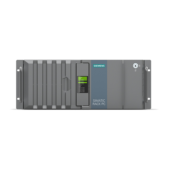
Product description 1.2 Product highlights Product highlights The SIMATIC IPC847E is a powerful industrial PC in 19" rack format design (4 HE). It is perfectly suited for PC applications with high-level industry functionality. Device view Note Depending on the configuration ordered the features and illustrations described in this manual may differ from the features of your device. - Page 14 – All components inside the device can only be accessed when front door is open ● Device monitoring through operating displays on the front for Ethernet; alarms for fan, temperature, watchdog and drives in RAID1 or RAID5 systems SIMATIC IPC847E Operating Instructions, 10/2018, A5E43920357-AA...
-
Page 15: Scope Of Application
The SIMATIC IPC has CE certification for use in the industrial sector as well as in residential and commercial areas and small businesses. In addition to the industrial applications, therefore, it can also be used in building automation or in public facilities. SIMATIC IPC847E Operating Instructions, 10/2018, A5E43920357-AA... -
Page 16: External Design Of The Device
19" mounting bracket ① USB ports ② Reset button ③ On/off button ④ Locking screw of the enclosure cover ⑤ Removable drive bays ⑥ Drive bays See also Interfaces (Page 20) Operator controls (Page 23) SIMATIC IPC847E Operating Instructions, 10/2018, A5E43920357-AA... -
Page 17: Drive Cage Type A
(C) Removable tray (D) Cover Lock of the removable tray Additional information Technical notes and information on the rated conditions are available in the section Drives in drive cage type A / side panel (Page 100). SIMATIC IPC847E Operating Instructions, 10/2018, A5E43920357-AA... -
Page 18: Drive Cage Type B
5.25" drive or components Components Cover or drive cover Cover Additional information Technical notes and information on the rated conditions are available in the section Drives in drive cage type B / side panel (Page 114). SIMATIC IPC847E Operating Instructions, 10/2018, A5E43920357-AA... -
Page 19: Rear Of The Device
Connection for functional ground, see "Connection of equipotential bonding line (Page 50)" ⑥ Interfaces (Page 20) ⑦ Fixing screws for strain relief (here: redundant power supply) ⑧ Slots for expansion cards on the bus board (Page 182) SIMATIC IPC847E Operating Instructions, 10/2018, A5E43920357-AA... -
Page 20: Interfaces And Connections
2 x USB USB 3.1 GEN 2 Type C high current, backwards compatible with X61/X63 USB 3.0/2.0/1.1 ⑧ 2 x 2 USB USB 3.1 GEN 2 Typ A high current, backwards compatible with X60/X62/X64/X65 USB 3.0/2.0/1.1 SIMATIC IPC847E Operating Instructions, 10/2018, A5E43920357-AA... - Page 21 Interfaces at front of device The interfaces at the front of device are located behind the front door. ① 2 × USB 3.1 Gen 1 Connections for USB devices, backward compatible with USB 3.0/2.0/1.1 SIMATIC IPC847E Operating Instructions, 10/2018, A5E43920357-AA...
-
Page 22: Power Supply Connections
Product description 1.4 External design of the device 1.4.5.2 Power supply connections Socket for power plug Sockets for power plugs Single power supply Redundant power supply SIMATIC IPC847E Operating Instructions, 10/2018, A5E43920357-AA... -
Page 23: Operator Controls
The following figures show the location of the on/off switch on the rear of the device for devices with simple or redundant power supply. On/Off switch On/Off switch Single power supply Redundant power supply ① On/Off switch SIMATIC IPC847E Operating Instructions, 10/2018, A5E43920357-AA... - Page 24 The alarm reset button is only available for devices with redundant power supply. Use the alarm reset button to switch off the signal tone of the redundant power supply in the event of an error. ① Alarm reset button SIMATIC IPC847E Operating Instructions, 10/2018, A5E43920357-AA...
-
Page 25: Status Displays
Device temperature is critical • ⑧ Fan status No error Possible causes: Front fan faulty • Fan on drive cage type A faulty • Fan of simple power supply faulty (non- • redundant power supply) SIMATIC IPC847E Operating Instructions, 10/2018, A5E43920357-AA... - Page 26 It may be possible to detect the defective drive with the RAID soft- ware. Information is available at "RAID1 system (Page 65)", "RAID5 system (Page 65)" or "Hot-spare drive in RAID1 or RAID5 systems (Page 66)". SIMATIC IPC847E Operating Instructions, 10/2018, A5E43920357-AA...
-
Page 27: Status Display Of The Ethernet Interface
• Cable disabled • Interface disabled • GREEN Active cable connected • GREEN flashing Data transfer active • LED 2 Data transmission rate 10 Mbps • GREEN 100 Mbps • YELLOW 1000 Mbps • SIMATIC IPC847E Operating Instructions, 10/2018, A5E43920357-AA... -
Page 28: Status Display Of Redundant Power Supply
Power supply not connected • No drive installed • Device is switched on and a drive is in- • stalled ② Activity Status of the Flashes Drive is active • drive Drive is not active • SIMATIC IPC847E Operating Instructions, 10/2018, A5E43920357-AA... -
Page 29: Internal Construction Of The Device
⑥ Motherboard ⑦ Heat sink of the processor ⑧ Rod with card holders for expansion cards ⑨ Bus board with slots for expansion cards ⑩ On the enclosure: Numbering of slots for expansion cards SIMATIC IPC847E Operating Instructions, 10/2018, A5E43920357-AA... -
Page 30: Accessories And Spare Parts
Accessories and spare parts 1.6.1 Hardware accessories Accessories from Siemens are available for your device. These are not included in the scope of delivery. Obtaining accessories from the SIEMENS Industry Mall You can find additional information in the online ordering system Industry Mall (https://mall.industry.siemens.com). - Page 31 Filter pad for fan cover on the device front, A5E37019277 package with 10 filter pads DP to DVI-D Graphics adapter cable, DisplayPort to DVI 6ES7648-3AF00-0XA0 adapter DP to VGA Graphics adapter cable, DisplayPort to VGA 6ES7648-3AG00-0XA0 adapter SIMATIC IPC847E Operating Instructions, 10/2018, A5E43920357-AA...
- Page 32 Mini DisplayPort to DisplayPort, availa- ble as single-pack or 3-pack Component of the optional graphics card SIEMENS spare parts services Information on ordering, the provision and delivery of spare parts can be found under "Industry Online Support: Spare parts services (http://support.automation.siemens.com/WW/view/en/16611927)".
-
Page 33: Software Accessories
Access is possible even if the operating system no longer starts. Further information on the software products and references to the online catalog and ordering system (Industry Mall) can be found on the SIMATIC IPC software (http://www.automation.siemens.com/mcms/pc-based-automation/en/industrial- pc/expansion_components_accessories) homepage. SIMATIC IPC847E Operating Instructions, 10/2018, A5E43920357-AA... - Page 34 Product description 1.6 Accessories and spare parts SIMATIC IPC847E Operating Instructions, 10/2018, A5E43920357-AA...
-
Page 35: Safety Instructions
• For control cabinet mounting: Use a central, easily accessible AC circuit breaker close to the device, if possible. SIMATIC IPC847E Operating Instructions, 10/2018, A5E43920357-AA... - Page 36 Electrostatic sensitive devices (ESD) The device contains electronic components that may be destroyed by electrostatic charges. This can result in malfunctions and damage to the machine or plant. Take corresponding precautionary measures before you open the device. SIMATIC IPC847E Operating Instructions, 10/2018, A5E43920357-AA...
-
Page 37: Note On Transport And Storage
• Bring the device to room temperature before starting it up. • Do not expose the device to direct heat radiation from a heating device. • If condensation develops, wait approximately 12 hours or until the device is completely dry before switching it on. SIMATIC IPC847E Operating Instructions, 10/2018, A5E43920357-AA... -
Page 38: Notes On Mounting
Touching these areas or components can cause death or serious bodily injury. • Always disconnect the cabinet from the mains before opening it. • Ensure that the power to the control cabinet cannot be turned on accidentally. SIMATIC IPC847E Operating Instructions, 10/2018, A5E43920357-AA... -
Page 39: Notes On Ambient And Environmental Conditions
● Always maintain a minimum clearance of 50 mm to the area of the ventilation slots and do not cover the ventilation slots of the enclosure. ● Ensure that there is a distance of at least 50 cm at the back of the device, depending on wiring. SIMATIC IPC847E Operating Instructions, 10/2018, A5E43920357-AA... - Page 40 • Remove radiation sources from the environment of the device. • Switch off radiating devices. • Reduce the radio output of radiating devices. • Read the information on electromagnetic compatibility. • Read the information in the technical specifications. SIMATIC IPC847E Operating Instructions, 10/2018, A5E43920357-AA...
-
Page 41: Information On I/O Devices
• The IPC in question must be turned off and the power supply connector must be plugged • During the measurement, all cables from the plant to the IPC should be connected. • All other components in the plant must be active. SIMATIC IPC847E Operating Instructions, 10/2018, A5E43920357-AA... -
Page 42: Notes On Device And System Extensions
● UL approval of the device only applies when the UL-approved components are used according to their "Conditions of Acceptability". ● We are not liable for functional limitations caused by the use of third-party devices or components. SIMATIC IPC847E Operating Instructions, 10/2018, A5E43920357-AA... -
Page 43: Installing And Connecting The Device
On the supplied data storage medium (read only) you will find: ● Software and tools to recover your ordered Microsoft® Windows® operating system ● Device drivers for installation in operating systems ● SIMATIC IPC847E Quick Install Guide ● SIMATIC IPC847E Operating Instructions ● Product information ●... - Page 44 You will find the latest information on additional software for your device under: Software accessories (Page 33) Printed documents ● SIMATIC IPC847E Quick Install Guide ● Product Information "Important notes on your device" ● SIMATIC IPC/PG Quality Control Report SIMATIC IPC847E...
-
Page 45: Checking The Delivery Package
Fax the enclosed form "SIMATIC IPC/PG Quality Control Report". 5. Please keep the documentation in a safe place. It is required for initial commissioning and is part of the device. 6. Note down the Device identification data (Page 46). SIMATIC IPC847E Operating Instructions, 10/2018, A5E43920357-AA... -
Page 46: Device Identification Data
The COA label is only available for devices delivered with Microsoft® Windows® operating system installed. Example: COA label for the Microsoft® Windows® 10 operating system: See also Important instructions and manuals for operating the device (Page 11) SIMATIC IPC847E Operating Instructions, 10/2018, A5E43920357-AA... -
Page 47: Mounting The Device
For the vertical operation of the device with a tower kit, the device has a cover and feet. The tower kit can be ordered as an option , see "Hardware accessories (Page 30)". Additional information You can also find additional information in the QIG (Quick Installation Guide), which comes with your device. SIMATIC IPC847E Operating Instructions, 10/2018, A5E43920357-AA... -
Page 48: Securing Device
Detailed information on the position of the mounting holes for angle brackets or telescopic rails can be found here: Dimension drawing of the telescope rails (Page 166) and Technical specifications of the telescopic rails (Page 162). SIMATIC IPC847E Operating Instructions, 10/2018, A5E43920357-AA... -
Page 49: Connecting The Device
The power supply cord and the plug connector must bear the prescribed markings. SIMATIC IPC847E Operating Instructions, 10/2018, A5E43920357-AA... -
Page 50: Connection Of Equipotential Bonding Line
● Equipotential bonding conductor with a minimum cross section of 2.5 mm Procedure 1. Make the connection for functional ground via an equipotential bonding line to the equipotential bonding rail or grounding bar of the control cabinet in which the device is installed. SIMATIC IPC847E Operating Instructions, 10/2018, A5E43920357-AA... -
Page 51: Connecting The Power Supply
• For control cabinet mounting: Use a central, easily accessible AC circuit breaker close to the device, if possible. SIMATIC IPC847E Operating Instructions, 10/2018, A5E43920357-AA... - Page 52 Attach latch for power plug To prevent unintentional removal of the power cable, you secure the plug as follows: ① 1. Remove the retaining screw 2. Screw on the latch for the power plug ② SIMATIC IPC847E Operating Instructions, 10/2018, A5E43920357-AA...
-
Page 53: Connecting A Redundant Power Supply (Ac)
• For control cabinet mounting: Use a central, easily accessible AC circuit breaker close to the device, if possible. SIMATIC IPC847E Operating Instructions, 10/2018, A5E43920357-AA... - Page 54 To prevent unintentional removal of the power cable, you secure the plug on the device as follows: ① 1. Remove the two retaining screws ② 2. Screw the power plug latches using the two ① fixing screws SIMATIC IPC847E Operating Instructions, 10/2018, A5E43920357-AA...
-
Page 55: Connecting I/O Devices
● Audio device with line in ● Headphones ● Microphone ● Headset (with headphones and microphone) with the following standards: – OMTP: Standard for audio devices from Nokia, etc. – CTIA: Standard for audio devices from Apple® SIMATIC IPC847E Operating Instructions, 10/2018, A5E43920357-AA... - Page 56 3) - via mDP to DP adapter 4) - via mDP to DVI-D adapter 5) - via mDP to VGA adapter You can find additional information about the optional graphics card under "Technical specifications of graphic (Page 160)". SIMATIC IPC847E Operating Instructions, 10/2018, A5E43920357-AA...
-
Page 57: Connecting The Device To Networks
Control level. Additional information is available under SIMATIC NET (http://w3.siemens.com/mcms/automation/en/industrial- communications/Pages/Default.aspx). The software package and the documentation are not included in the scope of delivery Additional information You can find additional information on the Internet at: Technical support (https://support.industry.siemens.com/cs/ww/en/) SIMATIC IPC847E Operating Instructions, 10/2018, A5E43920357-AA... -
Page 58: Securing The Cables
1. Screw the strain relief onto the de- ② vice with the fastening screw 2. Insert the detachable cable ties in the respective openings of the strain relief and fasten the cables with the cable ties. SIMATIC IPC847E Operating Instructions, 10/2018, A5E43920357-AA... -
Page 59: Commissioning The Device
You can find information on this in the detailed firmware/BIOS description, see "Important instructions and manuals for operating the device (Page 11)". The exact minimum required downtime of the mains voltage is dependent on the device equipment and the application. SIMATIC IPC847E Operating Instructions, 10/2018, A5E43920357-AA... -
Page 60: Switching Off The Device
● Shut down the operating system and unplug the power plug from the rear of the device, see "Power supply connections (Page 22)". The device is switched off and fully disconnected from the mains voltage. No trickle current is flowing. SIMATIC IPC847E Operating Instructions, 10/2018, A5E43920357-AA... - Page 61 – Press the power button again to turn the device back on. Hardware reset with reset button: ● Press the reset button. – The device switches off and on again. Information on the position of the buttons is available under "Operator controls (Page 23)". SIMATIC IPC847E Operating Instructions, 10/2018, A5E43920357-AA...
- Page 62 Commissioning the device 4.3 Switching off the device SIMATIC IPC847E Operating Instructions, 10/2018, A5E43920357-AA...
-
Page 63: Operating The Device
Operating the device Opening the front door Procedure 1. Open the front door with the key. 2. Pull the front door to the side. See also Notes on device and system extensions (Page 42) SIMATIC IPC847E Operating Instructions, 10/2018, A5E43920357-AA... -
Page 64: Multi-Monitoring
2. Configure the function "Multi-monitoring" in the firmware settings of the device. You can find information on this in the detailed firmware/BIOS description, see "Important instructions and manuals for operating the device (Page 11)". SIMATIC IPC847E Operating Instructions, 10/2018, A5E43920357-AA... -
Page 65: Drive Configurations
● Onboard RAID system (Page 68): Intel® Rapid Storage Technology ● Hardware RAID system (Page 73): maxView Storage Manager See also Drive cage type A (Page 17) Installing drives inside on the side wall of the device (Page 124) SIMATIC IPC847E Operating Instructions, 10/2018, A5E43920357-AA... -
Page 66: Hot-Spare Drive In Raid1 Or Raid5 Systems
You have the option of backing up your data to this drive. You can find information on how to boot the device from the second drive in the detailed firmware/BIOS description, see "Important instructions and manuals for operating the device (Page 11)". SIMATIC IPC847E Operating Instructions, 10/2018, A5E43920357-AA... -
Page 67: Operating Raid Systems
Storage Manager" (Page 80)". 5.4.2 RAID1 system: Installation options for drives The two hard disks required for a RAID1 system may be installed in SIMATIC IPC847E at the following locations: ● For onboard RAID system: – Drive cage type A, see "Drives in drive cage type A / side panel (Page 100)"... -
Page 68: Operating Onboard Raid System
6. In the next window, enter a name for the RAID system. 7. Select "RAID Level" and select "RAID1" or "RAID5" in the following selection window, depending on which RAID system you want to set up. A list of available drives is displayed. SIMATIC IPC847E Operating Instructions, 10/2018, A5E43920357-AA... - Page 69 If the warning message "Exit Discarding Changes" is displayed when exiting the firmware/BIOS menu with the <Esc> key, confirm this message with "Yes". The settings made are still saved and you can exit the firmware/BIOS menu. SIMATIC IPC847E Operating Instructions, 10/2018, A5E43920357-AA...
-
Page 70: Monitoring The Onboard Raid System With "Intel® Rapid Storage Technology
– a defective drive – a/the functioning drives Example display status of a RAID1 system: Creating a report on the onboard RAID system 1. Select the "Help" tab. 2. Select "System Report" > "Save". SIMATIC IPC847E Operating Instructions, 10/2018, A5E43920357-AA... -
Page 71: Integrating A New Drive Into The Onboard Raid System
You can configure the manual integration of the drive or check the settings yourself. 1. Select "Start" > "Intel" > "Intel Rapid Storage Technology". 2. Select the "Preferences" menu. 3. Go to the "Automatic Rebuild" area and deactivate the "Auto-rebuild on hot plug" option. SIMATIC IPC847E Operating Instructions, 10/2018, A5E43920357-AA... -
Page 72: Integrating A Hot-Spare Drive Into The Onboard Raid System
The new drive is found and displayed. 3. Select the new drive under "Storage system view" and select "Mark as Spare" under "Manage disk". 4. Confirm the warning message in the "Mark as Spare" window with "Yes". SIMATIC IPC847E Operating Instructions, 10/2018, A5E43920357-AA... -
Page 73: Operating The Hardware Raid System
The "Hardware RAID" function described below is only available as of a later stage of delivery. Contact your local SIEMENS representative. When ordering a device with hardware RAID system, all required software is already installed on your device when it is delivered. -
Page 74: Installing The Hardware Raid Adapter Card
RAID adapter card. Requirement ● 4 GB main memory ● T10 screwdriver ● Components for installing the hardware RAID adapter card. Information on these components can be obtained from your local SIEMENS representative. ① Capacitor block cable with plug ② Capacitor block ③... - Page 75 5.4 Operating RAID systems NOTICE Capacitor block must be discharged The original Siemens spare part is supplied with discharged capacitor block. When you remove or install a charged capacitor block, the Hardware RAID adapter card may be damaged. Data loss may result.
- Page 76 6. Insert the connector of the capacitor block cable at the marked position ② 7. Insert the adapter cable at the marked position Make sure that the connector latch audibly engages. 8. Close the device. 9. Configure the installed hardware RAID adapter card. SIMATIC IPC847E Operating Instructions, 10/2018, A5E43920357-AA...
-
Page 77: Configuring The Hardware Raid System
Select entry Arrow keys on the keyboard • • Confirm selection <Return> key • • Exception: Exception: – Confirm selection when integrating drives: – <Space> keyboard Back to previous window <Esc> key • • SIMATIC IPC847E Operating Instructions, 10/2018, A5E43920357-AA... - Page 78 11. Under "Logical Drive Label", enter a name for your RAID system. 12. Select [Submit Changes] to save your settings. The message "Logical Drive Creation Successful" is displayed in the next window. 13. Select [Back to Main Menu]. SIMATIC IPC847E Operating Instructions, 10/2018, A5E43920357-AA...
- Page 79 <Disabled> Controller Cache <Enabled> 3. Select [Submit Changes] to save your settings. 4. Select [Back to Main Menu]. 5. Finish the process by pressing the <ESC> key repeatedly. 6. Select [Exit Descarding Changes]: Yes SIMATIC IPC847E Operating Instructions, 10/2018, A5E43920357-AA...
-
Page 80: Monitoring The Hardware Raid System With "Maxview Storage Manager
Warning message the first time "maxView Storage Manager" is called 1. Open the Internet Explorer. 2. Open "maxView Storage Manager" with the link on your desktop. A warning message appears about the security certificate of the website. Install the security certificate. SIMATIC IPC847E Operating Instructions, 10/2018, A5E43920357-AA... - Page 81 Monitoring the hardware RAID system with "maxView Storage Manager" You can find detailed information on using "maxView Storage Manager" in the user guide for the software, see "Software and documentation for the hardware RAID system (Page 73)". SIMATIC IPC847E Operating Instructions, 10/2018, A5E43920357-AA...
-
Page 82: Data Synchronization In The Raid System
● < 3 h with 90% HDD system load and RAID5 with HDD 1 TB. In addition, system performance may be limited in the case of a manually started maintenance operation until completion of the maintenance phase. SIMATIC IPC847E Operating Instructions, 10/2018, A5E43920357-AA... -
Page 83: Monitoring Of The Device
Reset on: A hardware reset is car- • A change to the monitoring time is effective immedi- • ried out ately. Reset off: No action is carried out • The device is restarted. • The device is shut down. • SIMATIC IPC847E Operating Instructions, 10/2018, A5E43920357-AA... - Page 84 ● SIMATIC IPC DiagBase (Page 85) for monitoring and alarm output locally on the device ● SIMATIC IPC DiagMonitor (Page 85) for monitoring and alarm output via the network SIMATIC DiagBase or SIMATIC DiagMonitor also controls the status displays of the IPC, see: System status displays (Page 25). SIMATIC IPC847E Operating Instructions, 10/2018, A5E43920357-AA...
-
Page 85: Simatic Ipc Diagbase
● Important instructions and manuals for operating the device (Page 11) Note SIMATIC IPC DiagMonitor only supports the device hardware as of version 5.1.0. Older versions do not support the device hardware. See also Software accessories (Page 33) SIMATIC IPC847E Operating Instructions, 10/2018, A5E43920357-AA... -
Page 86: Remote Maintenance Of The Device
(Page 11). Software for remote maintenance of the device You can find information about the software for remote maintenance of the device and its documentation under: ● SIMATIC IPC Remote Manager (Page 87) SIMATIC IPC847E Operating Instructions, 10/2018, A5E43920357-AA... -
Page 87: Simatic Ipc Remote Manager
You can find information on the software and documentation of SIMATIC IPC Remote Manager under: ● SIMATIC IPC Remote Manager (http://support.automation.siemens.com/WW/view/en/48707158) ● Important instructions and manuals for operating the device (Page 11) SIMATIC IPC847E Operating Instructions, 10/2018, A5E43920357-AA... -
Page 88: Trusted Platform Module (Tpm)
Activate Trusted Platform Modules You can find information on activating the Trusted Platform Module in the detailed firmware/BIOS description, see "Important instructions and manuals for operating the device (Page 11)". See also Support for TPM 2.0 (https://support.microsoft.com/en-us/) SIMATIC IPC847E Operating Instructions, 10/2018, A5E43920357-AA... -
Page 89: Expanding And Assigning Parameters To The Device
● The front door is open; see "Opening the front door (Page 63)". ● The device is fully disconnected from the line voltage, see "Switching off the device (Page 60)". ● All connection cables are unplugged. ● T10 screwdriver SIMATIC IPC847E Operating Instructions, 10/2018, A5E43920357-AA... - Page 90 Expanding and assigning parameters to the device 6.1 Open the device Procedure 1. Remove the captive ① screw 2. Push the enclosure cover back. 3. Lift up and remove the enclosure cover. SIMATIC IPC847E Operating Instructions, 10/2018, A5E43920357-AA...
-
Page 91: Expansion Cards
● You are familiar with the information on expansion cards and the conditions of use of expansion cards, see "Useable expansion cards (Page 91)". ● The device is open, see important information in "Open the device (Page 89)". SIMATIC IPC847E Operating Instructions, 10/2018, A5E43920357-AA... - Page 92 If you are installing a low-profile expansion card, use the longer card holder for mounting (included in product package). 9. Secure the cables with the cable ③ holder 10. Close the device. SIMATIC IPC847E Operating Instructions, 10/2018, A5E43920357-AA...
-
Page 93: Removing Expansion Cards
4. Remove the expansion card from the ③ slot 5. If you do not wish to install a new expansion card, install the corresponding slot bracket with the ② screw SIMATIC IPC847E Operating Instructions, 10/2018, A5E43920357-AA... -
Page 94: Memory Modules
See also Open the device (Page 89) SIMATIC IPC847E Operating Instructions, 10/2018, A5E43920357-AA... -
Page 95: Removing Memory Modules
3. Close the device. Display of a changed memory configuration A new memory configuration is detected automatically. The allocation of the "base memory and extended memory" is automatically displayed when you switch on the device. SIMATIC IPC847E Operating Instructions, 10/2018, A5E43920357-AA... -
Page 96: Installing Memory Modules
When inserting the base, note the marked cutout must match up with the coding of the base. 3. Open the two locks on the left and right of the slot. 4. Insert the memory module in the slot perpendicular to the motherboard. SIMATIC IPC847E Operating Instructions, 10/2018, A5E43920357-AA... - Page 97 6. Close the device. Display of a changed memory configuration A new memory configuration is detected automatically. The allocation of the "base memory and extended memory" is automatically displayed when you switch on the device. SIMATIC IPC847E Operating Instructions, 10/2018, A5E43920357-AA...
-
Page 98: Internal Usb Interface
1. Screw the guide rail of the retainer into place in the enclosure as shown in the figure. 2. Connect the USB stick. 3. Slide the retainer in the direction of the USB stick. 4. Secure the retainer by turning the screw on the guide rail. SIMATIC IPC847E Operating Instructions, 10/2018, A5E43920357-AA... -
Page 99: Graphics Card
You can find information on removing the graphics card under "Removing expansion cards (Page 93)". Installing the graphics card You can find information on installing the graphics card under "Installing expansion cards (Page 91)". SIMATIC IPC847E Operating Instructions, 10/2018, A5E43920357-AA... -
Page 100: Drives
④ Drive type "SATA, SATA En- terprise and SAS Enterprise" is possible ⑤ Additional drive mount- ed on the right side panel on the drive bay plate. ⑥ Drive type "SATA, SATA-Enterprise" is possible SIMATIC IPC847E Operating Instructions, 10/2018, A5E43920357-AA... - Page 101 SATA (2.5" and 3.5" size) SATA Enterprise (2.5" and 3.5" size) SAS Enterprise (3.5" size) * 0 °C minimum permissible temperature for SATA hard disk drive 5°C minimum permissible temperature for SATA Enterprise hard disk drives SIMATIC IPC847E Operating Instructions, 10/2018, A5E43920357-AA...
-
Page 102: Permissible Expansion For Temperature Range 0 To 50 °C
The maximum permitted power loss of the expansion cards is 80 W. Ambient temperature 0 - 50 °C Drive configuration Mode Non-RAID system RAID1 system RAID5 system RAID1 system with hot spare drive RAID5 system with hot spare drive SIMATIC IPC847E Operating Instructions, 10/2018, A5E43920357-AA... - Page 103 (in the removable tray or internally on the side panel of the device) Ambient temperature 0 - 50 °C Drive type Front Side panel SATA (2.5" and 3.5" size) SATA Enterprise (2.5" and 3.5" size) SAS Enterprise (3.5" size) SIMATIC IPC847E Operating Instructions, 10/2018, A5E43920357-AA...
-
Page 104: Change 2.5" And 3.5" Drive In Removable Tray
● If there is no RAID system: The device is fully disconnected from the line voltage, see "Switching off the device (Page 60)". ● The device you wish to replace is inactive. ● When replacing an HD: T10 screwdriver ● When replacing an SSD: T8 screwdriver SIMATIC IPC847E Operating Instructions, 10/2018, A5E43920357-AA... - Page 105 9. Fold the tray bracket out of the removable tray as far as it will go and slide the removable tray fully into the drive cage. Ensure that the removable tray fits tightly in the drive cage. SIMATIC IPC847E Operating Instructions, 10/2018, A5E43920357-AA...
- Page 106 Expanding and assigning parameters to the device 6.6 Drives 10. Close the tray bracket. 11. Lock the removable tray with the key. Note The removable tray must always be locked to ensure reliable operation of the devices with removable trays. SIMATIC IPC847E Operating Instructions, 10/2018, A5E43920357-AA...
-
Page 107: Installing A 5.25" Adapter Module For Removable Trays
1. Unlock the drive mounting bar together with the blanking plate by pressing laterally ① against the surfaces and push the drive mounting bar forward from the device in the direction of the arrow. 2. Remove the blanking plate. SIMATIC IPC847E Operating Instructions, 10/2018, A5E43920357-AA... - Page 108 3. Push the 5.25" adapter for the removable racks from the front into the drive cage. 4. Attach the data cables to the desired connectors on the motherboard or the hardware RAID controller and to the adapter module. 5. Connect the power supply. 6. Close the device. SIMATIC IPC847E Operating Instructions, 10/2018, A5E43920357-AA...
-
Page 109: Installing A Backplane For Removable Tray
● The device is open, see important information in "Open the device (Page 89)". Procedure ① ② 1. Press the locks of the cover together inside the device and keep them pressed. 2. Push the locks to the front in the direction of the arrow. SIMATIC IPC847E Operating Instructions, 10/2018, A5E43920357-AA... - Page 110 5. Remove all existing removable trays until the drive cage is freely accessible. ④ 6. Insert the backplane into the drive bay from the front and snap it into place at the back. SIMATIC IPC847E Operating Instructions, 10/2018, A5E43920357-AA...
- Page 111 9. At the backplane, connect the data cables with the corresponding interfaces on the motherboard or the hardware RAID controller. 10. Connect the power supply. 11. Close the device. SIMATIC IPC847E Operating Instructions, 10/2018, A5E43920357-AA...
-
Page 112: Changing A Backplane For Removable Tray
1. Note the assignment of all data cables to the motherboard and disconnect all data cables ① 2. Unlock the backplane by pressing firmly in the direction of the arrow on the latching lugs ② ③ and press the ejector SIMATIC IPC847E Operating Instructions, 10/2018, A5E43920357-AA... - Page 113 Expanding and assigning parameters to the device 6.6 Drives ④ 3. Remove the unlatched backplane board by turning it upwards from the brackets and removing it from the drive cage. See also Installing a backplane for removable tray (Page 109) SIMATIC IPC847E Operating Instructions, 10/2018, A5E43920357-AA...
-
Page 114: Drives In Drive Cage Type B / Side Panel
If drives are installed in one of the mounting locations, these may be exposed to the following vibration stresses during operation: ● 10 ... 58 Hz: 0.075 mm ● 58 ... 500 Hz: 5 m/s SIMATIC IPC847E Operating Instructions, 10/2018, A5E43920357-AA... - Page 115 0 * - 40 °C Drive type Front Side panel SATA SATA Enterprise * 0 °C minimum permissible temperature for SATA hard disk drive 5°C minimum permissible temperature for SATA Enterprise hard disk drives SIMATIC IPC847E Operating Instructions, 10/2018, A5E43920357-AA...
-
Page 116: Permissible Expansion For Temperature Range 0 To 50 °C
If drives are installed in one of the mounting locations, these may be exposed to the following vibration stresses during operation: ● 10 ... 58 Hz: 0.075 mm ● 58 ... 500 Hz: 5 m/s SIMATIC IPC847E Operating Instructions, 10/2018, A5E43920357-AA... - Page 117 Maximum number of drives per drive type (in drive cage type B or internally on the side panel of the device) Ambient temperature 0 - 50 °C Drive type Front Side panel SATA SATA Enterprise SIMATIC IPC847E Operating Instructions, 10/2018, A5E43920357-AA...
-
Page 118: Change 2.5" And 3.5" Drive In Assembly Kit For 5.25" Tray
"Switching off the device (Page 60)". ● The device is open, see important information in "Open the device (Page 89)". ● When replacing an HD: T10 screwdriver ● When replacing an SSD: T8 screwdriver SIMATIC IPC847E Operating Instructions, 10/2018, A5E43920357-AA... - Page 119 Note: The drive mounting bars are labeled with "L" and "R" and must be remounted in the same ③ way on the "left" and "right", see corresponding marking on drive bay cover SIMATIC IPC847E Operating Instructions, 10/2018, A5E43920357-AA...
- Page 120 5. Install the new drive in the drive bay . Ensure that the new drive faces upwards. ④ 6. Fasten the new drive with four screws . Start at the hole marked with "1" on the drive bay. SIMATIC IPC847E Operating Instructions, 10/2018, A5E43920357-AA...
- Page 121 10. Push the drive bay in fully and evenly on the left and the right until you hear it click into the drive cage. 11. Connect the power and data cables to the drive. SIMATIC IPC847E Operating Instructions, 10/2018, A5E43920357-AA...
-
Page 122: Installing A 5.25" Drive
1. Unlock the drive mounting bar together with the blanking plate by pressing laterally ① against the surfaces and push the drive mounting bar forward from the device in the direction of the arrow. SIMATIC IPC847E Operating Instructions, 10/2018, A5E43920357-AA... - Page 123 5. Push the new drive with the drive mounting bars in the guide rail on the left and right into the drive cage evenly at the back without tilting until it snaps into place. SIMATIC IPC847E Operating Instructions, 10/2018, A5E43920357-AA...
-
Page 124: Installing Drives Inside On The Side Wall Of The Device
● The device is fully disconnected from the line voltage, see "Switching off the device (Page 60)". ● The device is open, see important information in "Open the device (Page 89)". Procedure 1. Screw the drive to the drive bay plate at the highlighted holes. SIMATIC IPC847E Operating Instructions, 10/2018, A5E43920357-AA... - Page 125 The SATA connectors are always located at the top 3. Connect the data cables to the desired connectors on the motherboard and on the drive ③ (position 4. Connect the power supply. 5. Close the device. SIMATIC IPC847E Operating Instructions, 10/2018, A5E43920357-AA...
-
Page 126: Install M.2 Nvme Ssd
The M.2 NVMe SSD is plugged onto a PCIe adapter card and then onto the bus board using this adapter card. Requirement ● M.2 NVMe SSDs key M with a max. length of 110 mm ● PCIe adapter card ● Cross-tip screwdriver P1 SIMATIC IPC847E Operating Instructions, 10/2018, A5E43920357-AA... - Page 127 3. Install the PCIe adapter card in the corresponding slot on the bus board. – Read the information under "Slots for expansion cards on the bus board (Page 182)" and "Installing expansion cards (Page 91)". SIMATIC IPC847E Operating Instructions, 10/2018, A5E43920357-AA...
- Page 128 Expanding and assigning parameters to the device 6.6 Drives SIMATIC IPC847E Operating Instructions, 10/2018, A5E43920357-AA...
-
Page 129: Device Maintenance And Repair
As soon as the Smart status of the SSD goes to "Not OK", a message is generated in SIMATIC DiagBase or SIMATIC DiagMonitor or during a system start of the device. You should then back up your data and replace the drive. SIMATIC IPC847E Operating Instructions, 10/2018, A5E43920357-AA... -
Page 130: Removing And Installing Hardware
2. Insert the new filter pad into the fan cover. It is inserted loosely in the fan cover. When you insert the filter pad, make sure it lies evenly in the fan cover. 3. Replace the fan cover. See also Maintenance intervals (Page 129) SIMATIC IPC847E Operating Instructions, 10/2018, A5E43920357-AA... -
Page 131: Replacing Device Fans
1. Open the front door at least at an angle of approx. 45°. 2. Take hold of the recessed grip of ① the fan cover 3. Open the fan cover in the direction of the arrow and remove SIMATIC IPC847E Operating Instructions, 10/2018, A5E43920357-AA... -
Page 132: Changing The Front Fan
3. Put down the fan support with the openings facing down (fan is above). ② 4. Press on the clip on the small fan cable plug connector and remove the connector from the larger adapter plug, SIMATIC IPC847E Operating Instructions, 10/2018, A5E43920357-AA... - Page 133 9. Then place the new fan on the fan support. ⑦ Use the highlighted positions as a guide. Notch in fan support and holder for adapter ⑥ plug ④ 10. Snap the fan into place at the locking latches of the fan support SIMATIC IPC847E Operating Instructions, 10/2018, A5E43920357-AA...
- Page 134 12. Insert the small fan cable connector in the larger adapter connector again. 13. Place the fan support with the new fan on the front of the device. See also Maintenance intervals (Page 129) SIMATIC IPC847E Operating Instructions, 10/2018, A5E43920357-AA...
-
Page 135: Change The Fan On Drive Cage Type A
The fan holder is labeled as follows: – At the top with "Top" – At the bottom with arrows which indicate the direction of rotation and air flow of the fan. SIMATIC IPC847E Operating Instructions, 10/2018, A5E43920357-AA... - Page 136 7. Finally, snap the new fan completely into place in the locking latches 8. Mount the fan support on the drive cage (see above). 9. Connect the fan cable to the motherboard. See also Maintenance intervals (Page 129) SIMATIC IPC847E Operating Instructions, 10/2018, A5E43920357-AA...
-
Page 137: Changing The Backup Battery
(Page 11)". ● The device is open, see important information in "Open the device (Page 89)". ● You have observed the local regulations relating to the disposal of used batteries. SIMATIC IPC847E Operating Instructions, 10/2018, A5E43920357-AA... - Page 138 "Removing expansion cards (Page 93)". 2. Remove the battery from socket. 3. Press the new battery into the socket applying slight pressure. 4. Close the device. 5. Check the firmware settings. See also Hardware accessories (Page 30) SIMATIC IPC847E Operating Instructions, 10/2018, A5E43920357-AA...
-
Page 139: Changing A Single Power Supply (Ac)
7. Connect the cables to the drives and the motherboard. 8. Use cable ties to reattach the power supply cables to the enclosure. 9. Close the device. 10. Check the safe state of the device. 11. Switch on the power supply. SIMATIC IPC847E Operating Instructions, 10/2018, A5E43920357-AA... -
Page 140: Replacing Redundant Power Supply (Ac) Module
7. Plug the power cord into the socket of the newly inserted module 8. Check the safe state of the device. ② 9. Switch on the module again with the on/off switch (status display on top of module is lit green). SIMATIC IPC847E Operating Instructions, 10/2018, A5E43920357-AA... -
Page 141: Changing The Enclosure Of The Redundant Power Supply (Ac)
● Short Phillips screwdriver P1 Procedure 1. Remove the cable ties securing the power cables in the enclosure. 2. Disconnect the cables from the drives and the motherboard. ① 3. Unscrew the marked screw inside the device enclosure. SIMATIC IPC847E Operating Instructions, 10/2018, A5E43920357-AA... - Page 142 5. Remove the housing of the redundant power supply from the back of the device. 6. Install the new enclosure and secure it at the appropriate places. 7. Re-insert the two modules of the redundant power supply and close the device. SIMATIC IPC847E Operating Instructions, 10/2018, A5E43920357-AA...
-
Page 143: Replacing The Bus Board
3. Remove the screws marked in the figure. 4. Pull the bus board from the mother- board. Procedure - Installation Proceed in the reverse order for the installation. See also Bus board (Page 182) SIMATIC IPC847E Operating Instructions, 10/2018, A5E43920357-AA... -
Page 144: Replacing The Processor
During positioning, make sure to take the highlighted arrow on the processor into consideration. 6. Lock the processor in place. 7. Install the heat sink of the processor again. 8. Install the bus board again. SIMATIC IPC847E Operating Instructions, 10/2018, A5E43920357-AA... -
Page 145: Replacing The Motherboard
6. Fasten the COM1 interface and the DVI-D interface with the previously released hexagon bolts. 7. Fasten the new motherboard with the previously loosened hexagon bolts and fixing screws. 8. Reconnect the cables at the correct positions on the motherboard. SIMATIC IPC847E Operating Instructions, 10/2018, A5E43920357-AA... - Page 146 – Expansion cards, see "Installing expansion cards (Page 91)". 10. Update the firmware settings to match the version of the motherboard. Please note during the update whether you are operating a device with or without a RAID system. SIMATIC IPC847E Operating Instructions, 10/2018, A5E43920357-AA...
-
Page 147: Installing Operating System, Software And Drivers
Contact a certified disposal service company for electronic scrap for environmentally sound recycling and disposal of your old device, and dispose of it according to the relevant regulations in your country. SIMATIC IPC847E Operating Instructions, 10/2018, A5E43920357-AA... - Page 148 Device maintenance and repair 7.7 Recycling and disposal SIMATIC IPC847E Operating Instructions, 10/2018, A5E43920357-AA...
-
Page 149: Technical Specifications
• The device is closed. • The connected I/O devices meet the requirements for the respective area of application (interference emission according to EN 61000-6-3 / IEC 61000-6-3, immunity to interference according to EN 61000-6-2 / IEC 61000-6-2). SIMATIC IPC847E Operating Instructions, 10/2018, A5E43920357-AA... -
Page 150: General Technical Specifications
+5 V/20 A, +3.3 V/20 A • 100 W permitted in total +12 V1/16 A, +12 V2/16 A • -12 V/0.5 A, +5 V /3 A • The total power of all voltages may not exceed 255 W. SIMATIC IPC847E Operating Instructions, 10/2018, A5E43920357-AA... - Page 151 2500 V) Safety regulations IEC 61010-2-201 • EN 61010-2-201 • UL 61010-2-201 • CSA C22.2 No 61010-2-201 • Only with protected installation, see "Notes on ambient and environmental conditions (Page 39)" SIMATIC IPC847E Operating Instructions, 10/2018, A5E43920357-AA...
-
Page 152: Current/Power Requirements And Power Supply
Depends on the selected device configuration The accumulated power of the +5 V and + 3.3 V voltage may not exceed 190 W with ATX power supply and 100 W with ATX redundant. 2.5 A for 10 seconds SIMATIC IPC847E Operating Instructions, 10/2018, A5E43920357-AA... - Page 153 1 × SSD 2.5" drive SATA 0.02 A 3.6 W 1 x M.2 NVMe SSD 0.03 A 5.9 W Triple Head graphics card 0.14 A 32.8 W Hardware RAID controller 0.07 A 15 W SIMATIC IPC847E Operating Instructions, 10/2018, A5E43920357-AA...
-
Page 154: Technical Specifications Of Single Power Supply (Ac)
The total output of the +5 V and +3.3 V voltage must be ≤ 100 W. The total current of the +12 V voltage must be ≤ 25 A. The total power of all voltages is max. 350 W. SIMATIC IPC847E Operating Instructions, 10/2018, A5E43920357-AA... -
Page 155: Electromagnetic Compatibility
3 V/m; 2.7 to 6 GHz • 80% AM to IEC 61000-4-3 10 V; 10 kHz up to 80 MHz • 80% AM to IEC 61000-4-6 Magnetic field 100 A/m; 50 Hz; 60 Hz (according to IEC 61000-4-8) SIMATIC IPC847E Operating Instructions, 10/2018, A5E43920357-AA... -
Page 156: Ambient Conditions
B drive cages see "Permissible expansion for temperature range 0 to 40 °C (Page 114)" and "Permissible expansion for temperature range 0 to 50 °C (Page 116)". The device must be free of any mechanical faults when disk drives are installed in the removable tray. SIMATIC IPC847E Operating Instructions, 10/2018, A5E43920357-AA... -
Page 157: Technical Specifications Of The Drives
M.2 NVMe SSD M.2-2280 key M, PCIe Gen3 x4 *; 512 GB and 1024 GB You can find the maximum theoretical data rate of a PCIe lane in the technical specifications of the device SIMATIC IPC847E Operating Instructions, 10/2018, A5E43920357-AA... -
Page 158: Technical Specifications Of The Motherboard
Power loss of all slots with max. ≤ 80 W ambient air temperature 50 °C, In sum, the current for 3.3 V may not exceed 1.2 A. permissible Main memory interface 2400 MT/s SIMATIC IPC847E Operating Instructions, 10/2018, A5E43920357-AA... - Page 159 2 x PCIe x4 (4 lanes, via PCIe switch); Gen 3.0** • * PCIe bus of the CPU ** PCIe bus of the PCH For information on this, see "Slots for expansion cards on the bus board (Page 182)". SIMATIC IPC847E Operating Instructions, 10/2018, A5E43920357-AA...
-
Page 160: Technical Specification Of The Hardware Raid Adapter Card
– 1x DisplayPort 5120 × 2880 at 60 Hz; 32-bit color depth – DVI 1920 × 1200 at 60 Hz; 32-bit color depth – VGA 2048 × 1536 at 60 Hz; 32-bit color depth SIMATIC IPC847E Operating Instructions, 10/2018, A5E43920357-AA... -
Page 161: Technical Specifications Of The Interfaces
Use the original connections of the I/O to be connected without adapters or extensions. AMT and teaming cannot be used simultaneously on the Ethernet interface. See also Dimension drawing of the device (Page 163) SIMATIC IPC847E Operating Instructions, 10/2018, A5E43920357-AA... -
Page 162: Technical Specifications Of The Telescopic Rails
Partition Name Size File system First Boot 260 MB FAT32 Second 128 MB None Third System 160 GB NTFS, not compressed Fourth WinRE 500 MB NTFS, not compressed Fifth Data Remainder NTFS, not compressed SIMATIC IPC847E Operating Instructions, 10/2018, A5E43920357-AA... -
Page 163: Dimension Drawings
Dimension drawing of the device Note IEC 60297-3-100 The systems meets the requirements for 4 HE according to IEC 60297-3-100. Front view and top view 1) At top when installed vertically. All dimensions in mm. SIMATIC IPC847E Operating Instructions, 10/2018, A5E43920357-AA... -
Page 164: Dimension Drawing Of The Tower Kit
Dimension drawings 9.2 Dimension drawing of the Tower Kit Dimension drawing of the Tower Kit Front view and top view SIMATIC IPC847E Operating Instructions, 10/2018, A5E43920357-AA... -
Page 165: Dimension Drawing Of The Expansion Cards
Lower edge of expansion card to lower edge of retainer DIM C 113.44 mm 117.9 mm Lower edge of expansion card to retainer DIM D 123.54 mm 128.0 mm Lower edge of expansion card to bottom of device cover SIMATIC IPC847E Operating Instructions, 10/2018, A5E43920357-AA... -
Page 166: Dimension Drawing Of The Telescope Rails
Dimension drawings 9.4 Dimension drawing of the telescope rails Dimension drawing of the telescope rails Dimensions for bore holes for telescopic rails SIMATIC IPC847E Operating Instructions, 10/2018, A5E43920357-AA... -
Page 167: Standards And Approvals
● 2011/65/EU "Restriction of the use of certain hazardous substances in electrical and electronic equipment" (RoHS Directive) EC Declaration of Conformity The associated declaration of conformity is available on the Internet at the following address: Rack PC certificates (http://support.automation.siemens.com/WW/view/en/10805674/134200). SIMATIC IPC847E Operating Instructions, 10/2018, A5E43920357-AA... -
Page 168: Din Iso 9001 Certificate And Software License Agreements
DIN ISO 9001 certificate and software license agreements ISO 9001 certificate The Siemens quality management system for our entire product creation process (development, production and sales) meets the requirements of ISO 9001. This has been certified by DQS (the German society for the certification of quality management systems). -
Page 169: Fcc (Usa)
(1) this device may not cause harmful interference, and (2) this device must accept any interference received, including interference that may cause undesired operation. Responsible party for Supplier's Declaration of Conformity Siemens Industry, Inc. Digital Factory - Factory Automation 5300 Triangle Parkway, Suite 100 Norcross, GA 30092 mail to: amps.automation@siemens.com... -
Page 170: Australia / New Zealand
This product meets the requirements of Korean certification. This product satisfies the requirement of the Korean Certification (KC Mark). 이 기기는 업무용(A급) 전자파 적합기기로서 판매자 또는 사용자는 이 점을 주의하시기 바라며 가정 외의 지역에서 사용하는 것을 목적으로 합니다. SIMATIC IPC847E Operating Instructions, 10/2018, A5E43920357-AA... -
Page 171: Hardware Description
Slots for memory modules ② Processor ③ Slot for the bus board ④ Backup battery Technical features of the motherboard Technical features of the motherboard can be found under "Technical specifications of the motherboard (Page 158)". SIMATIC IPC847E Operating Instructions, 10/2018, A5E43920357-AA... -
Page 172: Position Of The Interfaces On The Motherboard
LAN 2 (X2 P1) SATA 0 (Port 0) LAN 3 (X3 P1) Status indicator on front On-off button Reset button USB 3.1 USB 3.0 behind front door (X60-X65) 2x type A 4x type A 2x type C SIMATIC IPC847E Operating Instructions, 10/2018, A5E43920357-AA... -
Page 173: Internal Interfaces
PEG interface (PCIe x16 sock- Transfer interface between motherboard and bus board PCIe+special signal interface (PCIe x16 socket) A special USB stick is required (not included in scope of delivery; contact your local SIEMENS representative). SIMATIC IPC847E Operating Instructions, 10/2018, A5E43920357-AA... -
Page 174: Scsi Activity Connector
NOTICE Observe safety information Only use this interface for maintenance purposes. You should observe the warnings in "Open the device (Page 89)". Name Meaning EXT_PWRBTN Input, 0 V level means Power button pressed Ground SIMATIC IPC847E Operating Instructions, 10/2018, A5E43920357-AA... -
Page 175: Internal Interface Connector (Usb 2.0)
Data channel USB2, bidirectional Reserved + 5 V (fused) or ground USB2 (USB 2.0 contacts) -Data Data channel USB2 +Data Data channel USB2 Ground B4, 5 Open Ground B7, 8 Open + 5 V (fused) Open SIMATIC IPC847E Operating Instructions, 10/2018, A5E43920357-AA... -
Page 176: Power Supply Fan Monitoring
Tacho signal Input monitoring signal Output speed setting A.2.9 Supply for the serial ATA drives Name Meaning +12 V Output power supply Ground Ground +5 V Output power supply +3.3 V Output power supply SIMATIC IPC847E Operating Instructions, 10/2018, A5E43920357-AA... -
Page 177: Peg Interface (Pcie X16 Socket)
PCIE_RESET_L n.c. PCIE0_ECLK PCIEX16_TX_P(15) PCIE0_ECLK_N PCIEX16_TX_N(15) PCIEX16_RX_P(15) SDVO_CTRLCLK PCIEX16_RX_N(15) PCIEX16_TX_P(14) n.c. PCIEX16_TX_N(14) PCIEX16_RX_P(14) PCIEX16_RX_N(14) PCIEX16_TX_P(13) PCIEX16_TX_N(13) PCIEX16_RX_P(13) PCIEX16_RX_N(13) PCIEX16_TX_P(12) PCIEX16_TX_N(12) PCIEX16_RX_P(12) n.c. PCIEX16_RX_N(12) SDVO_CTRLDATA n.c. PCIEX16_TX_P(11) n.c. PCIEX16_TX_N(11) PCIEX16_RX_P(11) PCIEX16_RX_N(11) PCIEX16_TX_P(10) PCIEX16_TX_N(10) PCIEX16_RX_P(10) PCIEX16_RX_N(10) SIMATIC IPC847E Operating Instructions, 10/2018, A5E43920357-AA... - Page 178 PCIEX16_TX_N(7) PCIEX16_RX_P(7) PCIEX16_RX_N(7) PCIEX16_TX_P(6) PCIEX16_TX_N(6) PCIEX16_RX_P(6) PCIEX16_RX_N(6) PCIEX16_TX_P(5) PCIEX16_TX_N(5) PCIEX16_RX_P(5) PCIEX16_RX_N(5) PCIEX16_TX_P(4) PCIEX16_TX_N(4) PCIEX16_RX_P(4) PCIEX16_RX_N(4) PCIEX16_TX_P(3) PCIEX16_TX_N(3) PCIEX16_RX_P(3) PCIEX16_RX_N(3) PCIEX16_TX_P(2) PCIEX16_TX_N(2) PCIEX16_RX_P(2) PCIEX16_RX_N(2) PCIEX16_TX_P(1) PCIEX16_TX_N(1) PCIEX16_RX_P(1) PCIEX16_RX_N(1) PCIEX16_TX_P(0) PCIEX16_TX_N(0) PCIEX16_RX_P(0) n.c. PCIEX16_RX_N(0) n.c. SIMATIC IPC847E Operating Instructions, 10/2018, A5E43920357-AA...
-
Page 179: Pcie + Special Signal Interface (Pcie X16 Socket)
P3V3 PCI_AD(28) PCI_AD(27) PCI_AD(26) PCI_AD(25) P3V3 PCI_AD(24) PCI_CBE_N(3) n.c. PCI_AD(23) P3V3 PCI_AD(22) PCI_AD(21) PCI_AD(20) PCI_AD(19) P3V3 PCI_AD(18) PCI_AD(17) PCI_AD(16) PCI_CBE_N(2) P3V3 FRAME IRDY P3V3 TRDY DEVSEL STOP PLOCK P3V3 PERR SMB_CLK1 P3V3 SMB_DAT1 SERR SIMATIC IPC847E Operating Instructions, 10/2018, A5E43920357-AA... - Page 180 PCI_AD(3) PCI_AD(2) PCI_AD(1) PCI_AD(0) PCIE_1X4X AUX_5V WAKE1 PLT_RST_N_PCIE4X PS_ON PS_PWRGD n.c. n.c. PCIE_TX_P(1) PCIE_TX_N(1) PCIE_RX_P(1) PCIE_RX_N(1) PCIE1_ECLK PCIE1_ECLK_N PCIE_TX_P(2) PCIE_TX_N(2) PCIE_RX_P(2) PCIE_RX_N(2) PCIE_TX_P(3) PCIE_TX_N(3) PCIE_RX_P(3) PCIE_RX_N(3) PCIE_TX_P(4) PCIE_TX_N(4) PCIE_RX_P(4) RESERVE1 *) PCIE_RX_N(4) RESERVE2 *) SIMATIC IPC847E Operating Instructions, 10/2018, A5E43920357-AA...
- Page 181 PCIe switch, but the display only shows that these IRQs would be used if modules were plugged in. The PCIe switch is displayed in Windows® Device Management as "PCI standard PCI-to- PCI bridge". SIMATIC IPC847E Operating Instructions, 10/2018, A5E43920357-AA...
-
Page 182: Bus Board
Rev. 2.3 • ② PCI bus primary • ③ Master-capable • ④ PCIe x16 Gen. 3 • ⑤ Active lanes: 8 • ⑥ Rev. 2.3 • ⑦ PCI bus primary • ⑧ Master-capable • ⑨ SIMATIC IPC847E Operating Instructions, 10/2018, A5E43920357-AA... - Page 183 ⑤ PCIe x16 Gen. 3 • ⑥ Active lanes: 1 • ⑦ PCIe x16 Gen. 3 • ⑧ Active lanes: 4 • ⑨ ⑩ PCIe x4 Gen. 3 • ⑪ Active lanes: 4 • SIMATIC IPC847E Operating Instructions, 10/2018, A5E43920357-AA...
- Page 184 A5E42684838 Graphics + M.2 + HWR Graphics (up to 3 expansion cards can be inserted simultaneously) Variant 3 A5E42684848 Graphics + M.2 + HWR Graphics (up to 3 expansion cards can be inserted simultaneously) SIMATIC IPC847E Operating Instructions, 10/2018, A5E43920357-AA...
-
Page 185: Interrupt Assignment Of The Slots For Expansion Cards On The Backplane
PIRQ A PIRQ B Organiza- tional Pins Request Req0 Req1 Req2 Req0 Req1 Req2 Req3 (B18) Grant (A17) Gnt0 Gnt1 Gnt2 Gnt0 Gnt1 Gnt2 Gnt3 ID (A26) AD16 AD17 AD18 AD28 AD29 AD30 AD31 SIMATIC IPC847E Operating Instructions, 10/2018, A5E43920357-AA... - Page 186 AD16 AD17 AD18 *Slot is connected via PCIe Gen3 PCIe2PCIe switch to the PCH. These slots only support Auto mode, i.e. plugged modules and PCe2PCIe switch negotiate the PCIe type Gen1, 2 or 3. SIMATIC IPC847E Operating Instructions, 10/2018, A5E43920357-AA...
- Page 187 AD16 AD17 AD18 *Slot is connected to the PCH via PCIe Gen3 PCIe2PCIe switch. These slots only support Auto mode, i.e. plugged modules and PCe2PCIe switch negotiate the PCIe type Gen1, 2 or 3. SIMATIC IPC847E Operating Instructions, 10/2018, A5E43920357-AA...
-
Page 188: Exclusive Pci Hardware Interrupt
The resources can be viewed in Windows as follows: 1. Press the "Windows® key" and "R" simultaneously. 2. Enter the "msinfo32" command in the "Open" field. 3. Click "OK" to confirm. SIMATIC IPC847E Operating Instructions, 10/2018, A5E43920357-AA... -
Page 189: External Interfaces
Ethernet 1, 2 and X4, X2, X3 RJ45 (up to 1 Gbps) DVI-D 24-pin DVI-D female connector (3.3 V; 500 mA) X71, X72 20-pin DisplayPort connector Audio X90 (bot- 4-pin 3.5 mm UAJ jack tom) SIMATIC IPC847E Operating Instructions, 10/2018, A5E43920357-AA... -
Page 190: System Resources
Motherboard resources 0000 0067 0000 0067 Motherboard resources 0000 0070 0000 0070 Motherboard resources 0000 0070 0000 0070 System CMOS/real time clock 0000 0080 0000 0080 Motherboard resources 0000 0092 0000 0092 Motherboard resources SIMATIC IPC847E Operating Instructions, 10/2018, A5E43920357-AA... - Page 191 Motherboard resources 0000 0D00 0000 FFFF PCI Express Root Complex 0000 164E 0000 164F Motherboard resources 0000 1800 0000 18FE Motherboard resources 0000 1854 0000 1857 Motherboard resources 0000 2000 0000 20FE Motherboard resources SIMATIC IPC847E Operating Instructions, 10/2018, A5E43920357-AA...
-
Page 192: Interrupt Assignments
PCI / PCIe cards and the on-board PCI / PCIe devices require PCI interrupt channels. These interrupt channels can be shared and are plug-and-play compatible. That is, several devices can share the same interrupt. The IRQ is assigned automatically. SIMATIC IPC847E Operating Instructions, 10/2018, A5E43920357-AA... -
Page 193: Memory Address Assignments
The table below shows the correlation between enclosure labeling of the IPC expansion slots and the labeling that is used during assignment of interfaces to the software in the TIA Portal. Enclosure labeling TIA Portal X100 X101 X102 X103 X104 X105 X106 X107 X108 X109 X110 SIMATIC IPC847E Operating Instructions, 10/2018, A5E43920357-AA... - Page 194 Hardware description A.6 Assignment of expansion interfaces to the software in the TIA Portal (CP assignment) SIMATIC IPC847E Operating Instructions, 10/2018, A5E43920357-AA...
-
Page 195: Technical Support
You can find additional information and support for the products described on the Internet at the following addresses: ● Technical support (https://support.industry.siemens.com/cs/ww/en/) ● Support request form (http://www.siemens.com/automation/support-request) ● After Sales Information System SIMATIC IPC/PG (http://www.siemens.com/asis) ● SIMATIC Documentation Collection (http://www.siemens.com/simatic-tech-doku-portal) ● Your local representative (http://www.automation.siemens.com/mcms/aspa- db/en/Pages/default.aspx) -
Page 196: Troubleshooting
Time and/or date of the PC is 1. Open the firmware configuration menu. To do not correct this, press the <F2> key during the boot opera- tion. 2. Set the date and the time in the "Main" tab. SIMATIC IPC847E Operating Instructions, 10/2018, A5E43920357-AA... - Page 197 Activate the firmware setting "Legacy USB Sup- • the USB interfaces port" in the firmware (BIOS) under "Advanced > USB Configuration". For other devices, you need the USB device • drivers for the required operating system. SIMATIC IPC847E Operating Instructions, 10/2018, A5E43920357-AA...
-
Page 198: Problems When Booting The Device
You can find the files and descriptions needed for GPT data storage medium is this on the supplied data storage medium. aborted with the following error message: "Status: 0xc0000225 Info: The boot selection failed because a required device is inacces- sible" SIMATIC IPC847E Operating Instructions, 10/2018, A5E43920357-AA... -
Page 199: Problems With Raid Systems
• ® sole was unable to load a page for the following rea- son: – A plug-in did not pro- vide a page for the se- lected device – A plug-in failed to load SIMATIC IPC847E Operating Instructions, 10/2018, A5E43920357-AA... -
Page 200: Problems When Using Expansion Cards
• expansion card and restart the device. If the error no longer occurs, the expansion card was the cause of the fault. Replace this with a Siemens expansion card or contact the supplier of the ex- pansion card. If the device still crashes, contact your technical support team. -
Page 201: Markings And Symbols
Disconnect the power plug before Opening for Kensington lock opening Attention ESD (Electrostatic sensitive Warning of hot surface device) Operator controls Symbol Meaning Symbol Meaning On/off switch, without electrical isola- tion On/off switch, without electrical isola- tion SIMATIC IPC847E Operating Instructions, 10/2018, A5E43920357-AA... -
Page 202: Certificates, Approvals And Markings
Marking of Federal Communications Commission for the USA EFUP (Environment Friendly Use Approved for Korea Period) marking for China Test mark of the Underwriters La- Disposal information, observe the boratories local regulations. Approval for India SIMATIC IPC847E Operating Instructions, 10/2018, A5E43920357-AA... -
Page 203: Interfaces
LAN interface, not approved for con- Line Out necting WAN or telephone Serial port Microphone input USB port Universal Audio Jack USB 2.0 high-speed port Headphone output USB 3.0 super-speed port USB 3.1 SuperSpeedPlus interface SIMATIC IPC847E Operating Instructions, 10/2018, A5E43920357-AA... - Page 204 Markings and symbols C.5 Interfaces SIMATIC IPC847E Operating Instructions, 10/2018, A5E43920357-AA...
-
Page 205: List Of Abbreviations
DVI-I Digital Visual Interface Digital display interface with digital and VGA signals Extended capability port Extended parallel port Extensible Firmware Interface Components sensitive to electrostatic charge European standard Hard Disk Drive Hard disk drive SIMATIC IPC847E Operating Instructions, 10/2018, A5E43920357-AA... - Page 206 US organization for tests and certifica- tions according to own or binational standards (with CSA / Canada) stand- ards. Universal Serial Bus V.24 ITU-T standardized recommendation for data transfer via serial ports Positive supply voltage of integrated circuits SIMATIC IPC847E Operating Instructions, 10/2018, A5E43920357-AA...
- Page 207 List of abbreviations D.1 Abbreviations Abbrevia- Term Meaning tion Video Graphics Array Video adapter which meets industrial standard Watchdog Program monitoring with error detection and alarming. SIMATIC IPC847E Operating Instructions, 10/2018, A5E43920357-AA...
- Page 208 List of abbreviations D.1 Abbreviations SIMATIC IPC847E Operating Instructions, 10/2018, A5E43920357-AA...
-
Page 209: Index
Electrostatic sensitive devices, 36 Position of the interface, 20 Ethernet, 57 Condensation, 37 Position of the interface on the device, 20 Connecting monitors, 56 Expansion cards Connection of equipotential bonding, 50 Mounting, 91 Connections, (Interfaces) Removing, 93 SIMATIC IPC847E Operating Instructions, 10/2018, A5E43920357-AA... - Page 210 47 vertically with tower kit, 47 I/O addresses with cabinet brackets, 47 Assignment, 190 with telescopic rails, 47 I/O devices Mounting holes, 48 Connecting, 55 Multi-monitoring, 56, 64 Safety instructions, 41 Identification data, 46 SIMATIC IPC847E Operating Instructions, 10/2018, A5E43920357-AA...
- Page 211 Installation options for drives, 67, 67 Spare parts services, 32 RAID5 system, 65, 65 Status displays Hot-spare drive, 66 for the system, 25 Rating plate, 46 Storage, 37 Rear of the device, 19 Strain relief, 58 SIMATIC IPC847E Operating Instructions, 10/2018, A5E43920357-AA...
- Page 212 TPM, (Trusted Platform Module) Transportation, 37 Trusted Platform Module, 88 Uninterruptible power supply Changing the module of the redundant power supply, 140 USB 3.1 Position of the interfaces, 20, 20 vibration-damped drive cage, 18 SIMATIC IPC847E Operating Instructions, 10/2018, A5E43920357-AA...