Table of Contents
Advertisement
DCR-TRV130/TRV130E
SERVICE MANUAL
SERVICE MANUAL
Ver 1.2 2001. 11
Level 2
On the VC-256 board
This service manual provides the information that is premised the
circuit board replacement service and not intended repair inside the
VC-256 board.
Therefore, schematic diagram, printed wiring board and electrical parts
list of the VC-256 board are not shown.
The following pages are not shown.
Printed wiring board ......................... Pages 4-61 to 4-64
Schematic diagram .......................... Pages 4-31 to 4-60
Electrical parts list ............................ Pages 6-15 to 6-22
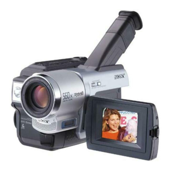
Photo : DCR-TRV130E
For MECHANISM ADJUSTMENT, refer to the
"8mm Video MECHANICAL ADJUSTMENT
MANUAL
861-11).
NTSC model : DCR-TRV130
PAL model
SPECIFICATIONS
DIGITAL VIDEO CAMERA RECORDER
RMT-814
US Model
Canadian Model
Korea Model
Brazilian Model
DCR-TRV130
AEP Model
UK Model
Australian Model
Chinese Model
DCR-TRV130E
E Model
Hong Kong Model
DCR-TRV130/TRV130E
M2000 MECHANISM
IX
M2000 MECHANISM " (9-929-
: DCR-TRV130E
— Continued on next page —
Advertisement
Table of Contents

Related Manuals for Sony HANDYCAM DCR-TRV130E


Summary of Contents for Sony HANDYCAM DCR-TRV130E
- Page 1 DCR-TRV130/TRV130E SERVICE MANUAL SERVICE MANUAL Ver 1.2 2001. 11 Level 2 On the VC-256 board This service manual provides the information that is premised the circuit board replacement service and not intended repair inside the VC-256 board. Therefore, schematic diagram, printed wiring board and electrical parts list of the VC-256 board are not shown.
- Page 2 LES COMPOSANTS IDENTIFÉS PAR UNE MARQUE 0 SUR LES DIAGRAMMES SCHÉMATIQUES ET LA LISTE DES PIÈCES SONT CRITIQUES POUR LA SÉCURITÉ DE FONCTIONNEMENT. NE REMPLACER CES COMPOSANTS QUE PAR DES PIÈSES SONY DONT LES NUMÉROS SONT DONNÉS DANS CE MANUEL OU DANS LES SUPPÉMENTS PUBLIÉS PAR SONY.
-
Page 3: Table Of Contents
Additional Information About video cassettes ·························································· 1-23 About the “InfoLITHIUM” battery pack ····························· 1-24 About i.LINK ······································································· 1-24 Using your camcorder abroad ·············································· 1-25 Maintenance information and precautions ··························· 1-25 TABLE OF CONTENTS Quick Reference Identifying the parts and controls ········································ 1-27 DISASSEMBLY 2-1. - Page 4 Shematic diagram and printed wiring board of the VC-256 board are not shown. Pages from 4-31 to 4-64 are not shown. 4-3. WAVEFORMS ······························································ 4-65 4-4. MOUNTED PARTS LOCATION ································· 4-69 ADJUSTMENTS Before starting adjustment ··············································· 5-2 1-1. Adjusting items when replacing main parts and boards ·· 5-2 5-1.
- Page 5 Switch check (4) ···························································· 5-56 Record of Use check ······················································ 5-56 Record of Self-diagnosis check ····································· 5-57 REPAIR PARTS LIST 6-1. EXPLODED VIEWS ······················································ 6-1 6-1-1. OVERALL SECTION ····················································· 6-1 6-1-2. CABINET (L) SECTION ················································ 6-2 6-1-3. EVF SECTION ································································ 6-3 6-1-4.
-
Page 6: Service Note
POWER SUPPLY DURING REPAIRS In this unit, about 10 seconds after power is supplied (8.4V) to the battery terminal using the service power code (J-6082-223-A), the power is shut off so that the unit cannot operate. These following two methods are available to prevent this. Take note of which to use during repairs. Method 1. -
Page 7: Self-Diagnosis Function
Self-diagnosis Function When problems occur while the unit is operating, the self-diagnosis function starts working, and displays on the viewfinder or LCD or Display window what to do. This function consists of two display; self-diagnosis display and service mode display. Details of the self-diagnosis functions are provided in the Instruction manual. -
Page 8: Self-Diagnosis Code Table
Self-diagnosis Code Table Self-diagnosis Code Block Detailed Function Code Non-standard battery is used. Condensation. Video head is dirty. LOAD direction. Loading does not complete within specified time UNLOAD direction. Loading does not complete within specified time T reel side tape slacking when unloading. S reel side tape slacking when unloading. - Page 9 Self-diagnosis Code Block Detailed Symptom/State Function Code Difficult to adjust focus (Cannot initialize focus.) Zoom operations fault (Cannot initialize zoom lens.) Handshake correction function does not work well. (With pitch angular velocity sensor output stopped.) Handshake correction function does not work well.
-
Page 10: General
DCR-TRV130/TRV130E SECTION 1 This section is extracted from instruction GENERAL manual. (DCR-TRV130E model) - Page 19 1-10...
- Page 20 1-11...
- Page 21 1-12...
- Page 22 1-13...
- Page 23 1-14...
- Page 24 1-15...
- Page 25 1-16...
- Page 26 1-17...
- Page 27 1-18...
- Page 28 1-19...
- Page 29 1-20...
- Page 30 1-21...
- Page 31 1-22...
- Page 32 1-23...
- Page 33 1-24...
- Page 34 1-25...
- Page 35 1-26...
- Page 36 1-27...
- Page 37 1-28...
- Page 38 1-29E...
-
Page 39: Disassembly
The following flow chart shows the disassembly procedure. 2-1. Video light 2-2. LCD section (PD-131 board) 2-3. Front panel section (MI-041 board) 2-4. Cabinet (L) section 2-5. Cabinet (R) section, Control switch block (CF-1000) 2-6. EVF section (VF-129 board) 2-7, Battery panel section (Battery terminal board) 2-8, Lens section 2-9. -
Page 40: Video Light
[CONNECTION OF EQUIPMENTS] Info lithium battery (L series) Adjustment remote commander (RM-95) CPC-jig (J-6082-521-A) NOTE: Follow the disassembly procedure in the numerical order given. 2-1. VIDEO LIGHT 1 Push in the dent inside hole with wire tip. CN1011 Two claws CPC lid 2 Video light AC power... -
Page 41: Lcd Section (Pd-131 Board)
2-2. LCD SECTION (PD-131 BOARD) 4 P cabinet C 2 MI screw 4) (H) 9 PD-131 board, Panel frame 8 Back light Cold cathode fluorescent tube 7 Liquid crystal indicator module [PD-131 BOARD SERVICE POSITION] Info lithium battery (L series) Adjustment remote commander (RM-95) Panel frame (12) -
Page 42: Front Panel Section (Mi-041 Board)
2-3. FRONT PANEL SECTION (MI-041 BOARD) 1 Open the jack cover 3 MI screw 4) (H) 2 Two MI screws 4) (H) 7 Front panel section 2 Microphone (Lch) (2P) 1 Microphone (Rch) (2P) [MI-041 BOARD SERVICE POSITION] FP-263 flexible board (24P) MI-041 board Adjustment remote... -
Page 43: Cabinet (L) Section
2-4. CABINET (L) SECTION 6 Two MI screws [MECHANISM DECK SERVICE POSITION] Note: Use the parts only which can be removed easily from outside of the mechanism deck. 4 MI screw 4) (H) 5 MI screw 4) (H) 7 MI screw Mechanism deck AC power adaptor... -
Page 44: Cabinet (R) Section, Control Switch Block
2-5. CABINET (R) SECTION, CONTROL SWITCH BLOCK (CF-1000) 1 MI screw 4) (H) 4 Claw 2 MI screw 4) (H) 7 Cabinet (R) section 6 FFC-295 flexible flat cable (24P) 5 Harness 3 Three MI screws (PD-110) (20P) 4) (H) 7 Remove the control switch block (CF-1000) in the direction of the arrow A B . -
Page 45: Evf Section (Vf-129 Board)
2-6. EVF SECTION (VF-129 BOARD) 1 FFC-289 flexible flat cable (4P) 3 Finder (S) assembly Rotate it in the direction of the arrow B and remove it in the direction of the arrow C . 2 Two tapping screws (B2 REMOVING THE CRT ASSEMBLY AND VF-129 BOARD 4 High voltage cover... -
Page 46: Battery Panel Section (Battery Terminal Board)
[VF-129, CD-281, MI-041 BOARDS SERVICE POSITION] CD-281 board FP-263 flexible board (24P) MI-041 board Info lithium battery (L series) 2-7. BATTERY PANEL SECTION (BATTERY TERMINAL BOARD) 2 Strap sheet metal (lower) 1 MI screw 3 Battery terminal board Adjustment remote commander (RM-95) 1 Tripod screw 4 MI screw... -
Page 47: Lens Section
2-8. LENS SECTION 5 Claw 4 Two screws lock ace, p2 2-9. VC-256 BOARD 5 FP-258 flexible board 4 Jack cushion 3 Two screws lock ace, p2 2 Flexible board (from lens block)(24P) 1 FP-259 flexible board (14P) 3 Screw lock ace, p2 1 Two screws (M2 2 MD frame B... -
Page 48: Mechanism Deck
[SERVICE POSITION TO CHECK THE VTR SECTION] Connection to Check the VTR Section To check the VTR section, set the VTR to the "Forced VTR power ON" mode. Operate the VTR functions using the adjustment remote commander (with the HOLD switch set in the OFF position). Setting the “Forced VTR Power ON”... - Page 49 [SERVICE POSITION TO CHECK THE CAMERA SECTION] Connection to Check the Camera Section To check the camera section, set the camera to the "Forced camera power ON" mode. Setting the “Forced Camera Power ON” mode 1) Select page: 0, address: 01, and set data: 01. 2) Select page: D, address: 10, set data: 01, and press the PAUSE button of the adjustment remote commander.
-
Page 50: Hinge Section
2-10.MECHANISM DECK 4 Control switch block 1 Screw (FK-1000) lock ace, p2 2 Two claws 2-11.HINGE SECTION 3 Electro luminous 5 Hinge blind, Push switch 1 FP-260 flexible board (16P) 2 Push switch (2P) 4 Three tapping screws (B2 1 Four tapping screws (B2 REMOVING THE MECHANISM DECK 3 Three... -
Page 51: Circuit Boards Location
2-12.CIRCUIT BOARDS LOCATION CD-281 (CCD IMAGER) CONTROL SWITCH BLOCK (CF-1000) MI-041 STEADY SHOT, MIC AMP, IR DRIVE (TRV130 ONLY) VF-129 (B/W EVF) VC-256 CAMERA PROCESS, CAMERA Y/C PROCESS, FOCUS/ZOOM DRIVE, EVR, DV SIGNAL PROCESS, DV INTERFACE, DIGITAL REC/PB AMP, VIDEO OUT, HI CONTROL, CAMERA/MECHA CONTROL, MECHANISM CONTROL, DRUM/CAPSTAN MOTOR DRIVE, AUDIO PROCESS, DC IN, CHARGE, DC/DC CONVERTER... -
Page 52: Flexible Boards Location
2-13.FLEXIBLE BOARDS LOCATION The flexible boards contained in the mechanism deck are not shown. CONTROL SWITCH BLOCK (FK-1000) FFC-289 FP-259 FP-263 CONTROL SWITCH BLOCK (PR-10000) IRIS FLEXIBLE ASSEMBLY 630 ELECTRO LUMINOUS ELEMENT (BACK LIGHT) FP-258 (VIDEO LIGHT, S VIDEO) FFC-295 FP-260 2-14E CONTROL SWITCH BLOCK... -
Page 53: Block Diagrams
SECTION 3 BLOCK DIAGRAMS 3-1. OVERALL BLOCK DIAGRAM (1/5) ( ) : Page No. shown in ( ) indicates the page to refer on the schematic diagram. CD-281 BOARD LENS ASSY IRIS ZOOM MOTOR FOCUS MOTOR IRIS METER NIGHT M904 M905 SHOT ZOOM... -
Page 54: Overall Block Diagram (2/5)
DCR-TRV130/TRV130E 3-2. OVERALL BLOCK DIAGRAM (2/5) ( ) : Page No. shown in ( ) indicates the page to refer on the schematic diagram. VC-256 BOARD(2/4) Y0-Y7 Y0-Y7 OVERALL BLOCK(1/5) (SEE PAGE C0-C3 C0-C3 3-2) HD, VD, OE HD,VD,OE SPCK IR FCS IC3302 CHARACTER... -
Page 55: Overall Block Diagram (3/5)
3-3. OVERALL BLOCK DIAGRAM (3/5) ( ) : Page No. shown in ( ) indicates the page to refer on the schematic diagram. VC-256 BOARD(3/4) (4-50) IC4501 DRP SO,DRP SI,XDRP SCK DIGITAL8 MECHA CONTROL VSP SO,VSP SI,XVSP SCK VSP SO,VSP SI,XVSP SCK SIGNAL PROCESS CONTROL... -
Page 56: Overall Block Diagram (4/5)
DCR-TRV130/TRV130E 3-4. OVERALL BLOCK DIAGRAM (4/5) ( ) : Page No. shown in ( ) indicates the page to refer on the schematic diagram. CONTROL SWITCH BLOCK (CF-1000)(2/2) (SEE PAGE 4-27) S007 CN001 CN1007 DIAL A DIAL B SEL/PUSH EXEC MENU EXEC DIAL FUNCTION... -
Page 57: Overall Block Diagram (5/5)
3-5. OVERALL BLOCK DIAGRAM (5/5) ( ) : Page No. shown in ( ) indicates the page to refer on the schematic diagram. PD-131 BOARD(2/2) R5522 1.5k PANEL R IC5501 PANEL G PANEL B VR,VG,VB DRIVE (4-19) XCS LCD OVERALL IC5502 BLOCK (2/5) -
Page 58: Power Block Diagram (1/2)
DCR-TRV130/TRV130E 3-6. POWER BLOCK DIAGRAM (1/2) ( ) : Page No. shown in ( ) indicates the page to refer on the schematic diagram. TERMINAL PD-131 BOARD (4-19) (4-19) IC5501 IC5502 TIMING DRIVE GENERATOR PANEL 13.3V PANEL 4.75V PANEL -15.3V PANEL 2.8V IC5601 CN5501... -
Page 59: Power Block Diagram (2/2)
3-7. POWER BLOCK DIAGRAM (2/2) ( ) : Page No. shown in ( ) indicates the page to refer on the schematic diagram. VC-256 BOARD BATT SIG BATT/XEXT SW FAST CHARGE DC PACK SW INIT CHARGE ON BATT UNREG VL UNREG V IN MT 4.75V V BATT... -
Page 60: Printed Wiring Boards And Schematic Diagrams
SECTION 4 PRINTED WIRING BOARDS AND SCHEMATIC DIAGRAMS 4-1. FRAME SCHEMATIC DIAGRAM (1/2) M2000 MECHANISM M903 LOADING MOTOR CN4401 LM(-) LM(+) CN4402 FG-PG_COM FG-PG_COM M901 DRUM MOTOR CN3101 SP1(X) XODD(SP1X) SP1(Y) YODD(SP1Y) SP2(X) XEVEN(SP2X) VIDEO HEAD SP2(Y) YEVEN(SP2Y) FE(Y) FE(Y) FE(X) FE(X) CN4403... -
Page 61: Frame Schematic Diagram (1/2)
DCR-TRV130/TRV130E FRAME SCHEMATIC DIAGRAM (2/2) CONTROL SWITCH BLOCK (CF-1000) J001 (HEADPHONES) CN003 SP901 SP(+) SPEAKER SP(-) S901 CN009 (OPEN/CLOSE) OPEN/CLOSE TO FH(1/2) VC-256 BOARD(2/2) FRAME SCHEMATIC DIAGRAM (2/2) D901 LCD 902 CHARACTER DISPLAY BT001 S001-004,006,009 LITHIUM BATTERY 012,013,015,016,018,019, S007 SEL/PUSH EXEC RESET/MENU/TIME/EXPOSURE/ SUPER NIGHT SHOT/END SEARCH/ PD-131 BOARD... - Page 62 4-2. PRINTED WIRING BOARDS AND SCHEMATIC DIAGRAMS THIS NOTE IS COMMON FOR WIRING BOARDS AND SCHEMATIC DIAGRAMS (In addition to this, the necessary note is printed in each block) (For printed wiring boards) (Measuring conditions voltage and waveform) • b: Pattern from the side which enables seeing. •...
- Page 63 DCR-TRV130/TRV130E CD-281 (CCD IMAGER) PRINTED WIRING BOARD — Ref. No. CD-281 Board; 1,000 Series — For printed wiring board • Refer to page 4-69 for parts location. CD-281 (CCD IMAGER) • CD-281 board consists of multiple layers. However, only the sides (layers) A and B are shown. •...
-
Page 64: Steady Shot, Mic Amp, Ir Drive
MI-041 (STEADY SHOT, MIC AMP, IR DRIVE) PRINTED WIRING BOARD — Ref. No. MI-041 Board; 20,000 Series — DCR-TRV130/TRV130E For printed wiring board • Refer to page 4-69 for parts location. • MI-041 board consists of multiple layers. However, only the sides (layers) A and B are shown. -
Page 65: Steady Shot, Mic Amp
DCR-TRV130/TRV130E For Schematic Diagram • Refer to page 4-9 for printed wiring board. MI-041 BOARD(1/2) STEADY SHOT,MIC AMP -REF.NO.:20000 SERIES- XX MARK:NO MOUNT NO MARK:REC/PB MODE R :REC MODE P :PB MODE D752 MA111-(K8)SO. IC751 REMOTE COMMANDER RECEIVER IC751 PNA4S13MO2SO :TRV130 RS-180-T :TRV130E... -
Page 66: Ir Drive
For Schematic Diagram • Refer to page 4-9 for printed wiring board. • Refer to page 4-65 for waveforms. MI-041 BOARD(2/2) NO MARK:REC/PB MODE R :REC MODE IR DRIVE P :PB MODE NO MARK:IR ON/IR OFF MODE -REF.NO.:20000 SERIES- XX MARK:NO MOUNT R3924 L3906 10uH... -
Page 67: Rgb, Timing Generator, Back Light)
DCR-TRV130/TRV130E PD-131 (RGB, TIMING GENERATOR, BACK LIGHT) PRINTED WIRING BOARD — Ref. No. PD-131 Board; 30,000 Series — For printed wiring board • Refer to page 4-69 for parts location. • PD-131 board consists of multiple layers. However, only the sides (layers) A and B are shown. •... - Page 68 DCR-TRV130/TRV130E RGB, TIMING GENERATOR, BACK LIGHT 4-17 4-18 PD-131...
- Page 69 DCR-TRV130/TRV130E For Schematic Diagram • Refer to page 4-15 for printed wiring board. • Refer to page 4-65 for waveforms. PD-131 BOARD(1/2) RGB,TIMING GENERATOR -REF.NO.:30000 SERIES- XX MARK:NO MOUNT NO MARK:REC/PB MODE R :REC MODE P :PB MODE CN5701 REG_GND SE_GND SE_GND TO(2/2)
- Page 70 For Schematic Diagram • Refer to page 4-15 for printed wiring board. PD-131 BOARD(2/2) BACK LIGHT L5601 100uH R5601 -REF.NO.:30000 SERIES- 1800 XX MARK:NO MOUNT NO MARK:REC/PB MODE R :REC MODE P :PB MODE C5603 0.015u BL_REG -0.5 C5607 4.7u C5602 INVERTER DRIVE 3216...
- Page 71 DCR-TRV130/TRV130E VF-129 (B/W EVF) PRINTED WIRING BOARD — Ref. No. VF-129 Board; 1,000 Series — For printed wiring board VF-129 • Refer to page 4-70 for parts location. (B/W EVF) • VF-129 board consists of multiple layers. However, only the sides (layers) A and B are shown. •...
- Page 72 For Schematic Diagram • Refer to page 4-24 for printed wiring board. • Refer to page 4-65 for waveforms. VF-129 BOARD B/W EVF -REF.NO.:1000 SERIES- XX MARK:NO MOUNT NO MARK:REC/PB MODE R :REC MODE P :PB MODE CN901 EVF_4.75V VC-256 BOARD(13/15) CN1006 EVF_GND THROUGH THE FFC-256...
- Page 73 DCR-TRV130/TRV130E CONTROL SWITCH BLOCK(CF-1000) SWITCH,INDICATOR DRIVE XX MARK:NO MOUNT KEY_AD2 KEY_AD3 KEY_AD4 CN001 DIAL_A KEY_AD2 OPEN/CLOSE SW KEY_AD3 DIAL_B KEY_AD4 D_2.8V BL_GND EVER_3.0V LCD_LED_ON R005 XCHARGE_LED_ON LI_3V REG_GND DIAL_A REG_GND VC-256 BOARD(13/15) DIAL_B XHI_RESET CN1007 VTR_UNREG BT001 D_2.8V (THROUGH THE LITHIUM BATTERY FFC-295 FLAT CABLE) EVER_3.0V...
- Page 74 LS-057 (S/T REEL SENSOR), FP-228 (DEW SENSOR), FP-299 (MODE SWITCH), FP-300 (TAPE TOP), FP-302 (TAPE END), FP-301 (TAPE LED) FLEXIBLE BOARDS FP-300 FLEXIBLE (COMPONENT SIDE) 1-680-436- LS-057 BOARD (CONDUCTOR SIDE) S001 REC PROOF FP-299 FLEXIBLE M902 CAPSTAN MOTOR MR SENSOR DEW SENSOR 1-677-049- FP-228...
-
Page 75: Pages From 4-31 To 4-64 Are Not Shown
Schematic diagram and printed wiring board of the VC-256 board are not shown. Pages from 4-31 to 4-64 are not shown. FP-258 (VIDEO LIGHT, S VIDEO) FLEXIBLE BOARD FP-258 FLEXIBLE (VIDEO LIGHT) J201 CN201 DV IN/OUT 1-680-199- FP-258 FLEXIBLE VIDEO LIGHT,S VIDEO LND151 LIGHT VCC LND152... -
Page 76: Waveforms
4-3. WAVEFORMS CD-281 MI-041 BOARD CAMERA REC REC/PB, IR ON IC191 1,2 IC3901 7 6.8Vp-p IC191 3,4 IC3901 ws 6.8Vp-p IC191 7 IC3901 ra 0.6Vp-p IC191 qs “ 4.6Vp-p 105 nsec IC191 qd,qf¢ 6.8Vp-p 105 nsec Q191 E 0.6Vp-p PD-131 BOARD BOARD IC5501 rk... - Page 77 Waveforms and parts location of the VC-256 board are not shown. Pages from 4-66 to 4-68 are not shown.
-
Page 78: Mounted Parts Location
4-4. MOUNTED PARTS LOCATION CD-281 BOARD (SIDE A) MI-041 BOARD (SIDE A) C191 C758 C196 C762 C775 IC191 C784 C791 C794 C799 C800 C808 CD-281 BOARD (SIDE B) C809 C810 C193 C3901 C194 C3902 C195 C3903 C197 C3904 C3905 CN191 A-5 C3906 C3907 L191... - Page 79 DCR-TRV130/TRV130E VF-129 BOARD (SIDE A) C903 R913 C904 R914 C906 R915 C907 R916 C909 R917 C913 R922 R927 CN902 B-1 R928 R929 D901 R930 R931 IC901 R932 L901 RV903 C-2 L903 RV904 D-1 R903 T901 R907 T902 R908 R909 TH901 C-2 R910 R912 W901...
-
Page 80: Adjustments
DCR-TRV130/TRV130E SECTION 5 ADJUSTMENTS... -
Page 81: Before Starting Adjustment
Before starting adjustment 1-1. Adjusting items when replacing main parts and boards. When replacing main parts, adjust the items indicated by Adjustment Adjustment Section Initialization of Initialization of C, D, 8 page data C, D, E, F, 7, 8 page data Initialization of E, F, 7 page data HALL adj. - Page 82 When replacing a board or EEPROM, adjust the items indicated by Adjustment Adjustment Section Initialization of Initialization of C, D, 8 page data C, D, E, F, 7, 8 page data Initialization of E, F, 7 page data HALL adj. Flange back adj.
-
Page 83: Preparations Before Adjustment
5-1. CAMERA SECTION ADJUSTMENT 1-1. PREPARATIONS BEFORE ADJUSTMENT (CAMERA SECTION) 1-1-1. List of Service Tools • Oscilloscope • Color monitor • Regulated power supply • Digital voltmeter Ref. No. Name Filter for color temperature correction (C14) ND filter 1.0 ND filter 0.4 ND filter 0.1 Pattern box PTB-450 Color chart for pattern box... -
Page 84: Preparations
1-1-2. Preparations Note1: For details of how remove the cabinet and boards, refer to “2. DISASSEMBLY”. Note2: When performing only the adjustments, the lens block and boards need not be disassembled. Connect the equipment for adjustments according to Fig. 5-1-4. Connect the adjustment remote commander to CN1011 of VC- 256 board via CPC jig for BX/BK (J-6082-521-A). - Page 85 Note: Use either the AC power adaptor or the Info-LITHIUM battery as the power supply of the CPC jig for BX/BK. AC power adaptor (8.4Vdc) AC-L10 or AC-VQ800 Terminated at 75 Vector scope Adjustment remote commander Color monitor AUDIO VIDEO (Black) (Yellew) Must be connected when...
-
Page 86: Precaution
1-1-3. Precaution 1. Setting the Switch Unless otherwise specified, set the switches as follows and perform adjustments without loading cassette. POWER switch (SS-1000 block) ... CAMERA NIGHT SHOT switch (Lens block) ... OFF LIGHT switch (FK-1000 block) ... OFF DEMO MODE (Menu display) ... OFF DIGITAL ZOOM (Menu display) ... -
Page 87: Initialization Of C, D, E, F, 7, 8 Page Data
When changing the data, copy the data built in the same model. Note: If copy the data built in the different model, the camcorder may not operate. 3) When changing the data, press the PAUSE button of the adjustment remote commander each time when setting new data to write the data in the non-volatile memory. - Page 88 C page Address Remark Initial value 9C to D5 Fixed data-1 Fixed data-2 (Modified data. Copy the data built in the same model.) E1 to E5 Fixed data-1 Fixed data-2 Fixed data-1 Serial No. input F0 to F3 Fixed data-1 Emergency memory address Table.
- Page 89 D page Address Remark Initial value Fixed data-2 (Modified data. Copy the data built in the same model.) 5D to 60 Fixed data-1 Fixed data-2 Fixed data-1 Fixed data-2 (Modified data. Copy the data built in the same model.) 69 to 86 Fixed data-1 Fixed data-2 (Modified data.
-
Page 90: Modification Of E, F, 7 Page Data
When changing the data, copy the data built in the same model. Note: If copy the data built in the different model, the camcorder may not operate. When changing the data, press the PAUSE button of the adjustment remote commander each time when setting new data to write the data in the non-volatile memory. -
Page 91: Page Table
F page Initial value Address Remark NTSC PAL CAP FG duty adj. 65 to 7D Fixed data-1 IR video deviation adj. IR audio deviation adj. IR video carrier freq. adj. 81 to 99 Fixed data-1 Fixed data-2 9B to CC Fixed data-1 Fixed data-2 CE to D3... -
Page 92: Camera System Adjustments
1-3. CAMERA SYSTEM ADJUSTMENTS Before perform the camera system adjustments, check that the specified values of “VIDEO SYSTEM ADJUSTMENTS” are satisfied. 1. HALL Adjustment For detecting the position of the lens iris, adjust AMP gain and offset. Subject Not required Measurement Point Display data of page 1 (Note1) Measuring Instrument... -
Page 93: Flange Back Adjustment (Using Minipattern Box)
Note: The attachment lenses are not used. 2) Install the minipattern box so that the distance between it and the front of the lens of the camcorder is less than 3cm. 3) Make the height of the minipattern box and the camcorder equal. -
Page 94: Flange Back Adjustment (1)
3. Flange Back Adjustment (Using Flange Back Adjustment Chart and Subject More Than 500m Away) The inner focus lens flange back adjustment is carried out automatically. In whichever case, the focus will be deviated during auto focusing/manual focusing. 3-1. Flange Back Adjustment (1) Subject Flange back adjustment chart (2.0 m from the front of the protection... -
Page 95: Flange Back Check
4. Flange Back Check Subject Siemens star (2.0m from the front of the lens) (Luminance : approx. 200 lux) Measurement Point Check operation on TV monitor Measuring Instrument Specified Value Focused at the TELE end and WIDE end. Switch setting: 1) NIGHT SHOT ... -
Page 96: Color Reproduction Adjustment
6. Color Reproduction Adjustment Adjust the color Separation matrix coefficient so that proper color reproduction is produced. Subject Color bar chart (Color reproduction adjustment frame) Measurement Point Video output terminal Measuring Instrument Vectorscope Adjustment Page Adjustment Address 47, 49, D7, D8 Specified Value All color luminance points should settle within each color reproduction frame. -
Page 97: Auto White Balance & Lv Standard Data Input
7. Auto White Balance & LV Standard Data Input Adjust the white balance reference at 3200K, and adjust the normal coefficient of the light value. Subject Clear chart (Color reproduction adjustment frame) Measuring Instrument Adjustment remote commander Adjustment Page Adjustment Address 3C to 41 Note1: This adjustment should be carried out upon completion of “Color reproduction adjustments”. - Page 98 8. Auto White Balance Adjustment Adjust to the proper auto white balance output data. If it is not correct, auto white balance and color reproducibility will be poor. Subject Clear chart (Color reproduction adjustment frame) Filter Filter C14 for color temperature correction Measurement Point Display data of page 1 (Note3)
-
Page 99: White Balance Check
9. White Balance Check Subject Clear chart (Color reproduction adjustment frame) Filter Filter C14 for color temperature correction ND filter 1.0 and 0.4 and 0.1 Measurement Point Video output terminal Measuring Instrument Vectorscope Specified Value Fig. 5-1-12. A to B Switch setting: 1) NIGHT SHOT ... -
Page 100: Angular Velocity Sensor Sensitivity Adjustment
Check that the display data (Note) satisfies the specified value. Processing after Completing Adjustments Order Page Address Data Set the data. Set the data. Move the camcorder, and check that the steady shot operations have been performed normally Procedure Procedure 5-21... -
Page 101: Monochrome Electronic Viewfineder
1-4. MONOCHROME ELECTRONIC VIEWFINEDER SYSTEM ADJUSTMENTS Note: NTSC model: DCR-TRV130 PAL model: DCR-TRV130E 1-4-1. Horizontal Slant Check Mode Playback Signal Alignment tape : For checking system operation (WR5-5ND(NTSC)) (WR5-5CD(PAL)) Monoscope section Specified Value ± 1.5 Adjustment method: 1) Adjust RV904 (BRIGHT) (VF-129 board) so that the CRT can be seen easily and clearly. -
Page 102: Aberration Adjustment
1-4-4. Aberration Adjustment Mode VTR stop Signal Dot pattern Specified Value 2 a1 Adjustment method: Adjust the aberration adjustment ring so that the tracing of the dot satisfies the specified value. If the centering becomes displaced here, perform the centering adjustment from the beginning again. -
Page 103: Vertical Amplitude Adjustment (Vf-129 Board)
1-4-6. Vertical Amplitude Adjustment (VF-129 board) Mode Playback Signal Alignment tape : For checking system operation (WR5-5ND(NTSC)) (WR5-5CD(PAL)) Monoscope section Adjusting Element RV903 Specified Value 10 ± 3% Adjustment method: 1) Adjust RV903 so that the vertical direction over scan becomes 10 ±... -
Page 104: Lcd System Adjustment
1-5. LCD SYSTEM ADJUSTMENT Note 1: The back light (fluorescent tube) is driven by a high voltage AC power supply. Therefore, do not touch the back light holder to avoid electrical shock. Note 2: When replacing the LCD unit, be careful to prevent damages caused by static electricity. -
Page 105: Lcd Initial Data Input (2)
2. LCD Initial Data Input (2) Mode VTR stop Signal No signal Adjustment Page Adjustment Address A0 to B1 Adjusting method: 1) Select page: 0, address: 01, and set data: 01. 2) Select page: D, and input the data in the following table. Note: To write in the non-volatile memory (EEPROM), press the PAUSE button of the adjustment remote commander each time to set the data. -
Page 106: Rgb Amp Adjustment (Pd-131 Board)
4. RGB AMP Adjustment (PD-131 board) Set the D range of the RGB decoder used to drive the LCD to the specified value. If deviated, the LCD screen will become blackish or saturated (whitish). Mode VTR stop Signal No signal Measurement Point Pin 3 of CN5502 (VG) External trigger: Pin 4 of CN5502... -
Page 107: Com Amp Adjustment (Pd-131 Board)
6. COM AMP Adjustment (PD-131 board) Set the common electrode drive signal level of LCD to the specified value. Mode VTR stop Signal No signal Measurement Point Pin 4 of CN5502 (PANEL COM) Measuring Instrument Oscilloscope Adjustment Page Adjustment Address Specified Value A = 5.40 ±... -
Page 108: White Balance Adjustment (Pd-131 Board)
8. White Balance Adjustment (PD-131 board) Correct the white balance. If deviated, the reproduction of the LCD screen may degenerate. Mode VTR stop Signal No signal Measurement Point Check on LCD screen Measuring Instrument Adjustment Page Adjustment Address A8, A9 Specified Value The LCD screen should not be colored. -
Page 109: Mechanism Section Adjustment
5-2. MECHANISM SECTION ADJUSTMENT Mechanism Section adjustments, checks, and replacement of mechanism parts, refer to the separate volume “8mm Video Mechanical Adjustment Manual IX M2000 Mechanism ”. 2-1. ADJUSTMENT REMOTE COMMANDER Connect the adjustment remote commander to CN1011 of VC-256 board via CPC jig for BX/BK (J-6082-521-A). -
Page 110: Tape Path Adjustment
2-4. TAPE PATH ADJUSTMENT 2-4-1. Preparations for Adjustment Clean the tape path face (tape guide, drum, capstan shaft, pinch roller). Connect the adjustment remote commander. Turn on the HOLD switch of the adjustment remote commander. Select page: 3, address: 33, and set data: 08. Connect the oscilloscope to CPC jig for BX/BK. - Page 111 2-4-2. Tape Path adjustment 1) Playback the SW/OL standard tape. (WR5-2D) 2) Turn the tape guide No.3 and No.6 alternately until the waveform becomes flat. (Fig. 5-2-5.) Note: Zenith adjustment screws for the TG3 and TG6 do not need to be adjusted.
-
Page 112: No.7 Guide (Tg7) Adjustment
2-4-3. No.7 Guide (TG7) Adjustment Playback a tape in REV mode. Confirm that tape slack dose not occur in between the guide No.6 (TG6) 1 and capstan 2. If the tape slack is found, turn the height adjustment screw 4 of the Guide No.7 (TG7) 3 until tape slack is removed. -
Page 113: Video Section Adjustment
5-3. VIDEO SECTION ADJUSTMENT 3-1. PREPARATIONS BEFORE ADJUSTMENTS Use the following measuring instruments for video section adjustments. 3-1-1. Equipment to Required 1) TV monitor 2) Oscilloscope (dual-phenomenon, band width above 30 MHz with delay mode) (Unless specified otherwise, use a 10 : 1 probe.) 3) Frequency counter 4) Pattern generator with video output terminal... -
Page 114: Precautions On Adjusting
3-1-2. Precautions on Adjusting Connect the adjustment remote commander to CN1011 of VC- 256 board via CPC jig for BX/BK (J-6082-521-A). To operate the adjustment remote commander, connect the AC power adapter to the DC IN jack of CPC jig for BX/BK, or connect the L series Info-LITHIUM battery to the battery terminal of CPC jig for BX/BK. -
Page 115: Adjusting Connectors
3-1-3. Adjusting Connectors Some of the adjusting points of the video section are concentrated in CN1011 of VC-256 board. Connect the Measuring instruments and the adjustment remote commander via the CPC jig for BX/BK (J-6082-521-A) to CN1011. To operate the adjustment remote commander, connect the AC power adapter to the DC IN jack of CPC jig for BX/BK, or connect the L series Info-LITHIUM battery to the battery terminal of CPC jig for BX/BK. -
Page 116: Alignment Tape
3-1-5. Alignment Tape The following table lists alignment tapes which are available. Use the tape specified in the signal column for each adjustment. If the type of tape to be used for checking operations is not specified, use whichever type. Digital8 alignment tape Name Usage... -
Page 117: System Control System Adjustment
3-2. SYSTEM CONTROL SYSTEM ADJUSTMENT 1. Initialization of C, D, E, F, 7, 8 Page Data If the C, D, E, F, 7, 8 page data is erased due to some reason, perform “1-2. INITIALIZATION OF C, D, E, F, 7, 8 PAGE DATA”, of “5-1. CAMERA SECTION ADJUSTMENT”. - Page 118 Hexa- Hexa- Decimal Decimal Decimal decimal decimal 0000 8192 2000 16384 0100 8448 2100 16640 0200 8704 2200 16896 0300 8960 2300 17152 1024 0400 9216 2400 17408 1280 0500 9472 2500 17664 1536 0600 9728 2600 17920 1792 0700 9984 2700 18176...
-
Page 119: Servo And Rf System Adjustment
3-3. SERVO AND RF SYSTEM ADJUSTMENT Before perform the servo and RF system adjustments, check that the specified value of “27MHz Origin Oscillation Adjustment” of “VIDEO SYSTEM ADJUSTMENT” is satisfied. Adjusting Procedure: REEL FG adjustment Cap FG duty adjustment PLL fo & LPF fo pre-adjustment Switching position adjustment AGC center level APC &... -
Page 120: Pll Fo & Lpf Fo Pre-Adjustment (Vc-256 Board)
3. PLL fo & LPF fo Pre-Adjustment (VC-256 Board) Mode VTR stop Measurement Point Display data of page: 3, address: 03 Measuring Instrument Adjustment remote commander Adjustment Page Adjustment Address 1F, 20, 22, 29 Specified Value The data of page: 3, address: 02 is “00”. The data of page: 3, address: 03 is “00”. -
Page 121: Agc Center Level And Apc & Aeq Adjustment
5. AGC Center Level and APC & AEQ Adjustment 5-1. Preparations before adjustments Mode Camera recording Subject Arbitrary Note: Use a Hi8 MP tape. Adjusting method: Order Page Address Data Set the data. Set the data. Record the camera signal for three minutes. -
Page 122: Processing After Completing Adjustments
5-4. Processing after Completing Adjustments Order Page Address Data Set the data. Set the data. Set the data. Set the data, and press PAUSE button. Set the data. 6. PLL fo & LPF fo Fine Adjustment (VC-256 Board) Procedure Mode Signal Measurement Point Measuring Instrument... -
Page 123: Video System Adjustments
3-4. VIDEO SYSTEM ADJUSTMENTS 1. 27MHz Origin Oscillation Adjustment (VC-256 Board) Set the frequency of the clock for synchronization. If deviated, the synchronization will be disrupted and the color will become inconsistent. Mode Camera Subject Not required Measurement Point FB1502 (Pin qs of IC1501) or Pin qh of IC1502 Measuring Instrument Frequency counter... -
Page 124: S Video Out Y Level Adjustment (Vc-256 Board)
3. S VIDEO OUT Y Level Adjustment (VC-256 Board) Mode VTR stop Signal No signal Measurement Point Y signal terminal of S VIDEO OUT jack (75 terminated) Measuring Instrument Oscilloscope Adjustment Page Adjustment Address Specified Value A = 1000 ± 20mV Adjusting method: Order Page Address Data Set the data. -
Page 125: Video Out Y, Chroma Level Check (Vc-256 Board)
5. VIDEO OUT Y, Chroma Level Check (VC-256 Board) Mode VTR stop Signal No signal Measurement Point Video terminal of AUDIO/VIDEO jack (75 terminated) Measuring Instrument Oscilloscope Specified Value Sync level: A = 286 ± 18mV (NTSC) A = 300 ± 18mV (PAL) Burst level: B = 286 ±... -
Page 126: Ir Transmitter Adjustments (Dcr-Trv130)
(DCR-TRV130) Adjust using the IR receiver jig (J-6082-383-A). Note: If the distance between the IR receiver jig and the camcorder is below 1m, cover the LASER LINK emitter with a ND filter. (For example, when the distance is 30cm to 50cm, cover the LASER LINK emitter with a ND filter 1.0.) -
Page 127: Ir Audio Deviation Adjustment (Mi-041 Board)
3. IR Audio Deviation Adjustment (MI-041 Board) Mode VTR stop Signal Video : Color bar, VIDEO IN jack of DVMC-DA1 Audio : 400Hz, –7.5dBs, AUDIO IN L and R jack of DVMC-DA1 Measurement Point AUDIO L terminal and AUDIO R terminal of IR receiver jig (Terminated at 47k ) Measuring Instrument... -
Page 128: Audio System Adjustments
3-6. AUDIO SYSTEM ADJUSTMENTS [Connecting the measuring instruments for the audio] Connect the audio system measuring instruments in addition to the video system measuring instruments as shown in Fig. 5-3-15. Playback Main unit Video (Yellow) Left (White) AUDIO/ Right VIDEO (Red) (1-249-437-11) Fig. -
Page 129: Service Mode
5-4. SERVICE MODE 4-1. ADJUSTMENT REMOTE COMMANDER The adjustment remote commander is used for changing the calculation coefficient in signal processing, EVR data, etc. The adjustment remote commander performs bi-directional communication with the unit using the remote commander signal line (LANC). The resultant data of this bi-directional communication is written in the non-volatile memory. -
Page 130: Data Process
4-2. DATA PROCESS The calculation of the DDS display and the adjustment remote commander display data (hexadecimal notation) are required for obtaining the adjustment data of some adjustment items. In this case, after converting the hexadecimal notation to decimal notation, calculate and convert the result to hexadecimal notation, and use it as the adjustment data. -
Page 131: Service Mode
4-3. SERVICE MODE Additional note on adjustment Note: After the completion of the all adjustments, cancel the service mode by either of the following ways. 1) After data on page: D is restored, unplug the main power supply and remove the coin lithium battery. ( In this case, date and time and menu setting have been set by users are canceled. -
Page 132: Emg Code (Emergency Code)
2-2. EMG Code (Emergency Code) Codes corresponding to the errors which occur are written in C page, addresses F4, F8 and FC (or F page, addresses 10, 14 and 18). The type of error indicated by the code are shown in the following table. -
Page 133: Msw Code
2-3. MSW Code • The lower parts of the data of C page, addresses F6, FA and FE represent the MSW codes (mode switch mechanism position) when errors occurs. • The upper parts of the data of C page, addresses F6, FA and FE represent, when the mechanism position is to be moved, the MSW codes at the start movement (when moving the loading motor). -
Page 134: Bit Value Discrimination
3. Bit Value Discrimination Bit values must be discriminated using the display data of the adjustment remote commander for the following items. Us the table below to discriminate if the bit value is “1” or “0”. Display on the adjustment remote commander Page bit3 to bit0 discrimination bit7 to bit4 discrimination... -
Page 135: Switch Check (4)
7. Switch check (4) Page 2 Address 60 to 65 Using method: 1) Select page: 2, address: 60 to 65. 2) By discriminating the display data, the pressed key can be discriminated. Address 00 to 0C 0D to 24 SUPER LIGHT (KEY AD0) LASER LINK... -
Page 136: Record Of Self-Diagnosis Check
9. Record of Self-diagnosis check Page 2 Address B0 to C6 Address Self-diagnosis code “Repaired by” code (Occurred 1st time) *1 “Block function” code (Occurred 1st time) “Detailed” code (Occurred 1st time) “Repaired by” code (Occurred 2nd time) *1 “Block function” code (Occurred 2nd time) “Detailed”... -
Page 137: Repair Parts List
6-1. EXPLODED VIEWS NOTE: • -XX, -X mean standardized parts, so they may have some differences from the original one. • Items marked “*” are not stocked since they are seldom required for routine service. Some delay should be anticipated when ordering these items. -
Page 138: Cabinet (L) Section
6-1-2. CABINET (L) SECTION Mechanism deck (See page 6-7 to 6-10) Ref. No. Part No. Description 1-680-203-11 FP-263 FLEXIBLE BOARD * 52 3-065-428-01 FRAME B (10), MD 3-968-729-51 SCREW (M2), LOCK ACE, P2 1-680-199-11 FP-258 FLEXIBLE BOARD * 55 3-065-429-01 FRAME (10), LENS 4-974-725-01 SCREW (M1.7X2.5), P X-3951-227-1 LID (12) ASSY, CASSETTE 3-067-347-01 MI SCREW M2 (H) -
Page 139: Evf Section
6-1-3. EVF SECTION Ref. No. Part No. Description 3-061-794-01 SCREW, LOOSE STOPPER 3-065-481-01 BASE B (12), VF 3-948-339-81 TAPPING X-3950-230-1 HINGE ASSY, VF 3-065-480-01 CABINET LOWER B (12), EVF 3-053-681-01 TALLY, EVF 1-792-454-11 CABLE, FLEXIBLE FLAT (FFC-289) A-7073-838-A VF-129 (N) BOARD, COMPLETE (TRV130) supplied V901 Remarks... -
Page 140: Lens Section
6-1-4. LENS SECTION IC191 Ref. No. Part No. Description 8-848-729-01 DEVICE, LENS LSV-630A X-3949-355-2 IRIS FLEXIBLE ASSY 630 3-713-791-41 SCREW, TAPPING (M1.7X5), P2 3-713-791-51 SCREW, TAPPING (M1.7X3.5), P2 3-056-022-01 TAPPING (B1.7X3.5), HEAD 3-053-827-01 LEVER, IR 3-053-800-01 SPRING, RETAIN 3-053-799-01 GEAR, IR 3-978-981-11 ADAPTOR (FK), CCD FITTING M906 M905... -
Page 141: Cabinet (R) Section
6-1-5. CABINET (R) SECTION : BT001 (Lithium battary) CF-1000 on the mount position. (See page 4-27) The printed wiring board of the Control switch block (CF-1000) on which lithium battery is mounted, is not shown.] Ref. No. Part No. Description 3-948-339-61 TAPPING 3-065-436-01 BLIND (12), HINGE 1-476-425-21 SWITCH BLOCK, CONTROL (CF-1000) -
Page 142: Lcd Section
6-1-6. LCD SECTION Ref. No. Part No. Description 3-067-347-01 MI SCREW M2 (H) 3-065-474-01 CABINET C (12), P * 253 3-058-672-01 CLAMP, HARNESS 3-948-339-31 SCREW, TAPPING 3-065-477-01 COVER C (12), HINGE X-3951-206-1 HINGE (12) ASSY 1-960-975-11 HARNESS (PD-110) 3-065-478-01 COVER M (12), HINGE 4-974-725-01 SCREW (M1.7X2.5), P 1-418-802-11 SWITCH BLOCK, CONTROL (PR-10000) Remarks... -
Page 143: Cassette Compartment Assy, Drum Assy
6-1-7. CASSETTE COMPARTMENT ASSY, DRUM ASSY LS chassis block assembly M901 (See page 6-8) Ref. No. Part No. Description 3-065-932-01 PAN (2 MAIN M1.4X1.6), CAMERA 3-065-895-01 LEVER, REEL RELEASE 3-065-896-01 PLATE, BLIND X-3951-298-1 CASSETTE COMPARTMENT ASSY X-3951-302-1 DAMPER ASSY X-3951-297-1 GEAR ASSY, R DRIVE Mechanical chassis block assembly (See page 6-9 to 6-10) -
Page 144: Ls Chassis Block Assembly
6-1-8. LS CHASSIS BLOCK ASSEMBLY S002 not supplied Q001 H001 LS-057 not supplied FP-301 not supplied FP-302 not supplied FP-300 not supplied Ref. No. Part No. Description 3-065-822-01 RAIL (S), GUIDE 3-947-503-01 SCREW (M1.4) A-7096-416-A BASE (S) BLOCK ASSY, GUIDE A-7096-415-A BASE (T) BLOCK ASSY, GUIDE A-7096-426-A CHASSIS ASSY, LS 3-065-802-01 SPRING, TG7 ARM... -
Page 145: Mechanical Chassis Block Assembly-1
6-1-9. MECHANICAL CHASSIS BLOCK ASSEMBLY-1 M902 Ref. No. Part No. Description A-7096-422-A BASE ASSY, DRUM 3-947-503-01 SCREW (M1.4) 3-065-928-01 SPACER, GROUND 3-065-927-01 GROUND, DRUM 3-065-932-01 PAN (2 MAIN M1.4X1.6), CAMERA 3-067-154-01 SPRING, CAPSTAN 3-065-931-01 RAIL (T2), GUIDE X-3947-398-1 SCREW ASSY, M1.7 PW 3-065-933-01 PAN (2 MAIN 1.4X4.5), CAMERA 1-677-049-11 FP-228 FLEXIBLE BOARD (DEW SENSOR) 1-680-434-11 FP-299 FLEXIBLE BOARD... -
Page 146: Mechanical Chassis Block Assembly-2
6-1-10. MECHANICAL CHASSIS BLOCK ASSEMBLY-2 Ref. No. Part No. Description 3-065-920-01 ARM, HC DRIVE 3-065-913-01 GEAR (4), LD 3-065-914-01 SHEET, COVER 3-065-917-01 GEAR (1), CAM RELAY 3-065-934-01 HLW CUT 0.98X3X0.25 3-065-915-01 GEAR (1), CAM 3-065-878-01 PLATE (S), GUIDE LOCK 3-065-932-01 PAN (2 MAIN M1.4X1.6), CAMERA A-7096-413-A GEAR (S) ASSY, GUIDE Remarks Ref. -
Page 147: Electrical Parts List
6-2. ELECTRICAL PARTS LIST NOTE: • Due to standardization, replacements in the parts list may be different from the parts specified in the diagrams or the components used on the set. • -XX, -X mean standardized parts, so they may have some difference from the original one. - Page 148 MI-041 Ref. No. Part No. Description C3912 1-110-446-11 ELECT CHIP C3913 1-164-668-11 CERAMIC CHIP C3914 1-164-943-11 CERAMIC CHIP C3915 1-164-943-11 CERAMIC CHIP C3916 1-125-837-91 CERAMIC CHIP C3917 1-125-777-11 CERAMIC CHIP C3918 1-162-913-11 CERAMIC CHIP C3919 1-117-863-11 CERAMIC CHIP C3920 1-117-863-11 CERAMIC CHIP C3921 1-162-921-11 CERAMIC CHIP C3922...
- Page 149 Ref. No. Part No. Description R3909 1-216-821-11 METAL CHIP R3912 1-216-819-11 METAL CHIP R3913 1-216-847-11 METAL CHIP R3914 1-216-847-11 METAL CHIP R3915 1-216-818-11 METAL CHIP R3916 1-216-831-11 METAL CHIP R3917 1-216-817-11 METAL CHIP R3919 1-216-823-11 METAL CHIP R3920 1-216-817-11 METAL CHIP R3921 1-216-817-11 METAL CHIP R3922...
- Page 150 PD-131 VC-256 Ref. No. Part No. Description < RESISTOR > R5501 1-216-853-11 METAL CHIP 470K R5503 1-218-895-11 METAL CHIP 100K R5504 1-216-845-11 METAL CHIP 100K R5505 1-216-835-11 METAL CHIP R5506 1-216-826-11 METAL CHIP 2.7K R5507 1-216-841-11 METAL CHIP R5508 1-216-843-11 METAL CHIP R5509 1-216-837-11 METAL CHIP R5510...
- Page 151 Ref. No. Part No. Description A-7073-838-A VF-129 (N) BOARD, COMPLETE (TRV130) ********************************* A-7073-855-A VF-129 (P) BOARD, COMPLETE (TRV130E) ********************************** < CAPACITOR > C901 1-107-854-11 TANTAL. CHIP C902 1-163-038-11 CERAMIC CHIP C903 1-135-145-11 TANTAL. CHIP C904 1-162-965-11 CERAMIC CHIP C905 1-104-752-11 TANTAL. CHIP C906 1-162-638-11 CERAMIC CHIP C907...
- Page 152 Ref. No. Part No. Description A-7094-141-A NP-F330 BATTERY PACK (TRV130E:AEP,UK) A-7094-141-B NP-F330 BATTERY PACK (TRV130:E,HK,KR,BR/TRV130E:HK,E,AUS,CN) X-3949-376-1 CAP (N) ASSY,LENS 3-742-854-01 LID,BATTERY CASE (FOR RMT-814) 3-065-651-11 OPERATING INSTRUCTIONS (ENGLISH) 3-065-651-21 OPERATING INSTRUCTIONS (FRENCH) 3-065-651-31 OPERATING INSTRUCTIONS (SPANISH/PORTUGUESE) (TRV130:E,BR) 3-065-651-41 OPERATING INSTRUCTIONS (TRANDTIONAL CHINESE) (TRV130:E,HK) 3-065-651-51 OPERATING INSTRUCTIONS (KOREAN) 3-065-651-61 OPERATING INSTRUCTIONS (ARABIC)
- Page 153 FOR CAMERA COLOR REPRODUCTION ADJUSTMENT For NTSC model Take a copy of CAMERA COLOR REPRODUCTION FRAME with a clear sheet for use. For PAL model — 179 — DCR-TRV130 DCR-TRV130E...
- Page 154 DCR-TRV130/TRV130E 2001E1600-1 Sony EMCS Co. 9-929-860-32 ©2001.5 — 180 — Published by DI Customer Center...
- Page 155 DCR-TRV130/TRV130E SERVICE MANUAL Level 2 2001. 11 File this supplement with the Service Manual. Subject • This SUPPLEMENT-1 describes the change of the CCD imager of the DCR-TRV130 (NTSC model) from type S to type M. The following contents are added in accordance with this change. CCD BLOCK ASSY VC-256 Board (for service) Note: See page 2 “Discrimination of the CCD imager type”...
- Page 156 DCR-TRV130/TRV130E Discrimination of the CCD imager type Check the following data Data Page Address Type S Discrimination of the lens type 1) Select page: 6, address: 01, set data: 65, and press PAUSE button. 2) Select page: 0, address: 03, and set data: 19. 3) Select page: 1.
- Page 157 SECTION 4. PRINTED WIRING BOARDS AND SCHEMATIC DIAGRAMS 4-2. PRINTED WIRING BOARDS AND SCHEMATIC DIAGRAMS CD-281 BOARD NO MARK:REC/PB MODE CCD IMAGER -REF.NO.:1000 SERIES- XX MARK:NO MOUNT CN191 VC-256 BOARD(1/15) CN1501 THROUGH THE FP-259 FLEXIBLE (SEE PAGE 4-31) CAM_-7.5V CAM_12V CCD OUT SIGNAL PATH VIDEO SIGNAL...
-
Page 158: Adjustments
DCR-TRV130/TRV130E SECTION 5. ADJUSTMENTS Page Before starting adjustment 1-1. Adjusting items when replacing main parts and boards. When replacing main parts, adjust the items indicated by Adjustment Adjustment Section Initialization of Initialization of C, D, 8 page data C, D, E, F, 7, 8 page data Initialization of E, F, 7 page data HALL adj. - Page 159 Page When replacing a board or EEPROM, adjust the items indicated by Adjustment Adjustment Section Initialization of Initialization of C, D, 8 page data C, D, E, F, 7, 8 page data Initialization of E, F, 7 page data HALL adj. Flange back adj.
- Page 160 DCR-TRV130/TRV130E Page Type S 3. F Page Table Note: Fixed data-1: Initialized data. (Refer to “1. Initializing the E, F, 7 Page Data”.) Fixed data-2: Modified data. (Refer to “2. Modification of E, F, 7 Page Data”.) Initial value Address NTSC PAL 00 to 0F 10 to 27...
- Page 161 Page Type S 4. E Page Table Note: Fixed data-1: Initialized data. (Refer to “1. Initializing the E, F, 7 Page Data”.) Fixed data-2: Modified data. (Refer to “2. Modification of E, F, 7 Page Data”.) Address Remark 00 to 03 Fixed data-1 Fixed data-2 58 to 7D...
-
Page 162: Camera System Adjustments
Before perform the camera system adjustments, check that the specified values of “VIDEO SYSTEM ADJUSTMENTS” are satisfied. 0-1. Lens Type Input Distinguish the type of the lens being used for the camcorder, and input data corresponding to the type. Subject Not required... -
Page 163: Auto White Balance Adjustment
Page Type S 8. Auto White Balance Adjustment Adjust to the proper auto white balance output data. If it is not correct, auto white balance and color reproducibility will be poor. Subject Clear chart (Color reproduction adjustment frame) Filter Filter C14 for color temperature correction Measurement Point Display data of page 1 (Note3) -
Page 164: Repair Parts List
Remarks Ref. No. 0 D901 S901 6-1-2. CABINET (L) SECTION (SERVICE) 6-1-4. LENS SECTION IC191 IC191 Sony EMCS Co. — 10 — : Changed portion. : Deleted portion. D901 Part No. Description 1-757-397-21 CABLE, FLEXIBLE FLAT (FFC-295) 3-941-343-21 TAPE (A) -
Page 165: Revision History
Reverse Ver. Date History 2001.01 Official Release 2001.05 Correction 2001.11 Supplement-1 (PV01-032) Revision History Contents — Error correction S.M. correction: Page • The change of the CCD imager of the DCR- TRV130 (NTSC model) from type S to type M. •...