Advertisement
Quick Links
Installation Instructions
CERBERUS PYROTRONICS
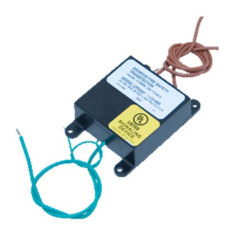
Model CP2297
24 VDC Transient Protector (Optional)
OPERATION
The CERBERUS PYROTRONICS
CP2297 Transient Protector is recommended for
those applications of MXL, MXL-IQ, and IXL that
are susceptible to severe lightning transients.
Model CP2297 provides extra protection to the
basic protection provided in both systems and not
instead of the basic protection. It can be used on
signal lines with nominal voltage of 24 VDC or
less.
In the unlikely event that an overload destroys the
CP2297, the module does not pass power to the
fire alarm control panel; immediate replacement
of the module is then required for continued
operation of the fire alarm panel.
Clearance for No. 6 screws (4)
Figure 1
Mounting Dimensions
Siemens Building Technologies, Inc.
8 Fernwood Road
Florham Park, New Jersey 07932
P/N 315-092355-3
TM
TM
Model
CP2297
Cerberus Division
INSTALLATION
1. See Figure 1 for mounting hole locations.
2. Place the unit within the enclosure near the
location where the protected circuits enter the
panel.
Electrical Connections
(See Figure 2)
Three six inch leads are provided for attaching
the CP2297 to the system.
a. The earth ground lead, located by itself, must
be solidly attached to the fire alarm control
panel earth ground.
NOTE: The earth ground wire must be con-
nected to the FACP metal enclosure.
b. There is no polarity for the remaining two wires
that are attached across the analog detector
loop, NAC loop, or network communication lines.
Figure 2
CP2297 Wiring Diagram
Siemens Building Technologies, Ltd.
50 East Pearce Street
Richmond Hill, Ontario L4B 1B7 CN
Advertisement

Related Manuals for Siemens Cerberus Pyrotronics CP2297


Summary of Contents for Siemens Cerberus Pyrotronics CP2297
-
Page 1: Installation Instructions
Clearance for No. 6 screws (4) Figure 1 Mounting Dimensions Figure 2 CP2297 Wiring Diagram Siemens Building Technologies, Inc. Siemens Building Technologies, Ltd. 8 Fernwood Road 50 East Pearce Street Florham Park, New Jersey 07932 Richmond Hill, Ontario L4B 1B7 CN... - Page 2 Listed below are the modules and terminal numbers to which the low voltage model CP2297 can be connected. The connections for modules that plug into the MOM-4/MOM-2 are made on the MOM-4/MOM-2 screw terminals. INSTALLATION CIRCUIT PROTECTED SYSTEM MODULE INSTRUCTIONS SCREW TERMINALS MXL, MXL-IQ MMB-1...