Table of Contents
Advertisement
Available languages
Available languages
Quick Links
SERVICE MANUAL
Ver 1.0 2001.08
Specifications for SPP-N1023 is different
from that for SPP-N1020 and SPP-N1021.
About SPP-N1023, be sure to refer this
service manual.
Sony Corporation
9-873-245-01
2001H0500-1
Personal Audio Company
C 2001.8
Shinagawa Tec Service Manual Production Group
SPECIFICATIONS
Generales
Banda de frecuencias
Canales de operación
Señal de marcación
Accesorios suministrados
Microteléfono
Fuente de alimentación
Duración de la batería
Dimensiones
Masa
Unidad base
Fuente de alimentación
Tiempo de carga de la batería
Dimensiones
Masa
Design and specifications are subject to change without notice.
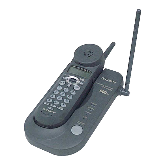
SPP-N1023
902 - 928 MHz
30 canales
Tonos y pulsos (10 pps), seleccionable
Adaptador de alimentación de ca AC-T130
Cables de línea telefónica
Batería BP-T18
Presilla para el cinturón
Soporte mural para la unidad base
Batería BP-T18
Espera: Aprox. 7 días
Conversación: Aprox. 7 horas
Aprox. 55 x 47 x 183 mm (an/al/prf), excluyendo la antena
Antena: Aprox. 34 mm
Aprox. 220 g, incluyendo la batería
cc
9 V del adaptador de alimentación de ca AC-T130
Aprox. 12 horas
Aprox. 127 x 55 x 189 mm (an/al/prf), excluyendo la antena
Antena: Aprox. 153 mm
Aprox. 250 g, excluyendo el soporte mural
CORDLESS TELEPHONE
Mexican Model
Advertisement
Table of Contents

Related Manuals for Sony SPP-N1023


Summary of Contents for Sony SPP-N1023
- Page 1 SPP-N1023 SERVICE MANUAL Mexican Model Ver 1.0 2001.08 Specifications for SPP-N1023 is different from that for SPP-N1020 and SPP-N1021. About SPP-N1023, be sure to refer this service manual. SPECIFICATIONS Generales Banda de frecuencias 902 - 928 MHz Canales de operación 30 canales Señal de marcación...
-
Page 2: Table Of Contents
LINE WITH MARK 0 ON THE SCHEMATIC DIAGRAMS AND IN THE PARTS LIST ARE CRITICAL TO SAFE OPERATION. REPLACE THESE COMPONENTS WITH SONY PARTS WHOSE PART NUMBERS APPEAR AS SHOWN IN THIS MANUAL OR IN SUPPLEMENTS PUB- LISHED BY SONY. -
Page 3: General
útil de la misma habrá expirado, y habrá que reemplazarla. Si aparece “SIN CONEXION” en el Póngase en contacto con su proveedor o con un centro de reparaciones visualizador, acérquese a la unidad autorizado por Sony, y solicite una nueva batería BP-T18 Sony. base. Nota (FLASH) Marque el número de teléfono. -
Page 4: One-Touch Dialing
Para almacenar un número que desee marcar a través de una correcto. • Carácter inicial: Para buscar “SONY”, por ejemplo, presione (7) y después centralita privada (PBX) • El número de teléfono introducido, y (*) y (#) se visualizarán, respectivamente, como mueva hacia abajo la palanca de lanzadera para buscar a través de los... -
Page 5: Setting The Ringer Type
SPP-N1023 Ajuste del tipo de timbre de Comprobación de la lista de Utilización de la lista de llamada identificación de demandantes identificación de demandantes Usted podrá seleccionar el tipo de timbre de llamada del microteléfono entre El teléfono almacenará los datos de las últimas 50 llamadas recibidas. -
Page 6: Disassembly
SPP-N1023 SECTION 2 DISASSEMBLY • This set can be disassembled in the order shown below. 2-1. DISASSEMBLY FLOW Hand Main Board Hand (Rear) Assy Hand (Front) Assy B/S Case BTM Base Main Board Note: Follow the disassembly procedure in the numerical order given. -
Page 7: Hand (Front) Assy
SPP-N1023 2-3. HAND (FRONT) ASSY 1 screw (BTP2.6 × 8) 3 screw (BTP2.6 × 8) 4 two screws (P2 × 5) 6 hand (front) assy 2-4. HAND MAIN BOARD 5 screw (BTP2.6 × 8) 6 RF unit (hand) 8 receiver BKT 4 Remove twelve solders. -
Page 8: B/S Case Btm
SPP-N1023 2-5. B/S CASE BTM 1 three screws (P3 × 12) 2 claw 3 B/S case BTM 2 claw 2-6. BASE MAIN BOARD 6 screw (BTP2.6 × 8) 8 BASE MAIN board 1 Remove solder of lead. 5 Remove solder of lead. -
Page 9: Test Mode
SPP-N1023 SECTION 3 TEST MODE Introduction 4. Data Link Data bits are encoded in manchester format for which bit “0” is The manual test mode can be used for testing the RF and audio represented by 500 µs low and 500 µs high while bit “1” by 500 sections of the base unit and handset. - Page 10 SPP-N1023 3. Key Definition 4. Data Link Data bits are encoded in manchester format for which bit “0” is represented by 500 µs high and 500 µs low while bit “1” by 500 Operation: Set combo to inactive mode. µs low and 500 µs high.
- Page 11 SPP-N1023 Frequency Allocation Tables Base Unit Frequencies: Handset Frequencies: Transmit Receive RX LO Transmit Receive RX LO Channel Channel Frequency Frequency Frequency Frequency Frequency Frequency 902.30 MHz 925.05 MHz 935.75 MHz 925.05 MHz 902.30 MHz 891.60 MHz 903.35 MHz 926.10 MHz 936.80 MHz...
- Page 12 SPP-N1023 MEMO...
-
Page 13: Diagrams
SPP-N1023 SECTION 4 DIAGRAMS 4-1. BLOCK DIAGRAM – BASE UNIT Section – RF UNIT LINE TRANSFORMER AF AMP BUFFER LINE LINE TX (FOR TX) U2 (1/4) FREQUENCY SHIFT KEYING DEMODULATOR HOOK ON/OFF RX DATA RX DATA AF AMP RLL DATA... -
Page 14: Block Diagram - Handset Section
SPP-N1023 4-2. BLOCK DIAGRAM – HANDSET Section – RF UNIT • SIGNAL PATH : TX TX DATA 29 TX DATA : RX 14 PLL EN PLL EN 15 PLL CLK LCD1 PLL CLK LIQUID CRYSTAL PLL I2C DATA 16 PLL I2C DATA... -
Page 15: Note For Printed Wiring Boards And Schematic Diagrams
SPP-N1023 • Waveforms 4-3. NOTE FOR PRINTED WIRING BOARDS AND SCHEMATIC DIAGRAMS – BASE MAIN Board – – HAND MAIN Board – Note on Printed Wiring Board: Note on Schematic Diagram: 1 U4 qh (XOUT) qa U2 3 (XOUT) • All capacitors are in µF unless otherwise noted. pF: µµF •... -
Page 16: Printed Wiring Board - Base Main Board
SPP-N1023 4-4. PRINTED WIRING BOARD – BASE MAIN Board – BASE MAIN BOARD LINE TRANSFORMER CHARGE TERMINAL LINE – DC IN 9V HANDSET LED1 LED6 LED2 LOCATOR LED3 CHARGE LINE POWER NEW CALL UNIT • Semiconductor Location Ref. No. Location Ref. -
Page 17: Schematic Diagram - Base Main Board
SPP-N1023 4-5. SCHEMATIC DIAGRAM – BASE MAIN Board – • • See page 15 for Waveforms. See page 15 for IC Block Diagram. MESSAGE-LED The components identified by mark 0 or dotted line with mark 0 are critical for safety. -
Page 18: Printed Wiring Board - Hand Main Board
SPP-N1023 4-6. PRINTED WIRING BOARD – HAND MAIN Board – • Semiconductor Location Ref. No. Location CHARGE TERMINAL –... -
Page 19: Schematic Diagram - Hand Main Board
SPP-N1023 4-7. SCHEMATIC DIAGRAM – HAND MAIN Board – • See page 15 for Waveforms. -
Page 20: 4-8. Ic Pin Function Description
SPP-N1023 4-8. IC PIN FUNCTION DESCRIPTION • BASE MAIN BOARD U4 TMP86CM25F-3GB1 (SYSTEM CONTROLLER) • HAND MAIN BOARD U2 TMP87C807U-3GB2 (SYSTEM CONTROLLER) Description Pin No. Pin Name Pin No. Pin Name Description CIDSCL Caller-ID clock signal output to the PCC318 (U3) —... -
Page 21: Exploded Views
SPP-N1023 SECTION 5 EXPLODED VIEWS NOTE: • -XX and -X mean standardized parts, so they • Items marked “*” are not stocked since they may have some difference from the original are seldom required for routine service. Some one. delay should be anticipated when ordering •... -
Page 22: 5-2. Base Set Section
SPP-N1023 5-2. BASE SET SECTION supplied Ref. No. Part No. Description Remark Ref. No. Part No. Description Remark 3-041-534-01 FOOT, RUBBER 3-236-289-01 B/S CASE TOP 3-234-967-01 B/S CASE BTM 3-233-543-01 STOPPER, ANT * 53 A-3178-044-A BASE MAIN BOARD, COMPLETE 3-230-068-01 HOOK HANGER... -
Page 23: Electrical Parts List
SPP-N1023 SECTION 6 ELECTRICAL PARTS LIST BASE MAIN NOTE: • Due to standardization, replacements in the • Items marked “*” are not stocked since they The components identified by mark 0 or dotted line with mark parts list may be different from the parts speci- are seldom required for routine service. - Page 24 SPP-N1023 BASE MAIN HAND MAIN Ref. No. Part No. Description Remark Ref. No. Part No. Description Remark < RESISTOR > 1-216-833-11 METAL CHIP 1/16W 1-216-827-11 METAL CHIP 3.3K 1/16W 1-216-797-11 METAL CHIP 1/16W 1-216-837-11 METAL CHIP 1/16W 1-216-818-11 METAL CHIP...
- Page 25 SPP-N1023 HAND MAIN Ref. No. Part No. Description Remark Ref. No. Part No. Description Remark 1-107-826-11 CERAMIC CHIP 0.1uF 1-216-798-11 METAL CHIP 1/16W 1-163-251-11 CERAMIC CHIP 100PF 1-216-845-11 METAL CHIP 100K 1/16W 1-216-845-11 METAL CHIP 100K 1/16W 1-162-923-11 CERAMIC CHIP...
- Page 26 SPP-N1023 Ref. No. Part No. Description Remark Ref. No. Part No. Description Remark ************** HARDWARE LIST ************** 7-685-103-19 SCREW +P 2X5 TYPE2 NON-SLIT 7-685-534-19 SCREW +BTP 2.6X8 TYPE2 N-S 7-685-547-19 SCREW +BTP 3X10 TYPE2 N-S 7-685-648-79 SCREW +P 3X12 TYPE2 NON-SLIT...
- Page 27 SPP-N1023 MEMO...
- Page 28 SPP-N1023 REVISION HISTORY Clicking the version allows you to jump to the revised page. Also, clicking the version at the upper right on the revised page allows you to jump to the next revised page. Ver. Date Description of Revision...