Advertisement
Quick Links
Installation Instructions
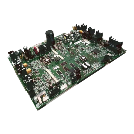
Model MMB-3
Main Control Board
OPERATION
The Model MMB-3 board from Siemens Industry,
Inc., in each MXL System controls operations
and monitors input device identity, network
communication, and operator commands that are
entered through the MKB Annunciator/ Key-
board. The MMB-3 also provides two analog loop
driver circuits. Each ALD-2I loop can be used as
Class B or Class A and can monitor and control
up to 60 intelligent devices as well as program-
mable device relays. The MMB-3 module can be
programmed and upgraded in the field. It is
equipped with two programmable Class B (Style
Y) or Class A (Style Z) notification appliance
circuits. Each circuit can activate up to 1.5 amps
of audible or visual notification appliances. The
MMB-3 has a user-defined Style 4 or Style 7
MNET communication port.
The module also has auxiliary relays for the
external monitoring of Common System Alarm,
Common System Trouble, and Common Supervi-
sory conditions. The Common Supervisory relay
is user programmable.
The MMB-3 includes a built-in battery charger
and transfer circuit. The charger is microproces-
sor controlled and incorporates a brownout circuit
that switches the System to standby batteries
during the loss or reduction of the primary source
AC.
The System can display the real time battery
voltage, the AC voltage, and the charger current
on the MKB display. It also has a 1 amp, 24 VDC
output that powers CZM-1/-1B6 modules.
Siemens Industry, Inc.
Building Technologies Division
Florham Park, NJ
P/N 315-048860-7
For additional information on the MXL/MXLV
System, refer to the MXL/MXLVManual,
P/N 315-092036.
INSTALLATION
Remove all system power before installation,
first battery and then AC. (To power up, connect
the AC first, then the battery.)
Installing the MMB-3 Board
Unpack the MMB-3. Inspect the module, looking
for such things as integrated circuits (ICs) not
firmly seated in their sockets, bent IC pins,
connectors not properly installed, dirt, packing
material on the board, etc.
The MMB-3 includes the following installation kits:
M
M
B
3 -
C
a
b
e l
K
t i
P (
N /
5
4
5
6 -
4
9
0
3
) 5
F
o
r u
#
1
0
n
u
s t
T
h
e r
e
r
s e
t s i
r o
a
s s
e
m
i l b
s e
B
t a
e t
y r
c
a
b
e l
i w
h t
i w
e r
M
M
B
3 -
H
P (
N /
5
4
C
o
n
e t
n
s t
O
n
e
3
p -
o
t i s
o i
n
e r
m
o
a v
b
e l
c s
e r
w
S
x i
4
p -
o
t i s
o i
n
e r
m
o
a v
b
e l
c s
e r
w
O
n
e
9
p -
o
t i s
o i
n
e r
m
o
a v
b
e l
c s
e r
w
To install the MMB-3:
1. Place the MMB-3 with the mounting bracket
over the four standoffs on the MBR-MP
mounting plate in the upper left portion of the
backbox (See Figure 1).
Siemens Building Technologies, Ltd.
Fire Safety & Security Products
2 Kenview Boulevard
Brampton, Ontario
L6T 5E4 Canada
a
d r
w
a
e r
K
t i
5
6 -
4
9
0
3
) 6
U
s
e
d
F
r o
t
r e
m
n i
l a
b
o l
k c
T
B
9
t
r e
m
n i
l a
b
o l
c
s k
T
B
, 1
, 2
, 3
, 5
, 6
t
r e
m
n i
l a
b
o l
k c
T
B
4
7
Advertisement

Related Manuals for Siemens MMB-3


Summary of Contents for Siemens MMB-3
- Page 1 The The MMB-3 includes the following installation kits: MMB-3 has a user-defined Style 4 or Style 7 MNET communication port. The module also has auxiliary relays for the external monitoring of Common System Alarm,...
- Page 2 BACKBOX MBR-MP Figure 1 Installing the MMB-3 NAC1 DO NOT USE MPS-6 MPS-12 NAC2 BATTERY MOM-4 15 AMP MPS-6 8 AMP POWER TO MOM-4 CZM-1 2 AMP MAX. BATTERY CHARGER POWER 5 AMP BATTERY 2 AMP ALD-2I CZM-1 POWER LOOP 2...
-
Page 3: Important Note
2. Secure in place using the hardware provided. Real Time Clock The second jumper on the MMB-3 is P17 which Be sure the screws and nuts are tight, as they pro- must be set for the real time clock to operate vide the earth ground connection for the MMB-3. - Page 4 MMB-3. Connect TB9, 1 and 2 on the jumpers shown in Figure 4 are optional. They are MMB-3 to TB6, 1 and 2 on the MOM 4. not required if the proper settings are made in Refer to Figure 3 for the wiring diagram.
- Page 5 T-TAPPING DEVICE ALLOWED T-TAPPING ALLOWED JUMPERS ARE OPTIONAL FOR MMB-3. REFER TO CSG-M REV. 17.01 *OPERATES IN FULL COMFORMITY WITH STYLE 4 **OPERATES IN FULL COMFORMITY WITH STYLE 6 FOR CONFIGURATION. Positive and negative ground fault detected at <40K ohms for TB2 (1-4) and TB3 (1-4).
-
Page 6: Notification Appliance Circuits
(STYLE Y) TB6 TB7 NOTIFICATION APPLIANCES — RES EOL ASSEMBLY 2.2K,1/2W — P/N 140-049098 — — § — OPTIONAL CLASS B WIRING (MMB-3 ONLY) § — (STYLE Y) TB6 TB7 § — § — RES EOL ASSEMBLY 2.2K,1/2W P/N 140-049098... -
Page 7: Electrical Ratings
Common Alarm Relay Style 4 Network (MNET) The common alarm relay changes state when- The MMB-3 provides a Style 4 MNET network for ever a fire alarm is detected. The relay is rated connection to remote power supplies (PSR-1) 2A, 30 VDC/120 VAC resistive. See Figure 8 for and annunciators (MOI-1/7, RCC). - Page 8 PSR-1 PSR-1 NETWORK SET "MMB-3 MNET STYLE SET "MMB-3 MNET STYLE 7" NETWORK TO "NO" IN THE CSGM. 7" TO "YES" IN THE CSGM. EOLR 120 OHMS, EOLR 120 OHMS, 1/4W, 5% 1/4W, 5% P/N 140-820150 P/N 140-820150 18 AWG MIN...