Bosch B6512 Installation Manual
Hide thumbs
Also See for B6512:
- Installation manual (143 pages) ,
- Quick user manual (56 pages) ,
- Operation manual (224 pages)
Table of Contents
Advertisement
Quick Links
Download this manual
See also:
Quick User Manual
Advertisement
Table of Contents

Related Manuals for Bosch B6512


Summary of Contents for Bosch B6512
- Page 1 Control Panels B6512/B5512/B4512/B3512 (B5512E/B4512E/B3512E) Installation Manual...
-
Page 3: Table Of Contents
1.2.1 Lightning 1.2.2 Power Introduction About documentation 2.1.1 Related documentation Bosch Security Systems, Inc. product manufacturing dates System overview Parts list Control panel capacities Installation checklist Control panel installation Installing the enclosure and wiring label Installing the control panel 5.2.1 Earth ground 5.2.2... - Page 4 B308 octo-output module 11.1.1 SDI2 address settings 11.1.2 Supervision 11.1.3 Installation and control panel wiring (B308) On-board points 12.1 Point sensor loops 12.1.1 Single EOL (and no EOL) resistor circuit style 2018.07 | 16 | F.01U.287.180 Installation Manual Bosch Security Systems, Inc.
- Page 5 2-wire smoke wiring (D125B) 18.5 Notification appliance circuit wiring 18.6 SDI2 devices general system wiring 18.6.1 SDI2 bus wiring recommendations 18.7 Wiring label Approved applications 19.1 Optional compatible equipment 19.1.1 Burglar applications Bosch Security Systems, Inc. Installation Manual 2018.07 | 16 | F.01U.287.180...
- Page 6 20.3 [3] Diags menu 20.3.1 [1] Wireless 20.3.2 [2] Network menu 20.3.3 [3] Cellular menu 20.3.4 [4] IP Camera 20.3.5 [5] Cloud 20.4 [4] Service Bypass (Serv Byp) menu 2018.07 | 16 | F.01U.287.180 Installation Manual Bosch Security Systems, Inc.
- Page 7 SDI2 address information 22.2.3 Device numbers (zzz, dddd) 22.2.4 Communication Trouble device numbers (zzzz) 22.2.5 Special User IDs (uuuu, iiii) 22.2.6 Keypad alarm virtual point numbers (ppp, pppp) 22.3 AutoIP Bosch Security Systems, Inc. Installation Manual 2018.07 | 16 | F.01U.287.180...
-
Page 8: Certifications, Approvals, Listings, And Safety
Listed for Control Panel Standard - Features for False Alarm Reduction ANSI/SIA CP-01-2010. 1.1.4 Department of Defense (DoD) The B6512/B5512/B4512/B3512 control panels were granted approval for Department of Defense (DoD) installations in Sensitive Compartmented Information Facilities (SCIF). 1.1.5 Department of Energy This control panel operates on a transformer that has been reviewed by a third party and deemed to be compliant to the Department of Energy, U.S. -
Page 9: Federal Communications Commission (Fcc) Rules
Part 68 The B430 module by Bosch Security Systems, Inc. is registered with the Federal Communication Commission (FCC) under Part 68, for connection to the public telephone system using an RJ31X or RJ38X phone line connection jack installed by the local telephone company. -
Page 10: Safety
Route telephone, SDI2 bus wiring, and sensor loop wiring away from any AC conductors, including the transformer wire. AC wiring can induce noise and low level voltage into adjacent wiring. 2018.07 | 16 | F.01U.287.180 Installation Manual Bosch Security Systems, Inc. - Page 11 Routine heavy discharges can lead to premature battery failure. Notice! Use sealed lead acid batteries only The charging circuit is calibrated for lead-acid batteries. Do not use gel-cell or NiCad batteries. Bosch Security Systems, Inc. Installation Manual 2018.07 | 16 | F.01U.287.180...
-
Page 12: Introduction
These indicate a hazardous situation which, if not avoided, could result in death or serious injury. Copyright This document is the intellectual property of Bosch Security Systems, Inc. and is protected by copyright. All rights reserved. Trademarks All hardware and software product names used in this document are likely to be registered trademarks and must be treated accordingly. -
Page 13: Bosch Security Systems, Inc. Product Manufacturing Dates
Located on the documentation CD shipped with the module. Bosch Security Systems, Inc. product manufacturing dates Use the serial number located on the product label and refer to the Bosch Security Systems, Inc. website at http://www.boschsecurity.com/datecodes/. The following image shows an example of a product label and highlights where to find the manufacturing date within the serial number. - Page 14 | Introduction Control Panels 2018.07 | 16 | F.01U.287.180 Installation Manual Bosch Security Systems, Inc.
-
Page 15: System Overview
Control panels ship assembled from the factory with the following parts: Literature – Control Panels (B6512/B5512/B4512/B3512) UL Installation Manual – Control Panels (B6512/B5512/B4512/B3512) Operation Manual – Control Panels (B6512/B5512/B4512/B3512) SIA Quick Reference Guide – Control Panels (B6512/B5512/B4512/B3512) Documentation CD – Enclosure Wiring Label (B6512/B5512/B4512/B3512) HW pack –... -
Page 16: Installation Checklist
Install, operate, test, and maintain this device according to the control panel Installation and System Reference Guide. Failure to follow these procedures may cause the device not to function properly. Bosch Security Systems Inc. is not responsible for any devices that are improperly installed, tested, or maintained. -
Page 17: Control Panel Installation
Pull the wires into the enclosure through the knockouts. Position the supplied enclosure wiring label on the inside of the enclosure door. Installing the control panel Identify the control panel mounting location in the enclosure. Bosch Security Systems, Inc. Installation Manual 2018.07 | 16 | F.01U.287.180... - Page 18 If you install a B12, rest the hook tabs on the mounting plate hooks within the enclosure. Secure the lock-down tab to the plate mounting hole with the screw provided. 2018.07 | 16 | F.01U.287.180 Installation Manual Bosch Security Systems, Inc.
-
Page 19: Earth Ground
You can use interconnect or terminal wiring to connect devices to the control panel. Using terminal wiring in parallel Notice! Wire size For terminal wiring, use 18 AWG to 22 AWG (1.0 mm to 0.6 mm) wire. Bosch Security Systems, Inc. Installation Manual 2018.07 | 16 | F.01U.287.180... - Page 20 7 COM 8 BATTERY OUTPUT A - 12 V + NO C NC COM AUX 18VAC + BAT - PWR A B COM OUTPUT A B COM B COM 2018.07 | 16 | F.01U.287.180 Installation Manual Bosch Security Systems, Inc.
-
Page 21: Power Supply
Connect the other end to the negative (-) side of the battery. Connect the red battery lead to BAT+. Connect the other end to the positive (+) side of the battery. Bosch Security Systems, Inc. Installation Manual 2018.07 | 16 | F.01U.287.180... - Page 22 3 ᅳ 0.25 in (6.4 mm) minimum 4 ᅳ Battery terminals. BAT- is non-power limited 5 ᅳ Battery wires 6 ᅳ 12 V sealed lead-acid rechargeable battery (D126/D1218) 7 ᅳ Sensor loop wires 2018.07 | 16 | F.01U.287.180 Installation Manual Bosch Security Systems, Inc.
-
Page 23: Battery Maintenance
For Burglar applications, an additional 2 A of alarm power is available, allowing 2 A of standby current and up to 4 A of alarm current. The control panels support the following number of B520 modules: – B6512. 4 Bosch Security Systems, Inc. Installation Manual 2018.07 | 16 | F.01U.287.180... -
Page 24: Sdi2 Address Settings
Tighten the supplied mounting screws. Wiring to earth ground To help prevent damage from electrostatic charges or other transient electrical surges, connect the system to earth ground before making other connections. 2018.07 | 16 | F.01U.287.180 Installation Manual Bosch Security Systems, Inc. - Page 25 PWR A B COM PWR A B COM PWR A B COM Callout ᅳ Description 1 ᅳ Control panel 2 ᅳ B520 Auxiliary Power Supply Module 3 ᅳ Terminal strip wiring Bosch Security Systems, Inc. Installation Manual 2018.07 | 16 | F.01U.287.180...
-
Page 26: Powered Device And Battery Wiring
You must wire BATT 1. You must wire BATT 2 if you configure the B520 for two batteries. When you use BATT 2, both batteries must have the same rating. Maximum standby power cannot exceed 36 Ah. 2018.07 | 16 | F.01U.287.180 Installation Manual Bosch Security Systems, Inc. - Page 27 1 ᅳ B520 Auxiliary Power Supply Module 2 ᅳ Battery 2 (BATT 2) - (12 V nominal lead acid) 3 ᅳ Battery 1 (BATT 1) - (12 V nominal lead acid) Bosch Security Systems, Inc. Installation Manual 2018.07 | 16 | F.01U.287.180...
-
Page 28: Telephone Communications
12. Notification The B430 module by Bosch Security Systems, Inc. is registered with the Federal Communication Commission (FCC) under Part 68, for connection to the public telephone system using an RJ31X or RJ38X phone line connection jack installed by the local telephone company. -
Page 29: Diagnostic Leds
After installation, make sure that the control panel: – Seizes the line – Gets a dial tone – Reports correctly to the receiver – Releases the telephone line to the in-house telephone system Bosch Security Systems, Inc. Installation Manual 2018.07 | 16 | F.01U.287.180... -
Page 30: Telephone Line Monitor
The called party must go on hook (hang up) for a fixed interval before a dial tone is available for a new call. This interval varies with telephone company equipment. Control panel 2018.07 | 16 | F.01U.287.180 Installation Manual Bosch Security Systems, Inc. -
Page 31: Communication Failure
One hour after a COMM FAIL event, the control panel attempts to send a COMM RSTL event. If a communication failure still occurs, the keypad trouble sounds again. Bosch Security Systems, Inc. Installation Manual 2018.07 | 16 | F.01U.287.180... -
Page 32: Ip Communications
3. If the control panel does use the Ethernet for IP communication, power down the control panel and remove the Ethernet cable that connects the control panel to the network. 2018.07 | 16 | F.01U.287.180 Installation Manual Bosch Security Systems, Inc. -
Page 33: On-Board Ethernet Diagnostic Leds
Flash pattern Function Communicating at 100 Mb. On Steady Communicating at 10 Mb. Tab. 8.2: 100BASE-T LED descriptions Flash pattern Function Plugged into an Ethernet network. On Steady Communication in progress. Bosch Security Systems, Inc. Installation Manual 2018.07 | 16 | F.01U.287.180... -
Page 34: Conettix Plug-In Cellular Modules
With a B426 installed, several services become available to the control panel. Any break in the Ethernet connection to a supervised B426 results in a system fault at the keypads indicating Open Cable trouble. 2018.07 | 16 | F.01U.287.180 Installation Manual Bosch Security Systems, Inc. -
Page 35: Installation And Control Panel Wiring (B426)
Use either the terminal strip wiring or interconnect wiring to the control panel. Do not use both. When you connect multiple modules, you can combine terminal strip and interconnect wiring connectors in parallel. Bosch Security Systems, Inc. Installation Manual 2018.07 | 16 | F.01U.287.180... -
Page 36: Diagnostic Leds
Connect the Ethernet cable to the RJ-45 network jack. 8.3.5 Diagnostic LEDs The module has the following on-board LEDs to assist with troubleshooting: – Heartbeat (system status). – RX (receive). – TX (transmit). 2018.07 | 16 | F.01U.287.180 Installation Manual Bosch Security Systems, Inc. - Page 37 100Mb (green) LED pattern Function No Ethernet link 10Base-T link On Steady 10Base-T activity Flashing 100Base-TX link On Steady On Steady 100Base-TX activity On Steady Flashing Tab. 8.6: Ethernet Link LEDs descriptions Bosch Security Systems, Inc. Installation Manual 2018.07 | 16 | F.01U.287.180...
-
Page 38: Local Programming
Make sure that there is enough power for the module and the other powered devices that you want to connect to the system. Refer to On-board outputs, page 49. 2018.07 | 16 | F.01U.287.180 Installation Manual Bosch Security Systems, Inc. -
Page 39: Diagnostic Leds
The module includes the following on-board LEDs to assist with troubleshooting: – Heartbeat (system status) – RX (receive) – TX (transmit) The plug-in module also includes LEDs for troubleshooting and status. Bosch Security Systems, Inc. Installation Manual 2018.07 | 16 | F.01U.287.180... -
Page 40: Compatible Receivers For Ip Communication
When you configure the control panel to report in Contact ID format, the Conettix central station receiver/gateway and the D6200 Receiver programming software might require an update. Review the following table to decide whether the Conettix needs an update. 2018.07 | 16 | F.01U.287.180 Installation Manual Bosch Security Systems, Inc. - Page 41 Receiver/Gateway CPU version D6200 version Conettix D6600 Communications Receiver/Gateway 01.11.00 2.20 (with D6641 line cards installed only) Conettix D6100IPv6 Communications Receiver/Gateway 61.11.00 2.20 Conettix D6100i Communications Receiver/Gateway 61.11.00 2.20 Bosch Security Systems, Inc. Installation Manual 2018.07 | 16 | F.01U.287.180...
-
Page 42: Keypads, Keyswitches, Keyfobs And Transmitters
The keypad includes fire status indicators, burg indicators, and fire and burg function keys. 2018.07 | 16 | F.01U.287.180 Installation Manual Bosch Security Systems, Inc. -
Page 43: B921C Two-Line Capacitive Keypad With Inputs
Shortcuts menu. Use RPS or the Installer Services Portal programming tool (available in Europe, Middle East, Africa, and China) to create and assign shortcuts and custom functions. Bosch Security Systems, Inc. Installation Manual 2018.07 | 16 | F.01U.287.180... -
Page 44: Address Settings
Use a maximum of 7500 ft (2286 m) of 22 AWG (0.65 mm) wire for all devices connected to the SDI2 bus combined. 2018.07 | 16 | F.01U.287.180 Installation Manual Bosch Security Systems, Inc. -
Page 45: Sensor Loops Overview And Wiring (B921C/B942/B942W Only)
The terminal strip supports 12 to 22 AWG (0.65 to 2 mm) wires. 1COM2 3COM4 Figure 9.1: Keypad inputs wiring (B921C shown) Callout ᅳ Description 1 ᅳ Keypad terminal strip 2 ᅳ Sensor loop 3 ᅳ 1 kΩ EOL resistor (P/N: F01U026703) Bosch Security Systems, Inc. Installation Manual 2018.07 | 16 | F.01U.287.180... -
Page 46: Output Wiring (B942/B942W Only)
For momentary keyswitches, connect the EOL resistor at the keyswitch point so that when the keyswitch operates, it shorts the resistor. An open on the circuit causes an alarm if the area is on (armed) and a trouble if it is off (disarmed). 2018.07 | 16 | F.01U.287.180 Installation Manual Bosch Security Systems, Inc. -
Page 47: Radion Keyfobs And Inovonics Pendant Transmitters
The control panel supports one RADION keyfob or one Inovonics pendant transmitter for each user the control panel supports. – B6512. Up to 10 wireless RADION keyfobs or 100 Inovonics pendant transmitters. – B5512. Up to 50 wireless RADION keyfobs or 50 Inovonics pendant transmitters. - Page 48 Africa, and China), you can assign two custom functions to a RADION keyfob FB, allowing a user to initiate the functions wirelessly. For more information, refer to RPS Help or the Installer Services Portal programming tool Help. 2018.07 | 16 | F.01U.287.180 Installation Manual Bosch Security Systems, Inc.
-
Page 49: On-Board Outputs
The default configuration for Output A makes it a powered output providing alarm power. Use OUTPUT PARAMETERS in RPS or in the Installer Services Portal programming tool (available in Europe, Middle East, Africa, and China) to configure programmable outputs. Bosch Security Systems, Inc. Installation Manual 2018.07 | 16 | F.01U.287.180... -
Page 50: Open Collector Outputs
2 ᅳ D134 Dual Relay Module Use OUTPUT PARAMETERS in RPS or in Installer Services Portal programming tool (available in Europe, Middle East, Africa, and China) to configure programmable outputs. 2018.07 | 16 | F.01U.287.180 Installation Manual Bosch Security Systems, Inc. -
Page 51: Off-Board Outputs
Parameters in RPS Help or in the Installer Services Portal programming tool (available in Europe, Middle East, Africa, and China) Help. The control panels provide up to the following number of modules: – B6512. 9 (72 outputs) – B5512. 5 (40 outputs) –... -
Page 52: Installation And Control Panel Wiring (B308)
B COM R Y G B PWR A B COM PWR A B COM Callout ᅳ Description 1 ᅳ Control panel 2 ᅳ Module 3 ᅳ Terminal strip wiring 2018.07 | 16 | F.01U.287.180 Installation Manual Bosch Security Systems, Inc. - Page 53 Control Panels Off-board outputs | en Callout ᅳ Description 4 ᅳ Interconnect cable (P/N: F01U079745) (included) Bosch Security Systems, Inc. Installation Manual 2018.07 | 16 | F.01U.287.180...
-
Page 54: On-Board Points
The total resistance for the wire length and contacts, excluding the end-of-line (EOL) resistor, must not exceed 100 Ω. 2018.07 | 16 | F.01U.287.180 Installation Manual Bosch Security Systems, Inc. -
Page 55: Dual Eol Resistor Circuit Style
For the dual EOL resistor circuit style order ICP-1K22AWG-10, package of 10 1.0 kΩ EOL resistors. Point Callout - Description 1 - Point sensor loop terminals 2 - Normally closed device (contact) Bosch Security Systems, Inc. Installation Manual 2018.07 | 16 | F.01U.287.180... -
Page 56: Point Response Time
Debounce does not apply to points with the Point Source configured as Wireless, Output, or IP Camera. 2018.07 | 16 | F.01U.287.180 Installation Manual Bosch Security Systems, Inc. -
Page 57: Off-Board Points
Make sure that there is enough power for the module and the other powered devices that you want to connect to the system. Refer to On-board outputs, page 49. Bosch Security Systems, Inc. Installation Manual 2018.07 | 16 | F.01U.287.180... - Page 58 - 12 V + - 12 V + COM AUX COM AUX PWR A B COM PWR A B COM R Y G B PWR A B COM PWR A B COM 2018.07 | 16 | F.01U.287.180 Installation Manual Bosch Security Systems, Inc.
-
Page 59: Sensor Loops Overview And Wiring
UL does not permit normally closed loops for commercial fire applications. Notice! Optionally use these points for household fire applications. You can connect four-wire detectors to these points, for example. Bosch Security Systems, Inc. Installation Manual 2018.07 | 16 | F.01U.287.180... - Page 60 Callout ᅳ Description 1 ᅳ Module 2 ᅳ Sensor loop 3 ᅳ EOL Resistor – 1.0 kΩ (2.0 kΩ and No EOL optional) 4 ᅳ Wiring to additional sensor loops 2018.07 | 16 | F.01U.287.180 Installation Manual Bosch Security Systems, Inc.
-
Page 61: Off-Board Points Test
An interior motion detector point is missing and the area is turned on (armed). The control panel makes a Missing Alarm event. Non-fire, 24-hour points always make a Missing Alarm event. Fire points always make a Missing Fire Trouble event. Bosch Security Systems, Inc. Installation Manual 2018.07 | 16 | F.01U.287.180... -
Page 62: Wireless Modules
Use the address switch to set the module to address 1. Use the provided anchors and screws to mount the module base on the wall. Pull the wiring through the mounting plate. Put the module on the base. 2018.07 | 16 | F.01U.287.180 Installation Manual Bosch Security Systems, Inc. -
Page 63: B820 Sdi2 Inovonics Interface Module
Make sure that there is enough power for the module and the other powered devices that you want to connect to the system. Refer to On-board outputs, page 49. Bosch Security Systems, Inc. Installation Manual 2018.07 | 16 | F.01U.287.180... - Page 64 3 COM 4 5 COM 6 7 COM 8 - 12 V + COM AUX PWR A B COM Callout ᅳ Description 1 ᅳ Control panel 2 ᅳ Module 3 ᅳ Terminal strip wiring 2018.07 | 16 | F.01U.287.180 Installation Manual Bosch Security Systems, Inc.
-
Page 65: Access Control
Control Panels Access control | en Access control The B6512 control panel supports up to 4 B901 or D9210C modules. Use the module to add access control to the system. Any of the following can grant access: – Wiegand-style access control device (card reader) connected to the access control module –... -
Page 66: Card Reader Wiring
When you connect multiple modules, you can combine terminal strip and interconnect wiring connectors in parallel. Notice! B6512 only support Only the B6512 supports the B901. Do not connect a the B901 to a B5512/B4512/B3512. SDI2 ON-BOARD POINTS SDI2... -
Page 67: Program And Test The Control Panel
The Panel Communication window opens. Click Connect and send the configuration programming to the control panel. Click Disconnect when the programming is complete. For more information, refer to RPS Help. Bosch Security Systems, Inc. Installation Manual 2018.07 | 16 | F.01U.287.180... -
Page 68: Program The Control Panel With The Installer Services Portal Programming Tool
Have a point profile not set to Disabled (must be non-zero) – Are not service bypassed – Are not invisible points – Have a point type of Keyswitch maintained, Keyswitch momentary, Open/Close Point, Fire, Aux AC Supervision, or Gas 2018.07 | 16 | F.01U.287.180 Installation Manual Bosch Security Systems, Inc. -
Page 69: Intrusion Walk Test
– The test does not log any Extra Point events. Performing a service walk test Choose a keypad to conduct the test. Ensure that all areas are off (disarmed). Bosch Security Systems, Inc. Installation Manual 2018.07 | 16 | F.01U.287.180... -
Page 70: Invisible Walk Test
To view the list of points, press Enter or View untested points. To scroll through the list of points, use /Previous or /Next. When you fault a point (open a door for example), the keypad emits a brief tone and shows the name. 2018.07 | 16 | F.01U.287.180 Installation Manual Bosch Security Systems, Inc. -
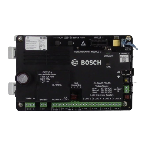
Page 71: Control Panel Board Overview
10 ᅳ Heartbeat LED (blue) Installer keypads and SERVICE MODE, page 94 11 ᅳ RESET button 12 ᅳ Terminals for Output B and Output C Open collector outputs, page 50 Bosch Security Systems, Inc. Installation Manual 2018.07 | 16 | F.01U.287.180... - Page 72 18 ᅳ Terminals for OUTPUT A OUTPUT A jumper, page 19 19 ᅳ Battery terminals Secondary (DC) power, page 21 20 ᅳ 18 VAC power input terminals Primary (AC) power, page 21 2018.07 | 16 | F.01U.287.180 Installation Manual Bosch Security Systems, Inc.
-
Page 73: System Wiring Diagrams
Device Circuits) 120 VAC primary, 18 VAC 22 VA secondary) 3 ᅳ To earth ground 10 ᅳ To ICP-EZTS Tamper Switch 4 ᅳ D122/D122L, as required 11 ᅳ Programmable outputs Bosch Security Systems, Inc. Installation Manual 2018.07 | 16 | F.01U.287.180... -
Page 74: Battery Lead Supervision Wiring
OUTPUT A PWR A B COM Callout ᅳ Description 1 ᅳ D113 Supervision module, battery lead, if required 2 ᅳ Batteries 3 ᅳ To supervision point 4 ᅳ Control panel 2018.07 | 16 | F.01U.287.180 Installation Manual Bosch Security Systems, Inc. -
Page 75: 2-Wire Smoke Wiring (B201)
2 ᅳ Interconnect wiring cable 3 ᅳ B201 4 ᅳ EOL resistor 5 ᅳ 1.8 kΩ EOL resistor (P/N: F01U009011) (included with the module) 6 ᅳ Smoke reset wire Bosch Security Systems, Inc. Installation Manual 2018.07 | 16 | F.01U.287.180... -
Page 76: 2-Wire Smoke Wiring (D125B)
The control panel does not have an on-board NAC. For systems requiring a NAC, use a D192G. Notice! UL requirement For UL Listed fire alarm applications, install a D192G. For detailed instructions, refer to the corresponding document listed in Related documentation, page 12. 2018.07 | 16 | F.01U.287.180 Installation Manual Bosch Security Systems, Inc. - Page 77 1 ᅳ Control panel 2 ᅳ Output jumper set to configure OUTPUT A terminal C for AUX POWER (jumper cover removed) 3 ᅳ D192G 4 ᅳ 1k Ω EOL resistor (P/N: F01U033966) Bosch Security Systems, Inc. Installation Manual 2018.07 | 16 | F.01U.287.180...
-
Page 78: Sdi2 Devices General System Wiring
SDI2 modules use the SDI2 bus to communicate with one another. You can wire modules via home run, daisy chain, or single level T-tap anywhere on the SDI2 bus. 2018.07 | 16 | F.01U.287.180 Installation Manual Bosch Security Systems, Inc. - Page 79 There can only be a difference of 2 volts (maximum) between the AUX power terminals of the control panel or power supply and the device for the modules and keypads to work properly under all conditions. Bosch Security Systems, Inc. Installation Manual 2018.07 | 16 | F.01U.287.180...
- Page 80 Table 18.9: Maximum cable length Notice! Use unshielded cable only. Maximum capacitance of 140nF (140,000 pF) per system. Contact the wire manufacturer for the capacitance ratings of the wire being used. 2018.07 | 16 | F.01U.287.180 Installation Manual Bosch Security Systems, Inc.
-
Page 81: Wiring Label
Avertissement : guide de l'utilisateur (réf. : F01U287181) : seul l'occupant est autorisé à le retirer. Minimum system requirements for Classification in accordance with ANSI/SIA CP-01-2010 Bosch Security Systems, Inc. recommends testing the entire system UL Listed and Classified control unit Model B5512, B4512 or B3512;... -
Page 82: Approved Applications
Control Panels Approved applications The UL System Chart references the components that are evaluated and listed by UL for compatibility with B6512/B5512/B4512/B3512. These components meet the basic system requirements for the applicable standard. Refer to Compatible UL listed components, page 87. - Page 83 15 ᅳ End-of-line (EOL) resistor 8 ᅳ Alarm input point 16 ᅳ Safe Use Terminals 1 through 8. (Select only one.) Use a D113 Battery Lead Supervision Module to supervise the battery connections Bosch Security Systems, Inc. Installation Manual 2018.07 | 16 | F.01U.287.180...
- Page 84 14 ᅳ Terminal TB1 Use Terminals 1 through 8. (Select only one.) Notice! Bell Test at Arming UL Standard 365 requires a Bell Test at arming for bank safe and vault applications. 2018.07 | 16 | F.01U.287.180 Installation Manual Bosch Security Systems, Inc.
-
Page 85: Fire Applications
The control panel does not support multiple detectors in alarm. The control panel is compatible with detectors with optional features. Do not mix detectors from different manufacturers on the same circuit. Bosch Security Systems, Inc. Installation Manual 2018.07 | 16 | F.01U.287.180... -
Page 86: Enclosures
Notice! Test weekly Perform a fire test once each week. 19.1.4 Enclosures Mount the control panel assembly in any of the Bosch Security Systems, Inc. enclosures listed: – B10 Medium Control Panel Enclosure – B11 Small Control Panel Enclosure –... -
Page 87: Combination Fire And Intrusion Alarm Systems
Opt. Opt. Opt. Opt. Communication Module B430 Plug-in Telephone Opt. Opt. Opt. Opt. Opt. Opt. Opt. Communicator B440 Conettix Plug-in Opt. Opt. Opt. Opt. Opt. Opt. Opt. Cellular Communicator Bosch Security Systems, Inc. Installation Manual 2018.07 | 16 | F.01U.287.180... - Page 88 Opt. Opt. Opt. Opt. D192G Class “B”, Style Y Opt. Req. Opt. Opt. Opt. Opt. Opt. Bell Circuit Supervision D8004 Transformer Opt. Opt. Opt. Opt. Opt. Opt. Opt. Enclosure 2018.07 | 16 | F.01U.287.180 Installation Manual Bosch Security Systems, Inc.
-
Page 89: Standby Battery Requirements And Calculations
=______ B444 ______ =______ =______ B450 ______ xQty =______ xQty =______ xQty =______ B520 ______ xQty =______ xQty =______ xQty =______ B810 ______ xQty =______ xQty =______ xQty =______ Bosch Security Systems, Inc. Installation Manual 2018.07 | 16 | F.01U.287.180... - Page 90 Total Ah requirements must not exceed the Ah capacity of batteries: – One D126 Battery=7 Ah – Two D126 Batteries=14 Ah – One D1218 Battery=18 Ah Table 19.11: General ampere-hour (Ah) calculation formula 2018.07 | 16 | F.01U.287.180 Installation Manual Bosch Security Systems, Inc.
-
Page 91: Household Fire Warning Equipment
One D126 Battery = 7 Ah – Two D126 Batteries = 14 Ah – One D1218 Battery = 17.2 or 18 Ah Table 19.14: Household fire ampere-hour (Ah) calculation formula Bosch Security Systems, Inc. Installation Manual 2018.07 | 16 | F.01U.287.180... -
Page 92: Ul 365 - Police Station Connected Burglar Alarm Units And Systems
Applicable for both IP and cellular communication. Requirement Parameter Supervision interval for IP and Cellular Panel Wide Parameters > Enhanced Communications > Receiver communication is 200 seconds (UL) Supervision Time set to 200 seconds 2018.07 | 16 | F.01U.287.180 Installation Manual Bosch Security Systems, Inc. -
Page 93: Ulc
Supervision Time set to Custom, Poll Rate set to 89, ACK Wait Time set to 15, and Retry Count set to 5 19.8 Conduct testing monthly, with the primary de-energized. Bosch Security Systems, Inc. Installation Manual 2018.07 | 16 | F.01U.287.180... -
Page 94: Keypad Installer Menu
Press and hold the control panel RESET button until the Heartbeat LED flashes fast. The keypad shows SERVICE MODE and prompts for the installer passcode. Enter your installer passcode and press Enter. 2018.07 | 16 | F.01U.287.180 Installation Manual Bosch Security Systems, Inc. - Page 95 Press [2] Enhanced Comm Parms. – Go to [1] Programming Menu > [1] Reporting > [2] Network > [2] Enhanced Comm Parms. Bosch Security Systems, Inc. Installation Manual 2018.07 | 16 | F.01U.287.180...
- Page 96 Cloud Plug-in Module Srvc Byp menu Versions menu Cloud menu Exit User menu trees Menu tree The following graphics show the menu tree for the B94x / B93x keypads. 2018.07 | 16 | F.01U.287.180 Installation Manual Bosch Security Systems, Inc.
- Page 97 Turn Off Select Area Call Via Phone Go to Area Extend Close Bypass Firmware Points Bypass Unbypass Points Cycle Door Srv Bypass Unlock Door Access Lock Door Secure Door Bosch Security Systems, Inc. Installation Manual 2018.07 | 16 | F.01U.287.180...
- Page 98 View Log Set Date/ Time Format Schedule Brightness Volume Keypad Keypress Dflt Text Nightlight Presence Menu tree The following graphics show the menu tree for the B92x / B91x keypads. 2018.07 | 16 | F.01U.287.180 Installation Manual Bosch Security Systems, Inc.
- Page 99 6: Update Firmware 1: Bypass Points 5: Bypass 1: Cycle Door 7: View Serv 2: Unbypass Bypassed Points 2: Unlock Door 8: Access 3: Lock Door 4: Secure Door Bosch Security Systems, Inc. Installation Manual 2018.07 | 16 | F.01U.287.180...
- Page 100 – Save. B91x/B92x keypads typically use Enter to save. The B93x/B94x keypads typically use Save to save. The B94x keypad uses the key to save from the Qwerty keyboard. 2018.07 | 16 | F.01U.287.180 Installation Manual Bosch Security Systems, Inc.
-
Page 101: Program Menu (Programming)
Go to [1] Programming Menu > [1] Reporting > [1] Phone. The keypad shows the phone number and phone format for the phone destination. /Previous or /Next to go to the destination you want to edit. Depending on keypad model: Bosch Security Systems, Inc. Installation Manual 2018.07 | 16 | F.01U.287.180... -
Page 102: Reporting > [2] Network Menu Parameters
Depending on keypad model: Press Enter and then press Disable or Enable. -or- Press Enter. Press Save or Enter. The keypad shows Parameter saved. Escape from the menu. Network Address Port Number 2018.07 | 16 | F.01U.287.180 Installation Manual Bosch Security Systems, Inc. -
Page 103: Reporting > [3] Routing Menu Parameters
Use routing to program primary and backup destinations over standard telephone lines, local area network (LAN) or wide area network (WAN). In this menu, you can designate the primary and backup destinations for up to four routes. Bosch Security Systems, Inc. Installation Manual 2018.07 | 16 | F.01U.287.180... -
Page 104: Reporting > [4] Personal Note Menu Parameters
In this menu, you can add a phone number or email address to each personal notification identifier (1 through 16). Notification Phone number or email address Number 2018.07 | 16 | F.01U.287.180 Installation Manual Bosch Security Systems, Inc. -
Page 105: Network > [1] Ethernet > (Choose The Bus Module Or On-Board) > [1] Module
Module settings DHCP/AutoIP Enable Yes/No UPnP Enable Yes/No IPv4 Address 0.0.0.0 _______________________________ IPv4 Subnet Mask 255.255.255.255 _______________________________ Default Gateway 0.0.0.0 _______________________________ HTTP Port Number _______________________________ IPv4 Server Address 0.0.0.0 _______________________________ Bosch Security Systems, Inc. Installation Manual 2018.07 | 16 | F.01U.287.180... -
Page 106: Network > [1] Ethernet > (Choose The Bus Module Or On-Board) > [2] Address
Go to [1] Programming Menu > [2] Network > [1] Ethernet > (choose the bus module or on-board) > [1] Module Parameters > [2] Subnet Mask. Press Edit or Enter to edit the subnet mask address. 2018.07 | 16 | F.01U.287.180 Installation Manual Bosch Security Systems, Inc. -
Page 107: Network > [1] Ethernet > (Choose The Bus Module Or On-Board) > [3] Dns
Delete the existing number, if necessary, and then enter the new number. Use Previous or /Next to move to a different byte. Press Save or Enter. The keypad shows Parameter saved. Escape from the menu. Bosch Security Systems, Inc. Installation Manual 2018.07 | 16 | F.01U.287.180... -
Page 108: Network > [2] Cellular > (Choose The Sdi2 Cellular Module Or Plug-In Module)
Go to [1] Programming Menu > [2] Network > [2] Cellular > (choose the SDI2 cellular module or plug-in module) > [3] Access Pt Password. The keypad shows the current configuration. Press Edit or Enter to edit the configuration. 2018.07 | 16 | F.01U.287.180 Installation Manual Bosch Security Systems, Inc. -
Page 109: Rps > [1] Rps Passcode Menu Parameters
Go to [1] Programming Menu > [3] RPS > [3] RPS IP Address. Depending on keypad model: Press Edit as IPv4 for an IP address, or Edit as Name for a hostname. -or- Bosch Security Systems, Inc. Installation Manual 2018.07 | 16 | F.01U.287.180... -
Page 110: Rps > [4] Rps Port Number Menu Parameters
Press Enter to edit the area and Enter to edit the Area On state for the selected area. Use Previous or Next to toggle between the Yes and No options. Press Save or Enter. The keypad shows Parameter saved. Escape from the menu. 2018.07 | 16 | F.01U.287.180 Installation Manual Bosch Security Systems, Inc. -
Page 111: Keypad Menu Parameters
No keypad / B91x / B92x / B93x / B94x No Device / Area Wide / Acct Wide / Panel Wide Keypad 6 No keypad / B91x / B92x / B93x / B94x No Device / Area Wide / Acct Wide / Panel Wide Bosch Security Systems, Inc. Installation Manual 2018.07 | 16 | F.01U.287.180... -
Page 112: Users Menu Parameters
/Next to toggle between user 000 (service user) and user 001 and go to the user you want to edit. Press Edit or Enter to edit the selected user. The curser flashes at the editing location. 2018.07 | 16 | F.01U.287.180 Installation Manual Bosch Security Systems, Inc. -
Page 113: Points Menu Parameters
Use the parameters in this menu to assign a Point Source and a Point Profile to each point. The Point Source parameter assigns the point to a device (on-board, Octo-input, and wireless are examples). The Point Profile determines how the point operates. Bosch Security Systems, Inc. Installation Manual 2018.07 | 16 | F.01U.287.180... - Page 114 _(30)_ _(30)_ _(30)_ _(30)_ Entry Tone Off Silent Bell Ring Until Restored Audible After Two Fails Invisible Point Buzz on Fault __(0)__ __(0)__ __(0)__ __(0)__ __(0)__ __(0)__ __(0)__ __(0)__ 2018.07 | 16 | F.01U.287.180 Installation Manual Bosch Security Systems, Inc.
- Page 115 Interior: Delay Point Profile 12 Interior: Instant, Local Disarmed Point Profile 13 Interior: Follower Point Profile 14 Maintained Keyswitch Point Profile 15 Momentary Keyswitch Point Profile 16 Point Opening/Closing Bosch Security Systems, Inc. Installation Manual 2018.07 | 16 | F.01U.287.180...
- Page 116 Cross Point Alarm Verify Resettable Alarm Abort Wireless Point Supervision ____ ____ ____ ____ ____ ____ _____ _____ Time** (None) Custom Function Disabled Disabled Disabled Disabled Disabled Disabled Disabled Disabled 2018.07 | 16 | F.01U.287.180 Installation Manual Bosch Security Systems, Inc.
- Page 117 __(0)__ __(0)__ Watch Point Output Response Type __(0)__ __(0)__ __(0)__ __(0)__ Display as Device Local While Disarmed Local While Armed Disable Restorals FA Returnable Bypass Returnable Bypassable Swinger Bypass Bosch Security Systems, Inc. Installation Manual 2018.07 | 16 | F.01U.287.180...
- Page 118 ____ _____ ____ _____ ____ _____ ____ _____ ____ _____ ____ _____ ____ _____ ____ _____ ____ _____ ____ _____ ____ _____ ____ _____ ____ _____ ____ _____ ____ 2018.07 | 16 | F.01U.287.180 Installation Manual Bosch Security Systems, Inc.
- Page 119 16. Press Edit or Enter to edit the name for the selected point. 17. Delete the existing characters, if necessary, and enter the new characters. 18. Press Save or Enter. The keypad shows Parameter saved. Bosch Security Systems, Inc. Installation Manual 2018.07 | 16 | F.01U.287.180...
-
Page 120: Disable Programming Menu
Enter the installer passcode, and then open the [1] Installer Menu. Go to [2] Wireless > [1] RF Point Menu > [2] Replace Point RFID. The keypad lists any enrolled points. 2018.07 | 16 | F.01U.287.180 Installation Manual Bosch Security Systems, Inc. -
Page 121: Rf Point Menu> [3] Remove Point Rfid
Press Enter to replace the device. The keypad instructs you to reset the new device. Initiate discovery on a RADION device per the device instructions, or press the RESET button on an Inovonics device. Bosch Security Systems, Inc. Installation Manual 2018.07 | 16 | F.01U.287.180... -
Page 122: Rf Repeater Menu > [3] Remove Repeater
Press Enter to view the state. The menu scrolls through the following sub-categories, with the results of the diagnostic check: State, Missing, Tamper, Low-Battery. When finished viewing the information, escape from the menu. 2018.07 | 16 | F.01U.287.180 Installation Manual Bosch Security Systems, Inc. -
Page 123: Diags Menu
– Link (Yes or No. Yes indicates a data connection to the carrier. No indicates a connection problem.) – IPv4 IP (The IP address of the cellular radio on the carrier’s network.) – Base ID Bosch Security Systems, Inc. Installation Manual 2018.07 | 16 | F.01U.287.180... -
Page 124: Ip Camera
[4] Service Bypass (Serv Byp) menu In this menu, you can edit the Service Bypass points. Service Bypass Enter the installer passcode, and then open the [1] Installer Menu. 2018.07 | 16 | F.01U.287.180 Installation Manual Bosch Security Systems, Inc. -
Page 125: Versions Menu
Press the icon or softkey for the item for which you want view the version. -or- /Previous or /Next to scroll through the list of items for which you can view the version. Press Enter to view the version. Escape from the menu. Bosch Security Systems, Inc. Installation Manual 2018.07 | 16 | F.01U.287.180... -
Page 126: Cloud Menu
Press Edit or Enter (or escape from the menu to exit without making a change). /Next to go to the desired option. Press Save or Enter. The keypad shows Parameter saved and closes the menu. 2018.07 | 16 | F.01U.287.180 Installation Manual Bosch Security Systems, Inc. -
Page 127: Specifications
13.4 V - Battery Restoral Report sent. Battery float charged. Environmental Temperature 0℃ to +49℃ (+32℉ to 122℉) Relative Humidity 5% to 93% at +32℃ (+90℉) non-condensing Arming stations B942/B942W, B930, B921C, B920, B915/B915I, Keyswitch Bosch Security Systems, Inc. Installation Manual 2018.07 | 16 | F.01U.287.180... - Page 128 Short circuit current - 5 mA Compatible B10 Medium Control Panel Enclosure, B11 Small Control Panel Enclosure, D2203 enclosures Enclosure, D8103 Universal Enclosure, D8108A Attack Resistant Enclosure, D8109 Fire Enclosure 2018.07 | 16 | F.01U.287.180 Installation Manual Bosch Security Systems, Inc.
-
Page 129: Wire Requirements
18 AWG to 12 AWG (1.02 mm to 2 mm) Earth ground 16 AWG to 14 AWG (1.5 mm to 1.8 mm) BAT + Battery + Bosch supplied wire lead, included with control panel.. BAT - Battery - OUTPUT A NO Output A normally open 22 AWG to 12 AWG (0.65 mm to 2 mm) -
Page 130: Appendix
The B5512 supports up to 4 modules. The B4512 supports up to 2 modules. The B3512 does not support the B208 module. B208 address number B6512 point numbers B5512 point numbers B4512 point numbers 11 - 18 11 - 18... -
Page 131: B901 Address Settings
B308 address number B6512 output B5512 output B4512 output numbers numbers numbers 81 - 88 22.1.3 B901 address settings The B6512 supports four B901 Access Control Modules. Address Designation Disabled 0,1 to 0,4 Doors 1 through 4 22.1.4 B91x address settings Address Switches Bosch Security Systems, Inc. -
Page 132: Reporting And Device Number Information
Installer Services Portal Access programming tool (available in Europe, Middle East, Africa, and China) access occurred AC Fail - mains power supply Pssss AC Loss 1 301 00 000 2018.07 | 16 | F.01U.287.180 Installation Manual Bosch Security Systems, Inc. - Page 133 1 300 00 000 Trouble Battery Charger Circuit Rsss9 System Trouble Restore 3 300 00 000 Trouble Restoral Bypass by Sked Nspppp Nriaa/ Zone/Sensor Bypass 1 570 aa ppp aikkkUBpppp Bosch Security Systems, Inc. Installation Manual 2018.07 | 16 | F.01U.287.180...
- Page 134 Restore Communication trouble by TsB01 NphhhYS Communication Trouble 1 350 00 000 phone Communication trouble by NsB01 NphhhYK Communication Trouble 3 350 00 000 phone restored Restore 2018.07 | 16 | F.01U.287.180 Installation Manual Bosch Security Systems, Inc.
- Page 135 Fail to Open by Area TsssE NriaOl Failed to Open 1 453 aa 000 Fire Alarm Fspppp NriaaFApppp Fire 1 110 aa ppp Fire Cancel \iiii Nriaa/idiiiiFC Cancel 1 406 aa uuu Bosch Security Systems, Inc. Installation Manual 2018.07 | 16 | F.01U.287.180...
- Page 136 Invalid Point Transmitter Rpppp NriaaBRpppp Loss of Supervision -RPM 3 382 aa ppp Restore Restore Invalid Popit Address Vpppp NriaaUYpppp Loss of Supervision - RPM 1 382 aa ppp 2018.07 | 16 | F.01U.287.180 Installation Manual Bosch Security Systems, Inc.
- Page 137 Nriaa/idiiiiOJ Late O/C 1 452 aa uuu Parameters changed NsD02 Panel Programming 1 306 00 000 Changed Personal Notification TsB01 NpiddddYS Communication Trouble 1 350 0 zzz Communication Trouble Bosch Security Systems, Inc. Installation Manual 2018.07 | 16 | F.01U.287.180...
- Page 138 Maintenance Alert Restore 3 393 aa ppp Replace User’s Key Fob NsD30 NidiiiiDAuuuu Local Only Local Only (Assign Card Event) Restoral Rpppp NriaaBRpppp Sensor Trouble Restore 3 380 aa ppp 2018.07 | 16 | F.01U.287.180 Installation Manual Bosch Security Systems, Inc.
- Page 139 PS Over Current Restore 3 312 00 Restore SDI Device Tamper TsssD Exp. Module Tamper 1 341 00 SDI Device Tamper Restore TsssD Exp. Module Tamper 3 341 00 Restore Bosch Security Systems, Inc. Installation Manual 2018.07 | 16 | F.01U.287.180...
- Page 140 Status: Gas Alarm SApppp NriaaGAppp Status: Gas Supervisory SJpppp NriaaGSppp Status: Gas Trouble STpppp NriaaGTppp Status: Open by Area SOssss OriaOP Swinger Bypass Nsppp NriaaUBpppp Swinger Bypass 1 575 aa ppp 2018.07 | 16 | F.01U.287.180 Installation Manual Bosch Security Systems, Inc.
-
Page 141: Sdi2 Address Information
All point numbers, user ID’s, output numbers, and device identifier numbers are formatted as 4-digit numbers (right justified with zeros) when transmitted from the control panel in Modem4 format. SDI2 address zzz data values Description 01-08 001-008 SDI2 Keypad 1 through 8 Bosch Security Systems, Inc. Installation Manual 2018.07 | 16 | F.01U.287.180... -
Page 142: Device Numbers (Zzz, Dddd)
418, 428, 438, 448 Destinations 1 through 4 via On-board Cell# [1-2] Cellular Module On-Board PN Dest [1 – 16 ] 451 – 466 Personal notification destinations number 1 through 16 2018.07 | 16 | F.01U.287.180 Installation Manual Bosch Security Systems, Inc. -
Page 143: Special User Ids (Uuuu, Iiii)
The point numbers for manually created keypad alarm events are changed in control panel firmware version 3.01. Originating keypad Control panel firmware Control panel firmware version 2.04 and lower, version 3.01 and higher, reported point number reported point number Keypad 1 Bosch Security Systems, Inc. Installation Manual 2018.07 | 16 | F.01U.287.180... -
Page 144: Autoip
Apply a new registry key to the computer to enable AutoIP. Make sure that you have permission from your company IT department before changing the registry. Adding a new registry key, if required Open Notepad. 2018.07 | 16 | F.01U.287.180 Installation Manual Bosch Security Systems, Inc. - Page 145 Use Windows Explorer to find the saved file. Double-click the file to add it to the computer registry. Restart the RPS or Installer Services Portal programming tool computer. Text for the AutoIP.reg file: Windows Registry Editor Version 5.00 [HKEY_LOCAL_MACHINE\SYSTEM\CurrentControlSet\Services\Tcpip\Parameters] "IPAutoconfigurationEnabled"=dword:00000001 Bosch Security Systems, Inc. Installation Manual 2018.07 | 16 | F.01U.287.180...
- Page 147 Bosch Security Systems, Inc. Bosch Sicherheitssysteme GmbH 130 Perinton Parkway Robert-Bosch-Ring 5 Fairport, NY 14450 85630 Grasbrunn Germany www.boschsecurity.com © Bosch Security Systems, Inc., 2018...