Table of Contents
Advertisement
Quick Links
—
ABB Group
Electrification Products Division
Business Unit Building Products
www.abb.com/lowvoltage
© Copyright 2018 ABB. All rights reserved.
Due to possible changes in design and materials, the features and
sizes contained in this catalog are to be considered as binding
only after confirmation by ABB.
Advertisement
Table of Contents

Related Manuals for ABB CMS-700


Summary of Contents for ABB CMS-700
- Page 1 Electrification Products Division Business Unit Building Products www.abb.com/lowvoltage © Copyright 2018 ABB. All rights reserved. Due to possible changes in design and materials, the features and sizes contained in this catalog are to be considered as binding only after confirmation by ABB.
- Page 2 — CIRCUIT MONITORING SYSTEM CMS-700 User manual • Energy transparency at branch level for optimal load distribution • Measurements of all kinds of currents (DC,AC, or mixed) up to 160A • Simplified installation thanks to quick mounting of sensors • Smart commissioning in only a few minutes...
- Page 4 CMS-700 SYSTEM CIRCUIT MONITORING SYSTEM (CMS) — Table of contents Use and storage of the manual General information Packaging contents 008–011 Product overview 012–013 Measurements and Events definition Memory architecture 015–018 Components of CMS system 019–022 Installation Guide 023–024 Wiring diagrams 025–028...
- Page 5 CMS-700 SYSTEM CIRCUIT MONITORING SYSTEM (CMS)
- Page 6 The information contained in this document is subject to change without notice and cannot be considered as an obligation by ABB Ltd. ABB Ltd. is not liable for any errors that may appear in this document. ABB Ltd. is not liable under any circumstances for any direct, indirect, special, incidental or consequential damage of any kind that may arise from using this document.
-
Page 7: General Information
Use a dry cloth. Installation to mains Installation of CMS-700 to mains shall include a switch or circuit breaker for the connection to mains. The switch or circuit breaker must be suitably located and easily reachable and must be marked as the disconnecting device for the CMS-700. - Page 8 CMS-700 SYSTEM CIRCUIT MONITORING SYSTEM (CMS) — Packaging contents - Control unit (CMS-700) - Installation manual CMS-700 control unit Energy Monitor 96 Attention: The following items are not included in the delivery of the product 1) CMS-Sensors 2) Current transformer (CT)
-
Page 9: Product Overview
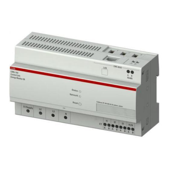
Product overview Intended use The CMS-700 control unit is a measuring instrument for recording the performance and energy of mains and of up to 96 branch sensors. The system consists of a control unit and sensors with different measurement ranges. - Page 10 CMS-700 SYSTEM CIRCUIT MONITORING SYSTEM (CMS) — Product overview — Reset button There is a recessed button to restart the device or for resetting it to a defined as-delivered condition. • Pressing the button for 3 to less than 6 seconds restarts the device with current settings •...
-
Page 11: Technical Specifications
CMS-700 SYSTEM CIRCUIT MONITORING SYSTEM (CMS) — Product overview Technical specifications CMS-700 Control Unit IEC61010-1 Supply voltage [VAC] 90-240 (L1-N) Voltage measurement range [VAC] 90-240 (L1-N, L2-N, L3-N) UL 508 / CSA C22.2 No. 14 Supply voltage [VAC] 80-277 (L1-N) —... - Page 12 CMS-700 SYSTEM CIRCUIT MONITORING SYSTEM (CMS) — Product overview Overall dimensions 43.6 58.1...
- Page 13 — Principle of measurement The principle of measurement for AC of the CMS-700 control unit includes measurement on the mains and branches. On the mains side, all values are measured directly. On the branches, current is measured while voltage, power factor as well as active power and energy are calculated using measured mains values.
- Page 14 — Measurements and Events definition — Events If a measurement object (e.g. TRMS current of a branch) crosses predefined threshold conditions (value, direction and delay time) then an event is registered. Following options linked to events logging are available: • Visualization of all detected events in WebUi •...
- Page 15 CMS-700 SYSTEM CIRCUIT MONITORING SYSTEM (CMS) — Memory architecture The measured values of the main power network and those of the 96 outputs are stored in the following memory areas: Stored values Mains Branches • Voltage [V]: L1, L2, L3 •...
- Page 16 CMS-700 SYSTEM CIRCUIT MONITORING SYSTEM (CMS) — Components of CMS system — Control Unit RJ45-socket for LAN connection CMS-Bus up to 96 sensors Terminal RS-485 Modbus (RTU) LEDs Reset button Terminals L1, L2, L3, N • Wire gauge max 2.5 mm •...
- Page 17 CMS-700 SYSTEM CIRCUIT MONITORING SYSTEM (CMS) — Components of CMS system — Sensors overview System Pro M, SMISSLINE S800 DIN rail Cable tie Mounting method for all MCBs, RCDs, for MCBs for fuse for all S800 devices universally universally RCBOs with...
- Page 18 CMS-700 SYSTEM CIRCUIT MONITORING SYSTEM (CMS) — Components of CMS system — Current Transformer Example: CT PRO XT 250 — CMS Flat Cable The CMS flat cable is a 4-pin cable for connecting multiple sensors to one control unit. The cable is available in the following four lengths: 2m (CMS-800), 5m (CMS-802), 10m (CMS-803), and 30m (CMS-805).
- Page 19 CMS-700 SYSTEM CIRCUIT MONITORING SYSTEM (CMS) — Components of CMS system — Connector Set The CMS-820 connector set contains connector housings and connectors to connect the flat cable to the sensors. 35 x connector housing 35 x connector...
- Page 20 To assemble of the control unit, perform steps 1 and 2. The device can be mounted horizontally or vertically. To disconnect, perform steps 3 and 4. • The CMS-700 can be mounted on all 35mm DIN rails (DIN50022) • The device can be installed for single or three phase use...
- Page 21 CMS-700 SYSTEM CIRCUIT MONITORING SYSTEM (CMS) — Installation Guide — Flat Cable – Assembly of Connectors • Use the connectors only once • Connect max. 96 sensors to each CMS-Bus interface of the control unit • Consider the maximum flat cable length •...
- Page 22 — Mounting of System pro M compact and SMISSLINE Sensors • Sensors fit to all ABB installation devices with twin terminals • Flat cable should not exert force on the sensor, otherwise measuring errors may occur 1. Unscrew the terminal of the installation device.
- Page 23 CMS-700 SYSTEM CIRCUIT MONITORING SYSTEM (CMS) — Installation Guide — Mounting of cable tie sensors • The cable should not exert force on the sensor, otherwise measuring errors may occur 1. Insert the cable into the installed device through the opening on the sensor.
-
Page 24: Wiring Diagrams
The contacts l1, l2, l3, l4/ N are provided for connecting the external current transformer. Installation to mains Installation of CMS-700 to mains shall include a switch or a circuit breaker for the connection to them. The switch or circuit breaker must be suitably located and easily reachable and must be marked as the disconnecting device for the CMS-700. - Page 25 CMS-700 SYSTEM CIRCUIT MONITORING SYSTEM (CMS) — Wiring diagrams Three phase plus neutral Attention: Please, referring to the diagram in the figure aside, notice that N on the supply has to be connected in order to avoid damage of the device...
- Page 26 For further information about manual time setting, settings menu - Other / Time. — Network Connection The following sections show the steps needed to set up the CMS-700 control unit. The control unit can be used in different operating modes: • LAN connection via router •...
- Page 27 CMS-700 SYSTEM CIRCUIT MONITORING SYSTEM (CMS) — Initial Commissioning — LAN connection via Router The CMS-700 control unit is connected to the router using an RJ45 cable (network). RJ45 socket for LAN connection Accessing the Web UI via hostname Host name: CMS-700 Port: 8000 To be added to the IP address to define the port number (e.g.
- Page 28 — Initial Commissioning The control unit is set up using a web interface. To connect a PC or laptop to the CMS-700 without DHCP, you need to configure the LAN interface with a static IP address. Using the example of Windows, the following shows the configuration steps.
- Page 29 Enter IP Address: 192.168.1.200:1.5 and Subnet Mask: 255.255.255.0 and confirm with OK Make sure that the IP address on the LAN is not already taken. In case it is taken, adjustments are necessary. (192.168.1.x; x = 2…199, 201…255) Now connect your device to the CMS-700 control unit...
- Page 30 CMS-700 SYSTEM CIRCUIT MONITORING SYSTEM (CMS) — Web User Interface Overview The web user interface is designed for use on browser-based devices. The recommended web browser is Google Chrome, other supported web browsers are Safari, Firefox, Opera, Internet Explorer. —...
- Page 31 CMS-700 SYSTEM CIRCUIT MONITORING SYSTEM (CMS) — Web User Interface Overview — Web Server overview Home Menu Setting Menu Help Function View Settings Select for example online - or historical values Submenu Logout Button Expert Button Not available in all views Two menus are available •...
- Page 32 CMS-700 SYSTEM CIRCUIT MONITORING SYSTEM (CMS) — WEB UI - Settings Menu Safe shutdown: To make sure all settings are saved, it is recommended to carry out a safe shutdown after changing any settings and then restart the system (Settings menu - Other / System reset).
- Page 33 CMS-700 SYSTEM CIRCUIT MONITORING SYSTEM (CMS) — WEB UI - Settings Menu — Settings Menu - Branches The menu allows to have access to the information briefly listed below together with the buttons you can use. It is possible to use Selection Filter and Sort Function on Phase and Group labels to find desired values.
- Page 34 CMS-700 SYSTEM CIRCUIT MONITORING SYSTEM (CMS) — WEB UI - Settings Menu — Settings Menu - Events This page allows to set events. If an event occurs, it is shown in the historical events menu. An event can occur after exceeding the selected threshold values (cross-up) or after measuring values lower than the selected threshold values (cross-down) for a determined period (time delay).
- Page 35 CMS-700 SYSTEM CIRCUIT MONITORING SYSTEM (CMS) — WEB UI - Settings Menu — Settings Menu - Data export In order to carry out data export via E-mail and/or FTP, contact data for e-mail and FTP server need to be configured (see Settings menu - Email, FTP). The following information has to be provided...
- Page 36 CMS-700 SYSTEM CIRCUIT MONITORING SYSTEM (CMS) — WEB UI - Settings Menu — Settings Menu - E-mail / FTP Settings for contact details. E-mail and FTP settings are needed in order to carry out e-mail and FTP data export. Please make sure that no firewall will block the export.
- Page 37 The following information have to be set to correctly have access to the user interface via IP: IP Mode DHCP or static (Note: With DHCP you can find and define an IP address via the router by MAC address or device name - CMS-700) The fallback IP address is: 192.168.1.200:8000 IP Address...
- Page 38 CMS-700 SYSTEM CIRCUIT MONITORING SYSTEM (CMS) — WEB UI - Settings Menu — Settings Menu - Communication / SNMP The SNMP service is disabled on the device by default. In order to activate it, it is necessary to open the following panel:...
- Page 39 CMS-700 SYSTEM CIRCUIT MONITORING SYSTEM (CMS) — WEB UI - Settings Menu — Settings Menu - Communication / SNMP Version 3: To enable version 3 mark the v.3 checkbox, enter port number, password, user name, and engine ID. The same as for versions v.1/2c port number must be 161 or greater than 1024. The password for version 3 must have at least 8 signs, while the engine ID must have at least 12 characters in hexadecimal format.
- Page 40 CMS-700 SYSTEM CIRCUIT MONITORING SYSTEM (CMS) — WEB UI - Settings Menu — Settings Menu – Communication / Modbus This section allows to have access to both Modbus TCP and RTU settings. Modbus TCP It is possible to enable or disable the corresponding communication protocol and to change the TCP port.
- Page 41 CMS-700 SYSTEM CIRCUIT MONITORING SYSTEM (CMS) — WEB UI - Settings Menu — Settings Menu – SSL Certificate In this section it is possible to upload or generate a .pem file containing a private key and a public certificate in order to provide a secure connection via the web browser.
- Page 42 CMS-700 SYSTEM CIRCUIT MONITORING SYSTEM (CMS) — WEB UI - Settings Menu — Settings Menu – SSL Certificate Generate In order to generate a SSL certificate, following configurations must be considered: IP address Indicates your currently configured IP address on the device...
- Page 43 CMS-700 SYSTEM CIRCUIT MONITORING SYSTEM (CMS) — WEB UI - Settings Menu — Settings Menu - Language Currently the Web User Interface supports the following languages:: • English • German • Polish • French • Japanese • Russian...
- Page 44 CMS-700 SYSTEM CIRCUIT MONITORING SYSTEM (CMS) — WEB UI - Settings Menu — Settings Menu - Other / Time It is possible to synchronize the time to compare the one referred to the device and the one referred to the web browser. The synchronization is mandatory in order to visualize and store data. The CMS will synchronizes with the computer system time.
- Page 45 Using this menu you can update the firmware of the control unit. It is highly recommended to update the firmware to the latest version for security and functionality reasons. Please check the ABB website for current SW revision and to download the latest version of the firmware.
- Page 46 To do so, push the ‘’Shutdown’’ button. If the Status LED is shining green without flashing, and if the network LED is out, you can turn off the power supply. For starting the device, turn on the power supply. The CMS-700 will automatically start.
- Page 47 CMS-700 SYSTEM CIRCUIT MONITORING SYSTEM (CMS) — WEB UI - Home Menu — General about Home menu It is possible to visualize mains and branches measured values (online or historical values depending on the time frame), energy consumptions of mains, groups and branches and events (online or historical depending on the time frame).
- Page 48 CMS-700 SYSTEM CIRCUIT MONITORING SYSTEM (CMS) — WEB UI - Home Menu Note: If no graph is visible, it is necessary to synchronize the device time with the "Set time manually" button in the Settings – Other / Time menu.
- Page 49 CMS-700 SYSTEM CIRCUIT MONITORING SYSTEM (CMS) — WEB UI - Home Menu — Home Menu - Branch View / Online values, Historical values Here it is possible to visualize both "Online values" and "Historical values" for the Branches. Sensors for branch measurement have to be first assigned and configured (please refer to Settings menu –...
- Page 50 CMS-700 SYSTEM CIRCUIT MONITORING SYSTEM (CMS) — WEB UI - Home Menu — Home Menu – Energy / Mains, Groups, Branches Here it is possible to visualize energy consumptions of Mains, Groups and Branches. For Mains, consumptions are visualized by phases (L1,L2 and L3), while for Groups they are viasualized divided by user-defined groups.
- Page 51 CMS-700 SYSTEM CIRCUIT MONITORING SYSTEM (CMS) — WEB UI - Home Menu — Home Menu – Energy / Mains, Groups, Branches The Energy - Branches Menu displays active energy values for each individual sensor. You can select more sensors to compare energy consumption within a defined period of time. You can set the display by selecting a date range and resolution.
- Page 52 CMS-700 SYSTEM CIRCUIT MONITORING SYSTEM (CMS) — Modbus — Communication protocol Introducing MODBUS protocol The Modbus serial line protocol is a Master-Slaves protocol. This means that only one master and one or more slave nodes (max. 247) can be connected to the same serial bus. A Modbus communication is always initiated by the master and there is only one transaction at the same time.
- Page 53 2400, 4800, 9600, 19200, 38400, 57600, 115200 Bit/s 19200 Bit/s Data format even parity, odd parity, without parity even parity Line termination resistor (120Ω) needs to be added, if necessary, for CMS-700 having serial number later than 700K1820000. Control unit’s MODBUS-ID Modbus RTU CMS Systems You can connect up to 247 control units to one Modbus RTU line.
- Page 54 CMS-700 SYSTEM CIRCUIT MONITORING SYSTEM (CMS) — Modbus Error Codes Modbus protocol defines a common way of error reporting. Every request (read or write) sent in unicast mode is expected to return a value in packet of the same structure. In case of a message delivery error (not a CRC problem but a message execution problem), the generated response contains a function code with MSB (80h) set and a single byte representing the error code, called “exception code”.
- Page 55 CMS-700 SYSTEM CIRCUIT MONITORING SYSTEM (CMS) — Modbus — — Values with special meanings: Calculated branch power and energy values Values with special meanings: Calculated branch power and energy values Special values Meaning FFFF 7FF0h Data pending, acquisition in progress FFFF 7FF1h …...
- Page 56 CMS-700 SYSTEM CIRCUIT MONITORING SYSTEM (CMS) — Modbus Start / stop command is in the following bit format position: 000S 0000 0CCC CCCC • C Sensor ID • S 1 = Starts fast LED blinking 0 = Stops fast LED blinking Data written has to specify a known Sensor ID.
- Page 57 CMS-700 SYSTEM CIRCUIT MONITORING SYSTEM (CMS) — Simple Network Management Protocol – SNMP Reading of values The protocol is applicable for the following items: • Mains parameters • Calculated values • Measured branch current values If you need to record the values of a subsequent measurement, you have to use the SNMP protocol and the external storage system.
- Page 58 The NET-SNMP package can be downloaded from the link: https://sourceforge.net/projects/net-snmp/files/net-snmp/5.7.3/ In the downloaded zip package, MIB files are available in directory: net-snmp-5.7.3.zip\ net-snmp-5.7.3\mibs\ The objects used in CMS-700 are defined in SNMPv2-MIB.txt and NET-SNMP-EXTEND- MIB.txt. The list of available objects is shown in Table 1. — SNMP objects...
- Page 59 CMS-700 SYSTEM CIRCUIT MONITORING SYSTEM (CMS) — Simple Network Management Protocol – SNMP Examples Some examples of usage on the Linux system using snmpget program from NET-SNMP package are presented below. The ‘#’ is the Linux command prompt. SNMPv1 # snmpget -v1 -c password 192.168.1.200:8002 SNMPv2- MIB::sysUpTime.0 SNMPv2-MIB::sysUpTime.0 = Timeticks: (38471) 0:06:24.71...
- Page 60 CMS-700 SYSTEM CIRCUIT MONITORING SYSTEM (CMS) — Modbus and SNMP Mapping Modbus Standard TCP Port: 8001 Standard SNMP Port: 8002 Addr. Addr. Word Description Resolution Unit Format Access SNMP (hex) (dec) (16-bit) (1-bit value) Variable Name Ongoing measurement values: These registers contain the actual measured data.
- Page 61 CMS-700 SYSTEM CIRCUIT MONITORING SYSTEM (CMS) — Modbus and SNMP Mapping Addr. Addr. Word Description Resolution Unit Format Access SNMP (hex) (dec) (16-bit) (1-bit value) Variable Name Measured hold values: These registers contain the hold values captured at a given time during the execution of a “trigger hold measurement” request.
- Page 62 CMS-700 SYSTEM CIRCUIT MONITORING SYSTEM (CMS) — Modbus and SNMP Mapping Addr. Addr. Word Description Resolution Unit Format Access SNMP (hex) (dec) (16-bit) (1-bit value) Variable Name Branches 3200 12'800 Branch name of Sensor 1 letter string RW (03,10) BranchNameSens1...
- Page 63 CMS-700 SYSTEM CIRCUIT MONITORING SYSTEM (CMS) — Modbus and SNMP Mapping Addr. Addr. Word Description Resolution Unit Format Access SNMP (hex) (dec) (16-bit) (1-bit value) Variable Name Mains measurement registers 9002 36'866 PHASE VOLTAGE L1-N 0.01 unsigned R (03) 9004...
- Page 64 CMS-700 SYSTEM CIRCUIT MONITORING SYSTEM (CMS) — Modbus and SNMP Mapping Addr. Addr. Word Description Resolution Unit Format Access SNMP Variable (hex) (dec) (16-bit) (1-bit value) Name Mains measurement registers 90B0 37'040 ACTIVE ENERGY L2 100Wh unsigned R (03) whL2-100...
- Page 65 The RJ45 LAN connection of the device is compatible with Modbus TCP. Master / Slave The CMS-700 does not have a master function. It operates as a slave and can be addressed accordingly in the Web UI configuration. Master / Slave Each CMS-700 needs its own IP address on the network and must be accessed using this IP address.