Philips act 200 Service Manual
Digital audio player
Hide thumbs
Also See for act 200:
- Specifications (2 pages) ,
- Product manual (35 pages) ,
- Manual (28 pages)
Table of Contents
Advertisement
Quick Links
Download this manual
See also:
Manual
Digital Audio Player
TABLE OF CONTENTS
Technical specification ....................................................1 - 1
Features ..........................................................................1 - 1
Accessories .....................................................................1 - 2
Instruction For Use ................................................1 - 2 ..1 - 8
Safety & Warnings...........................................................2 - 1
Handling chip components ..............................................2 - 2
Disassembly diagram ............................................2 - 3...2 - 4
Service Test Program............................................3 - 1...3 - 2
Set block diagram..................................................3 - 3...3 - 4
Pin description of ICs ............................................3 - 5...3 - 6
Start-up procedure.............................................................3-5
©
Copyright 2001 Philips Consumer Electronics B.V. Eindhoven, The Netherlands
All rights reserved. No part of this publication may be reproduced, stored in a retrieval
system or transmitted, in any form or by any means, electronic, mechanical, photocopying,
or otherwise without the prior permission of Philips.
Published by SL 0238 Service Audio
Printed in The Netherlands
Subject to modification
psa[ 64 / psa[ 128 max
ACT200 MAIN BOARD
Circuit diagram ............................................................4 - 1
Layout diagram - component side ...............................4 - 2
Layout diagram - SMD side .........................................4 - 3
ACT210 MAIN BOARD
Circuit diagram ............................................................4 - 4
Layout diagram - component side ...............................4 - 5
Layout diagram - SMD side .........................................4 - 6
USB BOARD
Circuit diagram ............................................................4 - 7
Layout diagram............................................................4 - 8
Exploded view .................................................................5 - 1
Mechanical partslist .........................................................6 - 1
Electrical partslist ..................................................6 - 2...6 - 6
ACT200
ACT210
all versions
© 3140 785 32180
Advertisement
Table of Contents

Related Manuals for Philips act 200


Summary of Contents for Philips act 200
-
Page 1: Table Of Contents
Electrical partslist ..........6 - 2...6 - 6 © Copyright 2001 Philips Consumer Electronics B.V. Eindhoven, The Netherlands All rights reserved. No part of this publication may be reproduced, stored in a retrieval system or transmitted, in any form or by any means, electronic, mechanical, photocopying, or otherwise without the prior permission of Philips. -
Page 2: Technical Specification
1 - 1 TECHNICAL SPECIFICATION Current consumption General Dimensions (WxHxD) : 60 x 68 x 27 mm Weight without battery : 45 g CONDITION TYP. Output power : 2 x 5 mW 0mA typ. Stand-by mode Playing 1kHz 0dB MP3 file, volume 70mA typ. -
Page 3: Accessories
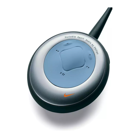
1 - 2 INSTRUCTION FOR UES ACT200----controls front vi ew controls and connections 1 2; 8 bat ter y com par tment switches the set on /off; uses 1 x AAA alkaline or starts / pauses playback Ni-MH battery 2 5 / 6 9 usb in skips to the beginning of a previous / (found in the battery compart-... -
Page 4: Instruction For Use
– software upgradeable and will support future playback formats and sofware exten- – usb port with Windows 98 / Me / 2000 / XP sions that will be made available on www.nike-philips.com. – 64MB(for ACT200), 96MB(for ACT210) ram – will support for future digital rights management technology, including the Secure –... - Page 5 1 - 4 INSTRUCTION FOR USE adjusting volume - / + and eq settings power on / off, playback 2; volume power on and playback, 2; press - / + to decrease / increase the volume. press and hold 2; for 2 seconds to turn on. for ACT210 for ACT200 the volume bar decreases / increases.
- Page 6 1 - 5 INSTRUCTION FOR USE accessories, software: MUSICMATCH Jukebox accessories armband clip magnets wear your digital audio player during sport activity wear your remote control and secure your headphone by securing it to the supplied armband. cord with these wearable magnets. check the polarity of the 2 button magnets.
- Page 7 1 - 6 INSTRUCTION FOR USE software: MUSICMATCH Jukebox and device drivers installing the psa drivers from the next screen, click install MUSICMATCH jukebox and follow the screen installing the psa drivers instructions to install. you must install the device drivers for your computer to recognize the psa player. follow these directions to install the drivers.
- Page 8 .nike-philips.com for more information and firmware upgrades.
- Page 9 – current psa does not download windows – electrostatic discharge. media audio for mac users. remove battery and replace after several seconds. check out www.nike-philips.com for updates. – mp3 file made at compression level exceeding sound skips during playback – electrostatic discharge.
-
Page 10: Safety & Warnings
2 - 1 SAFETY & WARNINGS © ñ WARNING WAARSCHUWING All ICs and many other semiconductors are susceptible to Alle IC´s en vele andere halfgeleiders zijn gevoelig voor electrostatic discharges (ESD). Careless handling during electrostatische ontladingen (ESD). repair can reduce life drastically. Onzorgvuldig behandelen tijdens reparatie kan de levensduur When repairing, make sure that you are connected with the drastisch doen vermindern. -
Page 11: Handling Chip Components
2 - 2 HANDLING CHIP COMPONENTS ESD PROTECTION EQUIPMENT Anti-static table mat large 1200x650x1.25mm 4822 466 10953 small 600x650x1.25mm 4822 466 10958 4822 395 10223 Anti-static wristband Connection box (3press stud connections,1MΩ) 4822 320 11307 Extendible cable (2m,2MΩ ,to connect wristband to connection box) 4822 320 11305 Connecting cable (3m,2MΩ... -
Page 12: Disassembly Diagram
2 - 3 ACT200 DISASSEMBLY DIAGRAM A. To remove Battery Door B. To remove Top Cabinet C. To remove PCB Module D. To remove Battery Holder... - Page 13 2 - 4 2 - 4 ACT200 AND ACT210 DISASSEMBLY DIAGRAM...
- Page 14 3 - 1 3 - 1 ACT200 SERVICE TEST PROGRAM - FLOW CHART To enter the service test program PRELIMINARY 1. Insert the battery SETUP 2. Hold "PLAY" & "NEXT" buttons depressed AMBER LED flashes & 2 beep tone played KEY TEST AUDIO TEST Any key...
-
Page 15: Service Test Program
3 - 2 3 - 2 ACT210 SERVICE TEST PROGRAM - FLOW CHART To enter the service test program PRELIMINARY 1. Insert the battery SETUP 2. Hold "PLAY" & "EQ" buttons depressed Display shows "FW"+ software-version (e.g. FW275.003 ”) “ Enter automatically? (after 2 sec) -
Page 16: Set Block Diagram
3 - 3 3 - 3 ACT200 SET BLOCK DIAGRAM Remote Control Unit Matrix: Play/Pause 1x AAA VDD_CORE VDD_IO Headphone BATTERY Vol+ Vol- XTAL USB D_ USB D+ STMP3410 Connector Head Headphone Phone Jack Vbus_5V Pswitch 4 poles PW_On BATTERY Flash Memory matrix... - Page 17 3 - 4 3 - 4 ACT210 SET BLOCK DIAGRAM Remote Control Unit Matrix: Play/Pause 1x AAA VDD_D VDD_ Headphone BATTERY Vol+ Vol- XTAL USB D_ USB D+ STMP3410 Connector Head Headphone Phone Jack Vbus_5V Pswitch 4 poles PW_On BATTERY Flash Memory Panel...
- Page 18 3 - 5 3 - 5 BLOCK DIAGRAM OF INTEGRATED CIRCUIT Abbreviations and Pin-description of NAND E PROM NAND E PROM - TC58512FT TC58512FT PIN FUNCTIONS The device is a serial access memory which utilizes time-sharing input of address information. The device pin-outs are configured as shown in Figure 1.
- Page 19 3 - 6 3 - 6 BLOCK DIAGRAM OF AUDIO DECODER PIN DESCRIPTION OF AUDIO DECODER STMP3410 STMP3410 100TQFP MODULE TYPE DESCRIPTION 1 02 CF_D4 EMC-CF CompactFlash Data 4 CF_D5 EMC-CF CompactFlash Data 5 FM Radio CF_D6 EMC-CF CompactFlash Data 6 USB Bus Microphone CF_D7...
-
Page 20: Circuit Diagram
4 - 1 4 - 1 CIRCUIT DIAGRAM - ACT200 MAIN BOARD F1 F20 F5 G20 F9 G20 F12 H20 F16 H20 F20 I20 1250 I4 1255 F4 1403 H17 2250 L20 2401 B9 2405 B11 2410 B8 2414 C9 2418 D7 2422 F7 2430 G6... -
Page 21: Layout Diagram
4 - 2 4 - 2 LAYOUT DIAGRAM - ACT200 MAIN BOARD COMPONENT SIDE... - Page 22 4 - 3 4 - 3 LAYOUT DIAGRAM - ACT200 MAIN BOARD SMD SIDE...
- Page 23 4 - 4 4 - 4 CIRCUIT DIAGRAM - ACT210 MAIN BOARD F1 F2 1 F5 F2 1 F9 G21 F14 H21 F18 H2 1 1251 I3 1404 G1 4 2251 I3 2402 B1 0 2407 B10 2411 B8 2415 B9 2419 E7 2424 F7 2431 G5...
- Page 24 4 - 5 4 - 5 LAYOUT DIAGRAM - ACT210 MAIN BOARD COMPONENT SIDE...
- Page 25 4 - 6 4 - 6 1AYOUT DIAGRAM - ACT210 MAIN BOARD SMD SIDE...
- Page 26 4 - 7 4 - 7 CIRCUIT DIAGRAM - ACT200/210 USB BOARD 4202 C6 6211 D4 2461 C2 3253 C6 1254 D10 6210 D4 6212 D5 3252 C5 4201 C7 1255 D3 USB Connector TCX0101-11 USB_D+ 4202 3252 USB_D- 4201 3253 Vbus_5V 1255...
- Page 27 4 - 8 4 - 8 LAYOUT DIAGRAM - ACT200/210 USB BOARD LAYOUT DIAGRAM - ACT200/210 USB BOARD COMPONENT SIDE SMD SIDE...
-
Page 28: Exploded View
5 - 1 5 - 1 ACT200 EXPLODED VIEW DIAGRAM - CABINET ACT210 EXPLODED VIEW DIAGRAM - CABINET PT1.7x 6 (2x) PT1.7x 6 (2x) -
Page 29: Mechanical Partslist
6 - 1 MECHANICAL PARTSLIST 3140 117 63770 TOP CABINET ASSEMBLY ACT200 3140 114 44460 BATT ERY HOLDER 3140 111 01340 BATT ERY CONTA CT +VE 3140 111 01350 BATTE RY CONTACT -VE ACT200 3140 111 01360 BATTE RY CONTACT -VE ACT200 3140 117 63780 BOTTOM CABINET ASSEMBLY 3140 117 63890... - Page 30 6 - 2 ACT200 ELECTRICAL PARTS LIST- MAIN BOARD - MISCELLANEOUS - - CAPACITORS - 1252 2422 128 03013 SWITCH TACT 2432 3198 016 31020 1nF NP0 25V 1253 2422 025 17818 CONNECTOR 10P 2433 3198 016 31020 1nF NP0 25V 1255 2422 026 05317 SOCKET PHONE...
-
Page 31: Electrical Partslist
6 - 3 ACT200 ELECTRICAL PARTS LIST-MAIN BOARD - RESISTORS - - IC & TRANSISTORS - 3414 4822 117 12971 15R 5% 0,62W 7262 9322 179 08685 SI2305DS 3415 4822 051 30103 10K 5% 0,062W 7263 9322 179 08685 SI2305DS 3416 4822 051 30103 10K 5% 0,062W... - Page 32 6 - 4 ACT210 ELECTRICAL PARTS LIST- MAIN PART - MISCELLANEOUS - - CAPACITORS - 1253 2422 025 17818 CONNECTOR 10P 2444 4822 126 14043 1µF +80-2 0% Y5V 1 6V 1255 2422 026 05317 SOCKET PHONE 2445 4822 126 14043 1µF +80-2 0% Y5V 1 6V 1402 2422 025 17888...
- Page 33 6 - 5 ACT210 ELECTRICAL PARTS LIST - MAIN PART - RESISTORS - 3430 3198 031 04730 47K 5% 3431 3198 031 04730 47K 5% 3437 3198 031 04730 47K 5% 4008 4822 051 20008 0R JUMPER 0805 Note: Only these parts mentioned in the list are 4009 4822 051 20008 0R JUMPER 0805...
- Page 34 6 - 6 ACT200/210 ELECTRICAL PARTS LIST - SOCKET BOARD - MISCELLANEOUS - 1254 2422 025 16208 CONNECT 10P 1255 2422 025 17684 SOCKET 5P - CAPACITORS - 2461 2238 586 59812 100nF +80-20% Y5V 50V - RESISTORS - 3252 4822 117 12139 22R 5% 0,062W 3253...