
Related Manuals for Acer Aspire R3610


Summary of Contents for Acer Aspire R3610
- Page 1 Acer Aspire R3610 Service Guide Service guide files and updates are available on the ACER/CSD web; for more information, please refer to http://csd.acer.com.tw PRINTED IN TAIWAN...
-
Page 2: Revision History
Revision History Please refer to the table below for the updates made on this service guide. Date Chapter Updates... - Page 3 Copyright Copyright © 2008 by Acer Incorporated. All rights reserved. No part of this publication may be reproduced, transmitted, transcribed, stored in a retrieval system, or translated into any language or computer language, in any form or by any means, electronic, mechanical, magnetic, optical, chemical, manual or otherwise, without...
- Page 4 Any Acer Incorporated software described in this manual is sold or licensed "as is". Should the programs prove defective following their purchase, the buyer (and not Acer Incorporated, its distributor, or its dealer) assumes the entire cost of all necessary servicing, repair, and any incidental or consequential damages resulting from any defect in the software.
- Page 5 Conventions The following conventions are used in this manual: SCREEN MESSAGES NOTE WARNING CAUTION IMPORTANT Denotes actual messages that appear on screen. Gives additional information related to the current topic. Alerts you to any physical risk or system damage that might result from doing or not doing specific actions.
- Page 6 Service Guide. For ACER-AUTHORIZED SERVICE PROVIDERS, your Acer office may have a DIFFERENT part number code to those given in the FRU list of this printed Service Guide. You MUST use the list provided by your regional Acer office to order FRU parts for repair and service of customer machines.
-
Page 7: Table Of Contents
Removing the Hard Disk Drive Removing Memory System Troubleshooting Hardware Diagnostic Procedure Power-On Self-Test (POST) POST Error Messages List Error Symptoms List Undetermined Problems Jumper and Connector Information Jumper Setting FRU (Field Replaceable Unit) List Aspire R3610 Exploded Diagram Aspire R3610 FRU List... -
Page 8: System Tour
System Tour Features Below is a brief summary of the computer’s many feature: NOTE: The features listed in this section is for your reference only. The exact configuration of the system depends on the model purchased. Operating System Microsoft Windows 7 Home Premium X64 •... -
Page 9: Hard Disk
One D-sub port and One HDMI (Type-A) port • Dual View function support • Meet Microsoft Vista Premium graphic requirement • Hard disk Support up to one SATA ports • 2.5" • Capacity and models are listed on AVLC • Optical disk None •... -
Page 10: System Bios
• One card reader ( 4 in 1: XD/SD/MMC/MS ) in front bezel • One S/PDIF port • System BIOS BIOS Type: AMI Kernel with Acer skin • Size: 8Mb(depend on chipset BIOS programming guide) • Note: • Boot ROM should be included (PXE function should be built in with default and RPL function is •... -
Page 11: M/B Placement
M/B Placement Label Description CLR_CMOS Clear CMOS header and jumper Rear_USB2 Rear USB ports Rear_USB1 Rear USB ports LAN CONN Lan connector SYS_FAN System fan header HDMI HDMI connector VGA connector DCIN CONN 19V DC power in connector MiniPCIE miniPCIE connector IC,INTEL, Atom N330 SATA HDD SATA HDD connector... -
Page 12: Block Diagram
Block Diagram Chapter 1... -
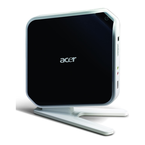
Page 13: System Components
This section is a virtual tour of the system’s interior and exterior components. Front Panel Component e-SATA port Microphone-in jack Headphone/Speaker-out/line-out jack Media card reader (4 in 1: XD/SD/MMC/MS) SPDIF Acer Logo USB 2.0 port Power Button USB 2.0 port Chapter 1... -
Page 14: Rear Panel
Rear Panel Component 4 X USB 2.0 port LAN Connector HDMI Connector D-sub Connector DC-in Jack Chapter 1... -
Page 15: Power Management Function(Acpi Support Function)
Power Management Function(ACPI support function) Device Standby Mode Independent power management timer for hard disk drive devices(0-15 minutes,time step=1minute). • Hard Disk drive goes into Standby mode(for ATA standard interface). • Disable V-sync to control the VESA DPMS monitor. • Resume method:device activated (keyboard for DOS, keyboard &mouse for Windows. -
Page 16: System Utilities
System Utilities CMOS Setup Utility CMOS setup is a hardware configuration program built into the system ROM, called the complementary metal- oxide semiconductor (CMOS) Setup Utility. Since most systems are already properly configured and optimized, there is no need to run this utility. You will need to run this utility under the following conditions. When changing the system configuration settings When redefining the communication ports to prevent any conflicts When modifying the power management configuration... -
Page 17: Entering Cmos Setup
Entering CMOS setup Turn on the server and the monitor. If the server is already turned on, close all open applications, then restart the server. During POST, press Delete. If you fail to press Delete before POST is completed, you will need to restart the server. The Setup Main menu will be displayed showing the Setup’s menu bar. -
Page 18: Setup Utility Menus
Setup Utility Menus The Setup Main menu includes the following main setup categories. Parameter Description Product Information This page shows the relevant information of the main board Standard CMOS Features This setup page includes all the items in standard compatible BIOS Advance BIOS Features CMOS This setup page includes all the items of Award special enhanced features Advanced Chipset Features... -
Page 19: Product Information
Product Information The Product Information menu displays basic information about the system. These entries are for your reference only and are not user-configurable. Parameter Description Processor Type Type of CPU installed on the system. Processor Speed Speed of the CPU installed on the system. System Memory Total size of system memory installed on the system. -
Page 20: Standard Cmos Features
Standard CMOS Features Parameter Description System Date Set the date following the weekday-month-day-year format. System Time Set the system time following the hour-minute-second format. AHCI Port 0/1 Press Enter to view detailed device information. Halt On Determines whether the system will stop for an error during the POST. Chapter 2 Option All, But Keyboard... - Page 21 Advanced BIOS Feature Parameter Description Quick Boot Allows you to decrease the time it takes to boot the computer by shortening or skipping certain standard booting process. Quiet Boot When enabled, the BIOS splash screen displays during startup. When disabled, the diagnostic screen displays during startup. 1st/2nd/3rd/4th Boot Device Specifies the boot order from the available devices.
-
Page 22: Advanced Chipset Features
Advanced Chipset Features Parameter Description Intel XD Bit When enabled, the processor disables code execution when a worm attempts to insert a code in the buffer preventing damage and worm propagation. When disabled, the processor forces the Execute Disable (XD) Bit feature flag to always return to 0. -
Page 23: Integrated Peripherals
Integrated Peripherals Parameter Description Onboard SATA Controller Enables or disables the onboard SATA controller. Onboard SATA Mode Select an operating mode for the onboard SATA. Onboard USB Controller Enables or disables the onboard USB controller. Legacy USB Support Enables or disables support for legacy USB devices. Onboard Audio Controller Enables or disables the onboard audio controller. -
Page 24: Power Management Setup
Power Management Setup Parameter Description ACPI Suspend Mode Select an ACPI state. Deep Power off Mode Enables or disables the Deep power off mode Power On by RTC Alarm Enables or disables to wake up the system by time setting Power On by PCIE Devices Enables or disables to wake up the system from a power saving mode through an event on PCI Express device. -
Page 25: Pc Health Status
PC Health Status Parameter Description CPU Shutdown Temperature Enables or disables the system shutdown when the system is over hot. Smart FAN Enables or disables the smart system fan control function. Option Enabled Disabled Enabled Disabled Chapter 2... - Page 26 Frequency/Voltage Control Parameter Description Spread Spectrum Enables or disables the reduction of the mainboard’s EMI. Note: Remember to disable the Spread Spectrum feature if you are overclocking. A slight jitter can introduce a temporary boost in clock speed causing the overclocked processor to lock up. Chapter 2 Option Enabled...
-
Page 27: Bios Security Features
BIOS Security Features Parameter Description Supervisor Password Indicates the status of the supervisor password. User Password Indicates the status of the user password. Change Supervisor Supervisor password prevents unauthorized access to the BIOS Setup Utility. Press Enter to change the Supervisor password. Password Setting a supervisor password Use the up/down arrow keys to select Change Supervisor Password menu then press Enter. -
Page 28: Load Default Settings
Load Default Settings The Load Default Settings menu allows you to load the default settings for all BIOS setup parameters. Setup defaults are quite demanding in terms of resources consumption. If you are using low-speed memory chips or other kinds of low-performance components and you choose to load these settings, the system might not function properly. - Page 29 Save & Exit Setup The Save & Exit Setup menu allows you to save changes made and close the Setup Utility. Chapter 2...
-
Page 30: Exit Without Saving
Exit Without Saving The Exit Without Saving menu allows you to discard changes made and close the Setup Utility. Chapter 2... -
Page 31: System Disassembly
System Disassembly This chapter contains step-by-step procedures on how to disassemble the desktop computer for maintenance and troubleshooting. Disassembly Requirements To disassemble the computer, you need the following tools: Wrist grounding strap and conductive mat for preventing electrostatic discharge Flat-blade screwdriver Philips screwdriver Hex screwdriver Plastic flat-blade screwdriver... -
Page 32: Pre-Disassembly Procedure
Pre-disassembly Procedure Before proceeding with the disassembly procedure, perform the steps listed below: Turn off the system and all the peripherals connected to it. Unplug the power cord from the power outlets. Unplug the power cord from the system. Unplug all peripheral cables from the system. Place the system unit on a flat, stable surface. -
Page 33: Removing The Side Panel
Removing the Side Panel Put the Computer on the worktable lightly. Release side cover with 1 screws then remove side cover. Chapter 3... -
Page 34: Removing Front D/B
Removing Front D/B Use hand to loosen both sides the clasp. Lift the D/B away from the main board. Chapter 3... -
Page 35: Removing Cpu Fan
Removing CPU fan WARNING:The heat sink becomes very hot when the system is on. NEVER touch the heat sink with any metal or with your hands. Use screwdriver to loosen the three screws and disconnect fan cable. Remove CPU fan from CPU cooler. Chapter 3... -
Page 36: Removing Cpu Cooler
Removing CPU Cooler WARNING:The heat sink becomes very hot when the system is on. NEVER touch the heat sink with any metal or with your hands. Use screwdriver to loosen the four screws.Remove CPU fan from CPU cooler. Remove CPU cooler. Chapter 3... -
Page 37: Removing Wireless Lan
Removing wireless LAN Remove wireless LAN antenna cable Disconnect aux_ antenna cable (gray) from"AUX" connector of wireless LAN? Disconnect main_ antenna cable (black) from"MAIN" connector. Remove wireless LAN. Use hand to loosen both sides clip take off wireless LAN card from M/B MINI-PCIE" connector. Chapter 3... -
Page 38: Removing M/B
Removing M/B Remove the four screws that secure the main board to the chassis. Lift the board from the chassis. Chapter 3... -
Page 39: Removing The Hard Disk Drive
Removing the Hard Disk Drive Use screwdriver to loosen the four screws. Remove HDD from Main board. Chapter 3... -
Page 40: Removing Memory
Removing Memory Remove Memory from SODIMM. Remove the second Memory from SODIMM2 (Optional by SKU). Chapter 3... -
Page 41: System Troubleshooting
System Troubleshooting This chapter provides instructions on how to troubleshoot system hardware problems. Hardware Diagnostic Procedure Please refer to generic troubleshooting guide for troubleshooting information relating to following topics: Power-On Self-Test (POST) POST Error Messages List Error Symptoms List Undetermined Problems Power-On Self-Test (POST) Each time you turn on the system, the Power-on Self Test (POST) is initiated. - Page 42 Post Checkpoints List: The list may vary accordingly depending on your BIOS Checkpoint Test CMOS R/W functionality Early chipset initialization: -Disable shadow RAM -Disable L2 cache (socket 7 or below) -Program basic chipset registers Detect memory -Auto-detection of DRAM size, type and ECC. -Auto-detection of L2 cache (socket 7 or below) Expand compressed BIOS code to DRAM Call chipset hook to copy BIOS back to E000 &...
- Page 43 Checkpoint Program chipset default values into chipset. Chipset default values are MODBINable by OEM customers. Reserved Initial Early_Init_Onboard_Generator switch. Reserved Detect CPU information including brand, SMI type (Cyrix or Intel) and CPU level (586 or 686) Reserved Reserved Initial interrupts vector table. If no special specified, all H/W interrupts are directed to SPURIOUS_INT_HDLR &...
- Page 44 Checkpoint Reserved Reserved 1. Program MTRR of M1 CPU. 2. Initialize L2 cache for P6 class CPU & program CPU with proper cacheable range. 3. Initialize the APIC for P6 class CPU. 4. On MP platform, adjust the cacheable range to smaller one in case the cacheable ranges between each CPU are not identical.
- Page 45 Checkpoint Turn on L2 cache Reserved Program chipset registers according to items described in Setup& Auto configuration table. Reserved 1. Assign resources to all ISA PnP devices. 2. Auto assign ports to onboard COM ports if the corresponding item in Setup is set to “AUTO”...
- Page 46 Checkpoint 1. USB final Initialization 2. NET PC: Build SYSID structure 3. Switch screen back to text mode. 4. Set up ACPI table at top of memory. 5. Invoke ISA adapter ROMs. 6. Assign IRQs to PCI devices 7. Initialize APM 8.
-
Page 47: Post Error Messages List
POST Error Messages List If you cannot run the diagnostics program tests but did receive a POST error message, use "POST Error Messages List" to diagnose system problems. If you did not receive any error message, look for a description of your error symptoms in "Error Symptoms List"... - Page 48 BIOS Messages Hard disk(s) diagnosis fail Keyboard Error Or No Keyboard Present Keyboard is locked out - Unlock the key Memory Test: Memory test fail Override enabled - Defaults loaded Press TAB to show POST screen Primary master hard disk fail Primary slave hard disk fail Secondary master hard disk fail Secondary slave hard disk fail...
-
Page 49: Error Symptoms List
Error Symptoms List NOTE: To diagnose a problem, first find the error symptom in the left column. If directed to a check procedure, replace the FRU indicated in the check procedure. If no check procedure is indicated, the first Action/ FRU listed in right column is the most likely cause. - Page 50 Error Symptom Diskette drive does not work. Diskette drive read/write error. Diskette drive LED comes on for more than 2 minutes when reading data. Diskette drive LED fails to light, and the drive is unable to access for more than 2 minutes. Diskette drive test failed.
- Page 51 Error Symptom CD/DVD-ROM drive LED doesn't come on but works normally. CD/DVD-ROM drive LED flashes for more than 30 seconds before LED shutting off. Software asks to reinstall disc.Software displays a reading CD/DVD error. CD/DVD-ROM drive cannot load or eject when the system is turned on and its eject button is pressed and held.
- Page 52 Error Symptom Video memory test failed.Video adapter failed. Display problem: -Incorrect colors No high intensity Missing, broken, or incorrect characters Blank monitor (dark) Blank monitor (bright) Distorted image Unreadable monitor Other monitor problems Display changing colors. Display problem not listed above (including blank or illegible monitor).
- Page 53 Error Symptom Executing software shutdown from Windows98 Start menu does not turn off the system. (Only pressing power switch can turn off the system). No system power, or power supply fan is not running. Any other problems. Chapter 4 Action/FRU 1.Load default settings.
-
Page 54: Undetermined Problems
Check all cables and connectors for proper installation. If the jumpers, switches and voltage settings are correct, remove or disconnect the following, one at a time: 10. Non-Acer devices External devices Any adapter card (modem card, LAN card or video card, if installed) -
Page 55: Jumper And Connector Information
Jumper and Connector Information Jumper Setting The section explains how to set jumper for correct configuration of the mainboard. Setting Jumper Use the motherboard jumpers to set system configuration options. Jumpers with more numbered. When setting the jumpers, ensure that the jumper caps are Placed on the correct pins. System Board Jumper Setting System Board Jumper Setting Jumper/Header Name... - Page 56 Jumper/Header Name USB CONNECTORS (Stacked)(Black) REAR_USB1, REAR_USB2 Function Front panel header Definition 1: GND 2: F_USBPWR 3: USB_P5+ 4: USB_P5- 5: GND 6: F_USBPWR* 7: USB_P4+ 8: USB_P4- 9: FP_9(PU 5V_S0) 10: KEY 11: PWRBTNJ 12: LEDP 13: GND 14: PMSLED Chapter 5...
- Page 57 LAN1 NOTE: Pins 1-12 for RJ-45 LAN Jack pin definition, 13-16 for LAN LED definition Audio Back Panel Connectors (Vertical) AUDIO1 (MIC IN /Pink in Color) AUDIO2 (LINE OUT /Lime in Color) Chapter 5...
- Page 58 DCIN VGA(D-SUB) Chapter 5...
- Page 59 HDMI eSATA CONN Chapter 5...
- Page 60 SATA CONN Chapter 5...
- Page 61 Card reader Signal Name SD-1 SD_DAT3 SD-2 SD_CMD SD-3 SD-4 CARD_3V3 SD-5 SD_CLK SD-6 SD-7 MS_SD_DAT0 SD-8 SD_DAT1 SD-9 SD_DAT2 SD-CD1 GND SD-CD2 SD_CD# SD-W P1 GND SD-W P2 SD_W P MS-1 MS-2 MS_BS MS-3 MS_D1 MS-4 MS_SD_DAT0 MS-5 MS_D2 MS-6 MS_INS# MS-7...
- Page 62 Spidif Chapter 5...
-
Page 63: Fru (Field Replaceable Unit) List
To scrap or to return the defective parts, follow the local government ordinance or regulations on how to dispose it properly, or follow the rules set by your regional Acer office on how to return it. This document will be updated as more information about the FRU list becomes available. -
Page 64: Aspire R3610 Exploded Diagram
Aspire R3610 Exploded Diagram NOTE: This section will be updated when more information becomes available. PART NO Bot-cover Cover-pannel SHEETMETAL-TOP ACER-1L-MB-LOYOUT ANTENNA_P_7 1L-Power-Switch SHEETMETAL-BOT PART NO 01-Main-base POWER-BUTTON 2009_Acer Top-Cover ANTENNA_B_8 V-STAND Chapter 6... -
Page 65: Aspire R3610 Fru List
Aspire R3610 FRU List Category Mainboard R3610 nVidia Proprietary LF MCP7A- ION,W/ eSATA, W/ HDMI,S/PDIF ,Atom330 Cooler w/i 7012 blower (for Atom 230) Hornet a/p/g N330 FXN PKP710G w/i sunon fan Memory so-DIMM GU331G0ALEPR612C6CE/DDRII800/ Memory NANYA SO-DIMM DDRII 800 1GB NT1GT64UH8D0FN-AD LF 64*16 0.07um... - Page 66 Category HGST 2.5" 5400rpm 160GB HTS543216L9A300 Falcon-B SATA LF F/W:C40C SEAGATE 2.5" 5400rpm 160GB ST9160310AS Crockett SATA LF F/W:0303 WD 2.5" 5400rpm 160GB WD1600BEVT-22ZCTO ML160 SATA LF F/W:11.01A11 HDD HGST 2.5" 5400rpm 250GB HTS545025B9A300 Panther B SATA LF F/ W:C60F HDD SEAGATE 2.5"...
- Page 67 Category Chicony Mouse RF2.4 MGR0919 with Receiver USB Optical Mouse mouse USB M-U0005 Speaker Neosonica mini speaker USB White webcam webcam+stand air mouse + controller(game pad) Cywee 3D stick mouse Mouse Z Mounting 1L Hornet Mounting kit for a/p/g Remote controller EMEA Vista RC EMEA Vista MCE US Vista MCE...
- Page 68 Category Receiver w/o IR Blaster Receiver w/ IR Blaster USB Keyboard Keyboard CHICONY KU-0906 USB 104KS White Keyboard CHICONY KU-0906 USB 104KS White Traditional Chinese Keyboard CHICONY KU-0906 USB 104KS White Simplified Chinese Keyboard CHICONY KU-0906 USB 104KS White US International Keyboard CHICONY KU-0906 USB 104KS White Arabic/English Keyboard CHICONY KU-0906 USB 104KS White...
- Page 69 Category Keyboard CHICONY KU-0906 USB 105KS White Dutch Keyboard CHICONY KU-0906 USB 105KS White Swiss/G Keyboard CHICONY KU-0906 USB 105KS White Belgium Keyboard CHICONY KU-0906 USB 105KS White Icelandic Keyboard CHICONY KU-0906 USB 105KS White Norwegian Keyboard CHICONY KU-0906 USB 104KS White Hebrew Keyboard CHICONY KU-0906 USB 105KS White Polish...
- Page 70 Category Keyboard CHICONY KU-0906 USB 105KS White Nordic Wireless KB Keyboard CHICONY KG-0917 RF2.4 104KS White US Keyboard CHICONY KG-0917 RF2.4 104KS White Traditional Chinese Keyboard CHICONY KG-0917 RF2.4 104KS White Simplified Chinese Keyboard CHICONY KG-0917 RF2.4 104KS White US International Keyboard CHICONY KG-0917 RF2.4 104KS White Arabic/English Keyboard CHICONY KG-0917 RF2.4 104KS...
- Page 71 Category Keyboard CHICONY KG-0917 RF2.4 105KS White Norwegian Keyboard CHICONY KG-0917 RF2.4 104KS White Hebrew Keyboard CHICONY KG-0917 RF2.4 105KS White Polish Keyboard CHICONY KG-0917 RF2.4 105KS White Slovenian Keyboard CHICONY KG-0917 RF2.4 105KS White Slovak Keyboard CHICONY KG-0917 RF2.4 104KS White Russian Keyboard CHICONY KG-0917 RF2.4 105KS White Hungarian...