Miele CVA 610 Technical Information
Coffee systems
Hide thumbs
Also See for CVA 610:
- Technical information (107 pages) ,
- Operating instructions manual (72 pages) ,
- Operating instructions manual (20 pages)
Table of Contents
Advertisement
Quick Links
Advertisement
Table of Contents

Related Manuals for Miele CVA 610


Summary of Contents for Miele CVA 610
- Page 1 TECHNICAL INFORMATION CVA 610/CVA 615 Coffee Systems © 2012 Miele USA...
- Page 2 Technical Data ...................... 9 1.2.1 Product Dimensions ..................9 1.2.2 Electrical Information ..................9 1.3 Component Layouts .................... 10 1.3.1 CVA 610 ....................... 10 1.3.2 CVA 615 ....................... 11 2.0 Installation ......................12 3.0 ...
- Page 3 CVA 610/CVA 615 Coffee Systems Technical Information 4.20.1 Power Electronic (CVA 615) ................. 35 4.20.2 CPU Electronic (CVA 615) ................36 4.20.3 CVA 610 CPU Electronic ................37 5.0 Service and Maintenance ................. 38 5.1 ...
- Page 4 Figure 1-2: CVA Controls ....................7 Figure 1-3: Appliance Overview (Interior) ................. 8 Figure 1-4: CVA 61x Dimensions ..................9 Figure 1-5: CVA 610 Component Layout ................ 10 Figure 1-6: CVA 615 Component Layout ................ 11 Figure 2-1: Operating Manual ..................12 Figure 2-2: Installation Information .................
- Page 5 Figure 5-8: Overflow Switch Actuator Float ..............43 Figure 5-9: Overflow Switch .................... 44 Figure 5-10: Light Cover Access and Removal (CVA 610) ..........44 Figure 5-11: Light Tube Removal (CVA 610) ..............45 Figure 5-12: Starter Removal ..................45 Figure 5-13: Rear Door Panel Removal ................
- Page 6 Figure 5-43: Removing the Lip Seal ................68 Figure 5-44: Valve Screws ....................68 Figure 5-45: Underside View of the CVA 610 with Base Plate and Drip Tray Removed 69 Figure 5-45: Removing the Beans Container ..............69 Figure 5-46: Beans Container Guide ................70 Figure 5-47: Grinder Disassembly ..................
-
Page 7: Construction And Design
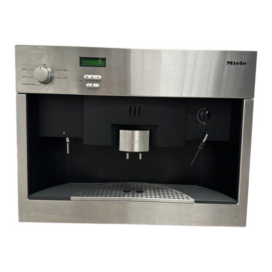
CVA 610/CVA 615 Coffee Systems Technical Information Construction and Design Appliance Overview Figure 1-1: Appliance Overview (Front) ① Hot-water dispenser ② Coffee dispensers (height-adjustable) ③ Handle to open appliance front ④ Steam selector ⑤ Steam nozzle with milk frother ⑥... -
Page 8: Figure 1-3: Appliance Overview (Interior)
CVA 610/CVA 615 Coffee Systems Technical Information Figure 1-3: Appliance Overview (Interior) ⑫ Beans container ⑬ Slide control to select fineness of ground coffee ⑭ Slide control to select quantity of ground coffee ⑮ Water tank ⑯ Waste container ⑰... -
Page 9: Technical Data
1.2.2 Electrical Information The CVA 610 is equipped with a 6’ (1.8m) power cord and a molded NEMA 6-15P plug for connection to a 240 (208) V, 15A, 60Hz power supply. The CVA 615 is equipped with a 6’ (1.8m) power cord with a NEMA 5-15P molded... -
Page 10: Component Layouts
CVA 610/CVA 615 Coffee Systems Technical Information Component Layouts 1.3.1 CVA 610 Figure 1-5: CVA 610 Component Layout 1 Steam valve switch 16 Flow meter 2 Door magnet 17 Interference suppression capacitor 3 Fluorescent bulb 18 CPU electronic 4 Starter... -
Page 11: Cva 615
CVA 610/CVA 615 Coffee Systems Technical Information 1.3.2 CVA 615 Figure 1-6: CVA 615 Component Layout 1 Steam valve switch 16 Flow meter 2 Door magnet 17 Interference suppression capacitor 3 Halogen bulb (2) 18 Power electronic 4 Control electronic... -
Page 12: Installation
CVA 610/CVA 615 Coffee Systems Technical Information Installation Refer to the “Installation” section of the operating manual. Figure 2-1: Operating Manual... -
Page 13: Figure 2-2: Installation Information
CVA 610/CVA 615 Coffee Systems Technical Information Warning! Make sure that power is not supplied to the appliance while installation or maintenance work is performed. Disconnect the power supply to the work area by unplugging the appliance, tripping the circuit breaker or removing the fuse. -
Page 14: Commission And Operation
CVA 610/CVA 615 Coffee Systems Technical Information Commission and Operation General Operation 3.1.1 Preparing Coffee Place a cup under both coffee dispensers. See Figure 3-1. Figure 3-1: Coffee Cup Placed Under Both Dispensers Press the desired coffee button once. Figure 3-2: Pressing the Coffee Button The coffee will be prepared. -
Page 15: Steam Control
CVA 610/CVA 615 Coffee Systems Technical Information 3.1.3 Steam Control Caution: The steam from the appliance is extremely hot; use caution to prevent burns. Turn the steam ON by turning the steam selector counterclockwise. Turn the steam OFF by turning the steam selector clockwise. -
Page 16: Adjusting The Coffee Grinder
CVA 610/CVA 615 Coffee Systems Technical Information Note: If the hot-water feature has been activated, the flow of hot water will stop automatically once a predetermined amount of hot water has passed through the system 3.1.5 Adjusting the Coffee Grinder Controls: Slide to the left for finer grinding. -
Page 17: Filling The Water Tank
CVA 610/CVA 615 Coffee Systems Technical Information Figure 3-9: Filling the Beans Container Important! Only put pure espresso or coffee bean in the container. Anything else, including ground coffee, hot cocoa, instant coffee, or treated coffee beans (flavorings, caramel, or sugar) will damage the grinder. -
Page 18: Description Of Function
CVA 610/CVA 615 Coffee Systems Technical Information Description of Function Door Switch (S24) The door switch (Figure 4-1, Item 1) interrupts the main power circuit when the door is opened. Figure 4-1: Door Contact Switch (S24) Overflow Switch (B8/3) The overflow switch is mounted to the bottom of the casing. The associated float (with internal magnet) is located within the drip tray. -
Page 19: Removal From The Appliance
CVA 610/CVA 615 Coffee Systems Technical Information 4.3.2 Removal from the Appliance The brew unit must be in the “home” position (see Figure 4-2, Item 1) before it can be removed from the appliance. Figure 4-2: Brew Unit in the “Home” Position 4.3.3... -
Page 20: Brewing Procedure
CVA 610/CVA 615 Coffee Systems Technical Information 1 Drive shaft socket 2 Water connection socket 3 Locking mechanism switch lug 4 Brew unit present switch 5 Water nozzle 6 Drive shaft Figure 4-3: Brew Unit Drive and Water Connections Brewing Procedure 1. -
Page 21: Figure 4-5: Brew Unit Components
CVA 610/CVA 615 Coffee Systems Technical Information the top filter (Figure 4-5, Item 2) and bottom filter (Figure 4-5, Item 5). 6. The water pump is energized to pump the water through the hot water/coffee nozzle and into the brew unit via the water connection socket (Figure 4-5, Item 4). -
Page 22: Waste Container
CVA 610/CVA 615 Coffee Systems Technical Information Waste Container After coffee has been prepared, the compressed coffee grounds “puck” falls into the waste container. The electronic monitors the number of the compressed pucks. After a specific amount is reached, the message “Empty waste container” is displayed. -
Page 23: Water Tank
CVA 610/CVA 615 Coffee Systems Technical Information In service mode, the top line of the display shows the switches that have been activated. A “5” is displayed when the waste container is installed and the switch is actuated. For further information, refer to Section 6.2. -
Page 24: Figure 4-10: Water Level Switch
CVA 610/CVA 615 Coffee Systems Technical Information Figure 4-10: Water Level Switch The actuating magnet for the water level switch is located within the float. The float is then installed into the water tank, as shown in Figure 4-11, Item 1. -
Page 25: Grinder Assembly
CVA 610/CVA 615 Coffee Systems Technical Information passing through the water pump is registered via the flow meter and monitored by the electronic. After most of the 800 milliliters is calculated as being used, the display shows, “Fill water tank.” To prevent the water pump from running dry, approximately 90 to 200 milliliters (3 to 7 ounces) of water remains in the tank. -
Page 26: Grinder Overload Protection
CVA 610/CVA 615 Coffee Systems Technical Information 4.10 Grinder Overload Protection If the grinder becomes blocked by a foreign object (e.g., stone or pebble), the slip coupling will interrupt the drive between the motor and the grinder. The grinder motor (Figure 4-12, Item 1) drives the mounting (Figure 4-12, Item 3) via the carriers (Figure 4-12, Item 2). -
Page 27: Ground Coffee Dispensing
CVA 610/CVA 615 Coffee Systems Technical Information 4.11 Ground Coffee Dispensing By adjusting the dispenser lever (Figure 4-14, Item 1), the position of the dispensing switch (Figure 4-14, Item 2) is modified. The change results in a change in volume of the dispenser container, so the quantity of ground coffee changes. -
Page 28: Dispenser Switch
CVA 610/CVA 615 Coffee Systems Technical Information To fill the brew unit, the dispensing solenoid is energized twice and the dispenser flap opens twice. The ground coffee drops from the dispenser container into the brew unit. If the dispenser container is not filled because there are no coffee beans in the bean holder, the dispenser switch is not activated. -
Page 29: Water Pump
CVA 610/CVA 615 Coffee Systems Technical Information switches are monitored by the electronic to determine the position of the brew unit. 1 Home position switch 2 Home position switch actuator 3 Worm gear 4 Brew unit drive motor 5 Brew position switch actuator... -
Page 30: Flow Meter
CVA 610/CVA 615 Coffee Systems Technical Information 4.16 Flow Meter All water taken from the water tank flows through the flow meter. The flow meter sends signals to the electronic proportional to the quantity of water passing through The electronic then establishes the quantity of water that has flowed and stores the figure. -
Page 31: Figure 4-19: Coffee/Hot-Water Heater (1R1, 1R2)
CVA 610/CVA 615 Coffee Systems Technical Information 1 Heater element 2 Connector 3 Temperature monitor 4 Temperature safety fuse 5 PTC temperature sensor 6 Temperature safety fuse 7 Small heater element 8 Connector 9 Mounting 10 Outlet Figure 4-19: Coffee/Hot-Water Heater (1R1, 1R2) -
Page 32: Water Path
CVA 610/CVA 615 Coffee Systems Technical Information 4.19 Water Path Figure 4-21: Water Path 1 Water tank 8 Coffee heater 2 Sealing ring 9 Water valve to brew unit 3 Water filter 10 Steam valve (solenoid) 4 Flow meter 11 Hot-water valve (solenoid) -
Page 33: Water Path – Hot Water
CVA 610/CVA 615 Coffee Systems Technical Information 4.18.3 Water Path – Hot Water The water pump moves water under pressure through the flow meter, through the coffee heater, and then via the hot-water valve to the hot-water outlet. 4.18.4 Water Path - Steam The pump moves water under pressure via the flow meter and through the coffee heater. -
Page 34: Figure 4-22: Water Valve
CVA 610/CVA 615 Coffee Systems Technical Information Figure 4-22: Water Valve... -
Page 35: Electronic Assemblies
CVA 610/CVA 615 Coffee Systems Technical Information 4.20 Electronic Assemblies 4.20.1 Power Electronic (CVA 615) JP12 JP11 Front of Appliance To CPU Board JP1-1 JP10 FUSES F1: 3.15A F2: 2A Transformer F3: 3.15A F4: 12A F5: 12A F6: 360mA To CPU Board... -
Page 36: Cpu Electronic (Cva 615)
CVA 610/CVA 615 Coffee Systems Technical Information 4.20.2 CPU Electronic (CVA 615) Front of Appliance From JP41 Power Board JP31 JP40 JP28 JP36 Display Board JP29 JP25 JP27 JP26 JP33 JP32 Figure 4-24: CVA 615 CPU Electronic... -
Page 37: Cva 610 Cpu Electronic
CVA 610/CVA 615 Coffee Systems Technical Information 4.20.3 CVA 610 CPU Electronic JP17 JP24 JP19 JP23 JP20 JP12 JP15 Transformer JP11 JP16 Front of Appliance JP21 JP22 Figure 4-25: CVA 610 CPU Electronic... -
Page 38: Service And Maintenance
CVA 610/CVA 615 Coffee Systems Technical Information Service and Maintenance Danger! To avoid the risk of electrical shock, the appliance should be disconnected from the power source before any service procedures are performed. Lid Removal 1. Remove the lid screws, as shown in Figure 5-1. -
Page 39: Cpu Electronic Removal (Cva 610)
CVA 610/CVA 615 Coffee Systems Technical Information Figure 5-2: Interference Suppression Filter Mounting Location CPU Electronic Removal (CVA 610) 1. Remove the lid; see Section 5.1. 2. Disconnect the door switch connections. 3. Disconnect all connections from the CPU electronic. -
Page 40: Adjustment Slide Switch Frame Removal
CVA 610/CVA 615 Coffee Systems Technical Information 5. Remove the rear panel upwards. Note: In some CVA 610 models, there may be an additional screw securing the rear panel to the steam heater mounting bracket. Figure 5-3: Rear Panel Removal Adjustment Slide Switch Frame Removal 1. -
Page 41: Door Contact Switch (S24) Removal
CVA 610/CVA 615 Coffee Systems Technical Information Door Contact Switch (S24) Removal 1. Remove the lid; see Section 5.1. 2. Open the door. 3. Disconnect the door switch connections. 4. Press the switch’s locking tabs inward with a small flathead screwdriver. -
Page 42: Drip Tray Removal
CVA 610/CVA 615 Coffee Systems Technical Information Figure 5-6: Base Plate Removal 5.10 Drip Tray Removal 1. Remove the lid (Section 5.1), interference suppression filter (Section 5.2) and rear panel (Section 5.6). 2. Remove the base plate; see Section 5.9. -
Page 43: Overflow Switch Actuator Float Removal
CVA 610/CVA 615 Coffee Systems Technical Information 5.11 Overflow Switch Actuator Float Removal 1. Remove the lid (Section 5.1), interference suppression filter (Section 5.2) and rear panel (Section 5.6). 2. Remove the base plate; see Section 5.9. 3. Remove the float. See Figure 5-8, Item 1. -
Page 44: Fluorescent Light Removal (Cva 610)
Fluorescent Light Removal (CVA 610) 1. Open the door. 2. Unclip the light cover (see Figure 5-10) and remove it. Figure 5-10: Light Cover Access and Removal (CVA 610) 3. Turn the light tube 90° towards you to remove. See Figure 5-11. -
Page 45: Light Starter Removal (Cva 610)
CVA 610/CVA 615 Coffee Systems Technical Information Figure 5-11: Light Tube Removal (CVA 610) 5.14 Light Starter Removal (CVA 610) 1. Open the door. 2. Unclip the light cover and remove it. 3. Turn the starter counterclockwise to remove (Figure 5-12 shows the view from the outside of the appliance door). -
Page 46: Rear Door Panel Removal
CVA 610/CVA 615 Coffee Systems Technical Information 5.16 Rear Door Panel Removal 1. Open the door. 2. Remove the 8 screws securing the panel’s trim pieces (Figure 5-13, Items 1 and 2). 3. Remove the 2 screws securing the middle of the panel (Figure 5-13, Item 3). -
Page 47: Selector Switch Removal
CVA 610/CVA 615 Coffee Systems Technical Information 5.18 Selector Switch Removal 1. Open the door. 2. Remove the rear door panel and fascia panel cover; see Sections 5.15 and 5.16. 3. Disconnect the connections from the selector switch. 4. Remove the switch knob (Figure 5-15, Item 9). -
Page 48: Dispenser Assembly Removal
CVA 610/CVA 615 Coffee Systems Technical Information Figure 5-16: Selection/Display Electronic Removal 1 Pushbuttons 2 Display electronic 3 Display electronic screws 4 Selection-display electronic interface 5 Control and power electronics connection 6 Selection electronic screws 7 Selection electronic 5.20 Dispenser Assembly Removal 1. -
Page 49: Dispenser Assembly Installation
CVA 610/CVA 615 Coffee Systems Technical Information Figure 5-17: Dispenser Assembly Components 1 Screw 6 Connection hose 2 Drip tray (select models) 7 Outlet 3 Underlay 8 Retainers 4 Outlet 9 Dispenser assembly 5 Cable holder 10 Cover 5.21 Dispenser Assembly Installation 1. -
Page 50: Steam Valve And Steam Valve Switch (S79) Removal
CVA 610/CVA 615 Coffee Systems Technical Information 5.22 Steam Valve and Steam Valve Switch (S79) Removal 1. Open the door. 2. Remove the rear door panel and fascia panel cover; see Sections 5.15 and 5.16. 3. Pull off the switch knob (Figure 5-18, Item 8). -
Page 51: Hot-Water Valve (Y12) Removal
CVA 610/CVA 615 Coffee Systems Technical Information 4. Remove the screws securing the mounting bracket to the rear door panel (Figure 5-19, Item 4). 5. Remove the mounting bracket (Figure 5-19, Item 5) and disconnect the ground wire. 6. Unscrew the sleeve (Figure 5-19, Item 1) from the connector (Figure 5-19, Item 6). -
Page 52: Brew Unit Removal (In Start/Home Position)
CVA 610/CVA 615 Coffee Systems Technical Information 7. Press the Small Coffee button 1 time. 8. Press the Medium Coffee button 2 times. The following is displayed: 1 COFFEE IMPULS. 350 9. Observe the numeric value in the lower right corner of the display. It should be approximately 350. -
Page 53: Figure 5-20: Brew Unit
CVA 610/CVA 615 Coffee Systems Technical Information 7. Grasp the brew unit handle and pull the brew unit out until the connection socket on the brew unit (Figure 5-20, Item 1) unsnaps from the brew unit and remains inside the appliance attached to the water nozzle. -
Page 54: Brew Unit Installation
CVA 610/CVA 615 Coffee Systems Technical Information Figure 5-21: Brew Unit Connection Socket 5.28 Brew Unit Installation Slide the brew unit into position in the appliance until the locking mechanism engages with the drive mounting plate. Note: Do not press the part marked PRESS during the installation of the brew unit. -
Page 55: Brew Unit Filter Cleaning
CVA 610/CVA 615 Coffee Systems Technical Information Figure 5-22: Brew Unit Removal for Cleaning 3. Pull outward to remove the brew unit (Figure 5-22, Item 2). 4. Clean the brew unit thoroughly under warm running water without detergent. 5. Rub away coffee residues from the steel filters with a sponge. -
Page 56: Brew Unit Degreasing Via The Rinse Cycle
CVA 610/CVA 615 Coffee Systems Technical Information 5.31 Brew Unit Degreasing via the Rinse Cycle Note: The natural oil found in coffee can cause the brew unit to clog. The message “Rinsing Cycle” will flash in the message window after 500 cups to remind you to clean the brew unit using cleaning tablets. -
Page 57: Brew Unit Lubrication
CVA 610/CVA 615 Coffee Systems Technical Information 5.32 Brew Unit Lubrication 1. Remove the brew unit; see Section 5.26. Note: Check that the brew unit is in the basic position with the funnel slightly lifted and the socket in the vertical position. -
Page 58: Brew Unit Output Removal
CVA 610/CVA 615 Coffee Systems Technical Information Figure 5-27: Moving the Brew Unit to the Home Position 4. Figure 5-28 shows the “home” position after resetting. The brew unit can now be re-installed into the appliance. Figure 5-28: Brew Unit in Reset Position 5.34... -
Page 59: Brew Unit Funnel Removal
CVA 610/CVA 615 Coffee Systems Technical Information Figure 5-29: Brew Unit Output and Handle 5.36 Brew Unit Funnel Removal 1. Remove the brew unit; see Section 5.26. 2. Press the funnel locking tab (Figure 5-30, Item 1), so that the funnel is no longer raised. -
Page 60: Brew Unit Ram - Service
CVA 610/CVA 615 Coffee Systems Technical Information Figure 5-31: Brew Unit Spring Location and Holder 5.37 Brew Unit Ram - Service 1. Remove the brew unit from the appliance; see Section 5.26. 2. Remove the funnel; see Section 5.36. 3. Remove the bottom filter screw and filter (Figure 5-34, Items 1 and 2). -
Page 61: Figure 5-32: Releasing The Ram On The Underside Of The Brew Unit
CVA 610/CVA 615 Coffee Systems Technical Information Figure 5-32: Releasing the Ram on the Underside of the Brew Unit 6. Push the ram upward, the turn the brew unit right-side up and pull the ram out of the brewing chamber. -
Page 62: Accessing The Brew Unit Drive
CVA 610/CVA 615 Coffee Systems Technical Information 1 Filter screw 2 Filter 3 Lubrication points Figure 5-34: Ram Assembly 5.38 Accessing the Brew Unit Drive 5.38.1 CVA 610 1. Disconnect the power. Allow the appliance to cool. 2. Remove the brew unit from the appliance; see Section 5.26. -
Page 63: Cva 615
CVA 610/CVA 615 Coffee Systems Technical Information Figure 5-35: Screws Securing the Brew Unit Drive Cover (CVA 610) 5.38.2 CVA 615 1. Disconnect the power. Allow the appliance to cool. 2. Remove the brew unit from the appliance; see Section 5.26. -
Page 64: Figure 5-36: Front Plate Assembly With Retaining Screw Locations
CVA 610/CVA 615 Coffee Systems Technical Information JP35 JP25 JP39 JP41 (ribbon cable) 12. Disconnect the ground connection from the dispenser solenoid. 13. Disconnect the ground connection from the hot-water heater. 14. Remove the CPU electronic (with mounting bracket) and position it toward the rear outside of the appliance. -
Page 65: Figure 5-37: Grinder Retaining Screws
CVA 610/CVA 615 Coffee Systems Technical Information Figure 5-37: Grinder Retaining Screws Figure 5-38: Grinder Retaining Nuts 20. Remove the knobs from the grinder slide controls. 21. Remove the adjustment slide switch frame (Section 5.7). 22. Position the grinder as necessary to access the drive cover and drive unit retaining screws. -
Page 66: Figure 5-39: Upper Front Plate Assembly Retaining Screws
CVA 610/CVA 615 Coffee Systems Technical Information Figure 5-39: Upper Front Plate Assembly Retaining Screws 25. Move the drive assembly cover toward the rear wall of the appliance. 26. Move the drive assembly back while lifting upward to remove it from the appliance. -
Page 67: Water Tank Float Removal
CVA 610/CVA 615 Coffee Systems Technical Information 5.39 Water Tank Float Removal 1. Open the door. 2. Remove the water tank. 3. Remove the cap from the water tank float. See Figure 5-41. 4. Remove the water tank float. Figure 5-41: Water Tank Float Access 5.40... -
Page 68: Lower Section Of Tank Valve - Removal
CVA 610/CVA 615 Coffee Systems Technical Information 4. Remove the seal (Figure 5-43, Item 1). Figure 5-43: Removing the Lip Seal 5.41 Lower Section of Tank Valve - Removal 1. Open the door. 2. Remove the water tank. 3. Remove the tank seal; see Section 5.40. -
Page 69: Beans Container Removal
CVA 610/CVA 615 Coffee Systems Technical Information Figure 5-45: Underside View of the CVA 610 with Base Plate and Drip Tray Removed 5.42 Beans Container Removal 1. Open the door. 2. Remove the beans container end stop screw (Figure 5-46). -
Page 70: Figure 5-46: Beans Container Guide
CVA 610/CVA 615 Coffee Systems Technical Information 5. Remove the guide retaining screws (Figure 5-46, Item 2). 6. Remove the guide and carrier (Figure 5-46, Item 1). Figure 5-46: Beans Container Guide 5.44 Grinder Disassembly Note: The grinder ring and grinder cone must be replaced together. -
Page 71: Figure 5-47: Grinder Disassembly
CVA 610/CVA 615 Coffee Systems Technical Information Figure 5-47: Grinder Disassembly 9. Take off the gasket. 10. Turn the adjustment ring (Figure 5-48, Item 1) counterclockwise until the blue marking aligns with the blue marking on the carrier (Figure 5-48, Item 2). -
Page 72: Figure 5-49: Grinder, Disassembled
CVA 610/CVA 615 Coffee Systems Technical Information Note: When the grinding cone (Figure 5-49, Item 6) is removed, the balls (Figure 5-49, Item 8) may stick to it and then fall off. Lift the cone up slowly! 16. Remove the grinding cone (Figure 5-49, Item 6). -
Page 73: Grinder Assembly And Basic Setting
CVA 610/CVA 615 Coffee Systems Technical Information 5.45 Grinder Assembly and Basic Setting Note: The grinder ring (Figure 5-49, Item 6) and the grinder cone (Figure 5-49, Item 5) should only be replaced together. 1. Replace the felt ring (Figure 5-49, Item 11). -
Page 74: Figure 5-50: Accessing The Grinder For Complete Removal
CVA 610/CVA 615 Coffee Systems Technical Information 6. Remove the adjustment slide switch frame. See Section 5.7. 7. Remove the adjustment lever retaining screws. 8. Remove the adjustment lever. 9. Remove the cover retaining screws (Figure 5-50, Item 4). 10. Remove the cover. -
Page 75: Brew Unit Present Switch Removal
CVA 610/CVA 615 Coffee Systems Technical Information 5.47 Brew Unit Present Switch Removal 1. Remove the lid; see Section 5.1. 2. Remove the rear panel; see Section 5.6. 3. Disconnect the switch (Figure 5-52, Item 2). 4. Press the retainers outward to remove the switch. -
Page 76: Brew Unit Drive – Home Positioning
CVA 610/CVA 615 Coffee Systems Technical Information 5.50 Brew Unit Drive – Home Positioning 1. Remove the brew unit from the appliance; see Section 5.26. 2. Re-install the waste container. 3. Close the door. 4. Turn the selector switch to one of the operating settings. -
Page 77: Water Path Leakage Test
CVA 610/CVA 615 Coffee Systems Technical Information bottom right side of the display; is it 30 or higher? a. No. Check that: Sufficient water is present Water path is clear of calcareous deposits Water lines are clear, not crimped, etc. -
Page 78: Closing Water Path Connections
CVA 610/CVA 615 Coffee Systems Technical Information Figure 5-54: Water System Connections with Clip 5.54 Closing Water Path Connections 1. Check the seals for damage and replace as necessary. 2. Install the seals on the hose. 3. Insert the hose in the connector. -
Page 79: Fault Diagnosis
CVA 610/CVA 615 Coffee Systems Technical Information Fault Diagnosis Programming Mode The programming mode is available for access by the customer. The programming mode offers various functions and/or features to configure. To access the programming mode, simply turn the selector knob to the “Program Mode”... -
Page 80: Table 6-2: Service Mode Functions
CVA 610/CVA 615 Coffee Systems Technical Information 6. Brew unit present switch 7. Water tank level switch 8. Flow meter pulse (not always displayed) A. Drip tray filled (water system fault) 4. Turn the selector switch to the desired function (see Table 6-2). -
Page 81: Displayed Messages
CVA 610/CVA 615 Coffee Systems Technical Information Displayed Messages Displayed Message Information The brew unit is dirty. BREW UNIT BLOCKED The brew unit is blocked. The brew unit is jammed. • Clean/inspect brew unit and check drives. Air is present in the water system. -
Page 82: Fault Diagnosis
CVA 610/CVA 615 Coffee Systems Technical Information Fault Diagnosis Fault Cause Remedy Appliance is not level. Level the appliance. When two cups of coffee/ espresso are being prepared at the same time, the cups are Coffee nozzle is dirty. Clean the coffee nozzle. -
Page 83: Technical Service Bulletins
CVA 610/CVA 615 Coffee Systems Technical Information Technical Service Bulletins CVA 615 Gearbox Replacement; Brew Unit Presence Switch, Check for Proper Wiring When replacing the gearbox in a CVA 615, you should confirm that the brew unit presence switch is wired correctly. Some reports from the field indicate that this switch may be miswired. -
Page 84: Cva & French Roast Coffee
CVA 610/CVA 615 Coffee Systems Technical Information CVA & French Roast Coffee In many cases, customers who use Starbucks or Costco French Roast coffee are experiencing frequent episodes of brew unit blockages. We do not recommend using this style of coffee at this time. The preferred method for brewing French Roast is to use a ‘French Press’.