Sony NW-E99 Service Manual
Portable ic audio player
Hide thumbs
Also See for NW-E99:
- Specifications (2 pages) ,
- Operating instructions manual (52 pages) ,
- Limited warranty (1 page)
Table of Contents
Advertisement
Quick Links
SERVICE MANUAL
Ver. 1.5 2005.09
ATRAC3*
ATRAC3plus*
16 hr. 40 min. (132 kbps)
8 hr. 00 min. (256 kbps)
21 hr. 00 min. (105 kbps)
34 hr. 20 min. (64 kbps)
33 hr. 40 min. (66 kbps)
46 hr. 40 min. (48 kbps)
MP3
8 hr. 00 min. (256 kbps)
16 hr. 00 min. (128 kbps)
* The values for ATRAC3, ATRAC3plus apply if
the MP3 File Manager software has been erased
from the built-in flash memory.
Sampling frequency
ATRAC3, ATRAC3plus, MP3: 44.1 kHz
Audio compression technology
Adaptive Transform Acoustic Coding3 (ATRAC3)
Adaptive Transform Acoustic Coding3plus
(ATRAC3plus)
MPEG1 Audio Layer-3 (MP3): 8 to 320 kbps,
variable bit rate-compliant
Frequency response
20 to 20,000 Hz (single signal measurement)
Output
Headphone: Stereo mini-jack
Sony Corporation
9-879-316-06
Connect Company
2005I16-1
Published by Sony Engineering Corporation
© 2005.09
SPECIFICATIONS
Signal-to-noise ratio (S/N)
80 dB or more (excluding ATRAC3 66 kbps)
Dynamic range
85 dB or more (excluding ATRAC3 66 kbps)
Operating temperature
5˚C to 35˚C (67˚F to 95˚F)
Power source
Size AAA (LR03) alkaline battery
Battery life (continuous
playback)
ATRAC3 format: Approximately 70 hours
(Playback at 105 kbps)
ATRAC3plus format: Approximately 60 hours
(Playback at 48 kbps)
MP3 format: Approximately 50 hours
(Playback at 128 kbps)
Dimension
56 × 37.3 × 15 mm (2
× 1
×
1
/
1
/
19
/
inches)
4
2
32
(w/h/d, projecting parts not included)
Mass
Approx. 40 g (2 oz) (battery not included)
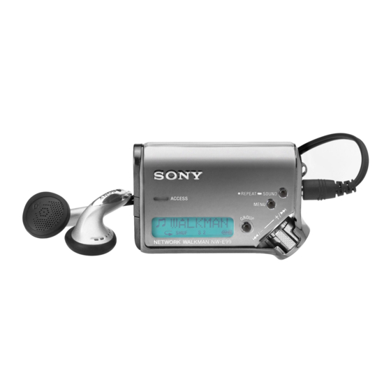
PORTABLE IC AUDIO PLAYER
NW-E99
US Model
Canadian Model
AEP Model
Tourist Model
Supplied accessories
Headphones (1)
Dedicated USB cable (1)
Carrying pouch (1)
Neck strap (1)
Extension headphone cord (1)
CD-ROM for the SonicStage software (1)
Operating Instructions (1)
SonicStage Operating Instructions (1)
CD-ROM for the Operating Instructions and
SonicStage Operating Instructions (1)
Design and specifications are subject to
change without notice.
US and foreign patents licensed from Dolby
Laboratories.
E Model
Advertisement
Table of Contents

Related Manuals for Sony NW-E99


Summary of Contents for Sony NW-E99
- Page 1 (w/h/d, projecting parts not included) 20 to 20,000 Hz (single signal measurement) Mass Output Approx. 40 g (2 oz) (battery not included) Headphone: Stereo mini-jack PORTABLE IC AUDIO PLAYER Sony Corporation 9-879-316-06 Connect Company 2005I16-1 Published by Sony Engineering Corporation © 2005.09...
-
Page 2: Table Of Contents
NW-E99 TABLE OF CONTENTS GENERAL Microsoft, Windows and Windows Media are trademarks or ..............3 registered trademarks of Microsoft Corporation in the United States and/or other countries. TEST MODE ............... 5 US and foreign patents licensed from Dolby Laboratories. All other trademarks and registered trademarks are trademarks or DISASSEMBLY registered trademarks of their respective holders. -
Page 3: General
NW-E99 SECTION 1 GENERAL This section is extracted from instruction manual. Locating controls Front side Rear side 1 Strap hole for attaching the strap 7 Headphone jack 2 REPEAT/SOUND button 8 Nx button 3 MENU button 9 Shuttle switch You can switch to the Time display by pressing the MENU button for a while. - Page 4 NW-E99 Adjusting the As you did in step 3, adjust the settings for “month” and “date.” current time After rotating the Shuttle switch to adjust the setting (DATE- “date” setting and pressing the Nx button to confirm, the display switches to the time TIME) setting screen.
-
Page 5: Test Mode
SECTION 2 TEST MODE STANDING PROCEDURE Procedure 1: Set a dry battery into NW-E99, and keep the battery lid open. Procedure 2: In HOLD state, while pushing Nx and [GROUP] button, turn power on by closing the battery lid of NW-E99. -
Page 6: Disassembly
NW-E99 SECTION 3 DISASSEMBLY Note: Disassemble the unit in the order as shown below. 3-1. CASE,CHASSIS (FRONT) ASSY (Page 6) 3-2. DISPLAY BOARD ASSY (Page 7) 3-3. MAIN BOARD ASSY (Page 7) Note: Follow the disassembly procedure in the numerical order given. -
Page 7: Display Board Assy
NW-E99 3-2. DISPLAY BOARD ASSY 4 DISPLAY board assy 3 cover section 2 tapping screw (1.7) lid (usb) (sub assy) 3-3. MAIN BOARD ASSY 1 tapping screw (B1.7 × 7) ornament assy 4 MAIN board assy 3 chassis (rear) 2 two claws... -
Page 8: Diagrams
NW-E99 SECTION 4 DIAGRAMS Note on Schematic Diagram: Note on Printed Wiring Board • All capacitors are in µF unless otherwise noted. (p: pF) 50 WV or • X : parts extracted from the component side. • Y : parts extracted from the conductor side. -
Page 9: Block Diagram
NW-E99 4-1. BLOCK DIAGRAM NAND FLASH RAM Q460 NOR FLASH SRAM IC461 IC450 2.8V R/B1 DQ0 - 15 A1 - 19 I/O1 - 8 29 - 36, 38 - 45 1 - 8, 16 - 25, 48 13 14 15 26 28... -
Page 10: Display Board (Side A)
NW-E99 Ver. 1.1 :Uses unleaded solder. 4-2. PRINTED WIRING BOARD – DISPLAY BOARD (SIDE A) – DISPLAY BOARD (SIDE A) L I Q U I D C R Y S TA L D I S P L AY R852 MAIN... -
Page 11: Display Board (Side B)
NW-E99 Ver. 1.1 :Uses unleaded solder. 4-3. PRINTED WIRING BOARD – DISPLAY BOARD (SIDE B) – DISPLAY BOARD (SIDE B) REPEAT SOUND IC801 ACCESS MENU > GROUP (21) 1-862-329- EL ELEMENT NW-E99... -
Page 12: Schematic Diagram - Display Board
NW-E99 Ver. 1.1 • See page 17 for IC Block Diagram. 4-4. SCHEMATIC DIAGRAM – DISPLAY BOARD – S701 CN402 S705 C702 S708 S704 100p R701 R704 R700 TP701 ADK2 TP705 GROUP TP804 VDD_EL L801 LCD_A0 R851 100k TP850 LCDRST... -
Page 13: Printed Wiring Board - Main Board (Side A)
NW-E99 :Uses unleaded solder. IC400 (microcomputer) and IC450 (nor flash sram) on MAIN 4-5. PRINTED WIRING BOARD – MAIN BOARD (SIDE A) – board cannot be replaced individually. Replace it with MAIN board assembly for service. MAIN BOARD (SIDE A) -
Page 14: Printed Wiring Board - Main Board (Side B)
NW-E99 :Uses unleaded solder. 4-6. PRINTED WIRING BOARD – MAIN BOARD (SIDE B) – MAIN BOARD (SIDE B) S702 S703 VOLUME VOLUME S703 HOLD IC501 IC504 S707 IC502 IC505 IC510 IC700 IC500 (31) 1-862-328- DISPLAY BOARD CN402 (Page 10) DRY BATTERY SIZE "AAA"... -
Page 15: Schematic Diagram - Main Board (1/2)
NW-E99 Ver. 1.5 • See page 17 for IC Block Diagram. • See page 8 for Waveform. IC400 (microcomputer) on MAIN board cannot be replaced 4-7. SCHEMATIC DIAGRAM – MAIN BOARD (1/2) – individually. Replace it with MAIN board assembly for service. -
Page 16: Schematic Diagram - Main Board (2/2)
NW-E99 • See page 17 for IC Block Diagram. IC450 (nor flash sram) on MAIN board cannot be replaced 4-8. SCHEMATIC DIAGRAM – MAIN BOARD (2/2) – individually. Replace it with MAIN board assembly for service. R450 C450 CN400 TP504... - Page 17 NW-E99 • IC Block Diagrams – MAIN Board – IC301 NJM2776RB2 (TE2) V + 2 OUT1 OUT2 8 IN2 STANDBY STANDBY BIAS V + 1 VREF IC700 RS5C348A-E2-FB 32 kHz 32KOUT ALARM W REGISTER OUTPUT COMPARATOR (WEEK, MIN, HOUR) CONTROL...
-
Page 18: Exploded Views
NW-E99 Ver. 1.4 SECTION 5 EXPLODED VIEWS NOTE: • -XX and -X mean standardized parts, so they • The mechanical parts with no reference may have some difference from the original number in the exploded views are not supplied. one.A •... -
Page 19: Main Board Section
NW-E99 Ver. 1.5 5-2. MAIN BOARD SECTION Ref. No. Part No. Description Remark Ref. No. Part No. Description Remark 3-318-203-81 SCREW (B1.7X7), TAPPING 2-342-341-31 CHASSIS (REAR) 3-266-604-21 ORNAMENT X-2102-785-1 MAIN BOARD, COMPLETE 3-266-584-11 BUTTON (PLAY) 3-266-606-01 SHAFT (PLAY) 3-266-608-01 SHEET (COVER), ADHESIVE... -
Page 20: Electrical Parts List
NW-E99 Ver. 1.5 SECTION 6 DISPLAY MAIN ELECTRICAL PARTS LIST NOTE: • Due to standardization, replacements in the • Items marked “*” are not stocked since they • CAPACITORS uF: µF parts list may be different from the parts are seldom required for routine service. - Page 21 NW-E99 Ver. 1.5 MAIN Ref. No. Part No. Description Remark Ref. No. Part No. Description Remark C204 1-115-467-11 CERAMIC CHIP 0.22uF < CONNECTOR > C300 1-104-851-11 TANTAL. CHIP 10uF CN400 1-818-513-11 CONNECTOR (SQUARE TYPE) (USB) 5P ( C301 1-125-777-11 CERAMIC CHIP 0.1uF...
- Page 22 NW-E99 MAIN Ref. No. Part No. Description Remark Ref. No. Part No. Description Remark R103 1-218-973-11 RES-CHIP 1/16W R522 1-218-973-11 RES-CHIP 1/16W R200 1-218-961-11 RES-CHIP 4.7K 1/16W R523 1-218-985-11 RES-CHIP 470K 1/16W R524 1-218-989-11 RES-CHIP 1/16W R201 1-208-635-11 METAL CHIP 0.5%...
- Page 23 NW-E99 Ver. 1.5 Ref. No. Part No. Description Remark ACCESSORIES ************ 1-823-519-31 CORD, CONNECTION (USB CABLE) 1-824-856-13 CORD, CONNECTION (EXTENTION HEADPHONE CORD) 2-187-170-01 POUCH, CARRYING 2-581-015-11 MANUAL, INSTRUCTION (ENGLISH) (US, CND, HK, JE) 2-581-015-21 MANUAL, INSTRUCTION (SIMPLIFIED CHINESE) (JE) 2-581-015-31 MANUAL, INSTRUCTION...
- Page 24 NW-E99 REVISION HISTORY Clicking the version allows you to jump to the revised page. Also, clicking the version at the upper right on the revised page allows you to jump to the next revised page. Ver. Date Description of Revision 2004.11...