GE Evolution Series E9000 User Manual
Motor control centers
Hide thumbs
Also See for Evolution Series E9000:

Related Manuals for GE Evolution Series E9000


Summary of Contents for GE Evolution Series E9000
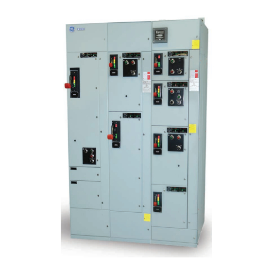
- Page 1 GE Energy Connections Evolution Series E9000 Motor Control Centers User Manual DEH-40472 Rev. 08...
-
Page 2: Table Of Contents
Publications Available from GE ........ -
Page 3: Warnings, Cautions & Notes
Features may be described herein that are not present in all hardware and software systems. GE Energy Connections assumes no obligation of notice to holders of this document with respect to changes subsequently made. -
Page 4: Introduction
Each shipping split includes a continuous non-removable main horizontal bus. Main bus splice bars are provided Refer to the GE requisition number found on the front within each shipping split for eld connecting main of the equipment when calling for assistance. -
Page 5: General Description - Arc Resistant
Evolution Series E9000 User Manual General Description – Arc Resistant The Arc Resistant sections are built with increased structural capacity. The main enhancements are thicker gage of steel, latches, hinges, and metallic PD brackets. In addition, there are two versions available with and without a plenum. -
Page 6: Bus Splicing
Evolution Series E9000 User Manual Bus Splicing Table 1. Torque values for various bolt sizes and joint types Main, neutral and ground bus splice bars (with all Copper Joints Aluminum Joints Bolt Size lb-ft lb-ft associatedhardware) are furnished, as necessary, to 5/16-18 5–9... -
Page 7: Receiving, Handling & Storage
Evolution Series E9000 User Manual Chapter 2 – Receiving, Handling & Storage Receiving Before leaving the factory, the motor control center is given a nal mechanical and electrical inspection and is packed in accordance with the best practices for electrical equipment. -
Page 8: Installation
Evolution Series E9000 User Manual Chapter 3 – Installation Before any installation work is begun, consult all drawings furnished by the GE as well as all applicable contract drawings for the particular installation. Pay particular attention to the location of units in the motor control center and their relations to existing or planned conduits and busways. - Page 9 Evolution Series E9000 User Manual Indoor Enclosures Elevation and Mounting 30" Deep Sections 600A to 1200A Main Bus Top Conduit Entry 30" Deep Section...
-
Page 10: Installation Of Bottom Entry Conduits
Exceptions to this available space rule are indicated on drawings furnished by GE for speci c installations. Center the conduit beneath the section vertical wireway to facilitate direct cable entry. Note: Bottom rear entrance should only be used with full Figure 6C (Arc Resistant). -
Page 11: Installation Of Flooring
13-inch deep section, 6-inch cover by GE for the speci c equipment. Locate one in the center front and one in the center back. Anchor bolts should be 1/2"... -
Page 12: Positioning And Joining Sections
Evolution Series E9000 User Manual Positioning and Joining Sections For Type 12 and Arc Resistant enclosure, see Figure 10A for proper gasket in between the section splits. For If groups of sections are to be joined together in a nal additional gasket material order part number 245A1888P5. -
Page 13: Installation Of Top Entry Conduits
Evolution Series E9000 User Manual plenum the conduit can be assembled on top of the plenum. GE o ers an additional pull box for higher conduit space requirement. The Pull box can be assembled on top of the incoming section. -
Page 14: Exhaust Fan Installation
Main Incoming Power Cables the covers must be removed and discarded. The exhaust Refer to the motor control center drawings provided by GE fan assembly can then be installed as shown in Figure 15A. for the location of the main disconnect or incoming line terminals and the direction (top or bottom) of cable entry. -
Page 15: Individual Unit Wiring
Evolution Series E9000 User Manual based on horizontal bus bracing. However, cables Individual Unit Wiring should always be secured at the rst support inside the Open the vertical wireway door(s) and the top and/or enclosure and at the support nearest to the incoming bottom horizontal wireway hinged covers. -
Page 16: Wiring Nema Type B Motor Control Centers
(Refer to 2. Pull load cables near the unit to be wired. Measure the drawings provided by GE for the locations of master (allowing for cable bends), cut and strip the cables, terminal boards.) Figure 19 and Figure 20 show typical and feed them carefully through barrier knockout Type C terminal board arrangements. -
Page 17: Wiring Between Sections
Evolution Series E9000 User Manual Wiring Between Sections Terminal Blocks Figure 21 shows the dimensions of side cutouts in each The new style terminal blocks are mounted on a metal vertical section for wiring between sections. Cross-wiring rail located at the bottom of the unit, as shown in can be accomplished at both the top and bottom of Figure 22. - Page 18 Evolution Series E9000 User Manual Use the following procedure to install a motor control center unit: Attach the door hinges to the left side of the section, line up the door with the hinges, then insert the hinge pins to secure the door. (For Type 12 enclosures, mount the gasket on hinge side.
-
Page 19: Removal Of Draw-Out Motor Control Center Units
Evolution Series E9000 User Manual Removal of Draw-Out Motor Control Center Units Operating Handles, Door Interlocks and Padlocking Provisions All Evolution motor control center units are furnished Some units may still have control power applied with disconnect operating handles that are integral from an external source after the unit disconnect has been switched to the OFF position. -
Page 20: Operating Handle
Evolution Series E9000 User Manual CAUTION: The friction of Type 12 gasketing can prevent the breaker disconnect operating handle from returning to the full ON position. Prior to servicing, con rm breaker disconnect is in the OFF position. Operating Handle The operating handle must be moved out of the way to access the breaker disconnect. -
Page 21: Pilot Bracket And Door
Evolution Series E9000 User Manual Pilot Bracket and Door NEMA 3R Outdoor Enclosure Installation The pilot device door can be removed by lifting straight o per Figure 33. Also, the metal bracket can be removed by loosening mounting screws and removing bracket. - Page 22 Evolution Series E9000 User Manual...
-
Page 23: Operation
16. For AFM Units, ensure that all visual indicators are a. If trip settings must be changed, use the GE rating showing “RED” to indicate “ENGAGED” stab position plug extractor tool (catalog number TRTOOL) to and “OPEN”... -
Page 24: Door Closing Procedure
Evolution Series E9000 User Manual 3. Verify (with an insulation-resistance tester) that all Door Closing Procedure of Pilot Device Bracket, main incoming feeders to the motor control center Extension Bubble Door for Some GP/FP Drives are adequately insulated. E9000 MCC units 4. - Page 25 Evolution Series E9000 User Manual Figure 37. Partially close the door as shown Locking Bracket Extension Bubble Door Door Cut Out Gasket Figure 38. Adjust the pilot device bracket and extension bubble lip so it enters in between the keeper bracket and inside of the door 1/4 Turn Latch Figure 39.
-
Page 26: Maintenance
“On” allowing the secondary control power to be utilized. only results in lost tip material and reduces starter The key switch should be “O ” during normal operation life. See GE publication GET-6915A for questionable of the MCC. contact appearance. -
Page 27: Suggested Maintenance Tools
• GE Spectra circuit breaker rating plug removal tool, exceed the vertical bus rating label on each section. catalog number TRTOOL (see Figure 41). • GE pilot light and push button removal tool, catalog number GEN-1684A (see Figure 42). Replacing or Adding Breaker Accessories to •... -
Page 28: Replace A Compact Starter (1/2 X)
Evolution Series E9000 User Manual Replacing a Compact Starter (1/2X) Arc Flash Mitigation Units DEI-007 – Remote Racking System Instructions Use the following procedure to replace the starter. DEI-009 – AFM Retro t Assembly Instructions 1. Turn the power o . -
Page 29: Renewal Parts
• Push buttons: start-stop, forward, reverse, up, down by installation needs. • Transfer switch: H-O-A Your GE account manager will be glad to assist you in • Pilot lights: quantity, color and type preparing a recommended parts list for your installation. -
Page 30: Overload Heaters
Evolution Series E9000 User Manual Chapter 6 –Overload Heaters Heaters for Ther-Mag Circuit Breaker Controllers Size 2 (Standard and Ambient Comp.) Motor Full- Heater Motor Full- Heater For continuous-rated motors with a service factor of Load Amps Number Load Amps Number 1.15 to 1.25, select the appropriate heaters for the... -
Page 31: Heaters For Mag-Break Controllers
Evolution Series E9000 User Manual Size 5 (Standard and Ambient Comp.) Circuit breaker tripping may be an indication that a fault current has been interrupted. To provide Motor Full- Heater Motor Full- Heater continued protection against re or shock hazard,... - Page 32 Evolution Series E9000 User Manual Size 0 and 1 (Ambient Comp.) Size 2 (Standard) Motor Full- Heater TEC & Mag-Break Motor Full- Heater TEC & Mag-Break Trip Setting Load Amps Number TECL Trip Setting Load Amps Number TECL 3-Ph, 3 Heater...
- Page 33 Evolution Series E9000 User Manual Size 3 (Standard and Ambient Comp.) cont. Size 0 and 1 (Standard) Mag-Break Motor Full- Heater TEC & Mag-Break Motor Full- Heater Load Amps Number TECL Trip Setting Trip Setting Load Amps Number Rating 3-Ph, 3 Heater...
- Page 34 Evolution Series E9000 User Manual Size 0 and 1 (Ambient Comp.) Size 2 (Standard) Mag-Break Mag-Break Motor Full- Heater Motor Full- Heater Trip Setting Trip Setting Load Amps Number Rating Load Amps Number Rating 3-Ph, 3 Heater CR123 Plug Rec.
- Page 35 Evolution Series E9000 User Manual Size 4 (Standard) Size 4 (Standard) Mag-Break Mag-Break Motor Full- Heater Motor Full- Heater Trip Setting Trip Setting Load Amps Number Rating Load Amps Number Rating 3-Ph, 3 Heater CR123 Plug Rec. Max. 3-Ph, 3 Heater...
-
Page 36: Heaters For Fused Controllers
Evolution Series E9000 User Manual Heaters for Fused Controllers Size 5 – 300:15 CT (Standard and Ambient Comp.) Instantaneous Motor Full- Heater For continuous-rated motors with a service factor of Trip Setting Load Amps Number Rating 1.15 to 1.25, select the appropriate heaters for the... - Page 37 Evolution Series E9000 User Manual Size 5 – 300:15 CT (Standard and Ambient Comp.) Size 2 (Standard and Ambient Comp.) Motor Full- Heater Maximum Motor Full- Heater Maximum Load Amps Number Fuse Load Amps Number Fuse 3-Ph, 3 Heater CR123...
- Page 38 Evolution Series E9000 User Manual Size 3 (Ambient Comp.) Size 5 – 300:15CT (Standard and Ambient Comp.) Motor Full- Heater Maximum Motor Full- Heater Maximum Load Amps Number Fuse Load Amps Number Fuse 3-Ph, 3 Heater CR123 Rating 3-Ph, 3 Heater...
-
Page 39: Heaters For Nema Size 6 And 7 Fused Controllers
Evolution Series E9000 User Manual Heaters for NEMA Size 6 and 7 Fused Controllers Electronic Overload for Circuit Breaker and Fused Controllers For continuous-rated motors with a service factor of 1.15 to 1.25, select the appropriate heaters for the The tripping current is 120% of the dial setting. For motor full-load current. - Page 40 Evolution Series E9000 User Manual Catalog numbers of electronic overloads for various sizes of NEMA IEC Style Overload Relays starters and current ranges C2000 Contactor CLNCJ Type RT Overload Relay for 1/2X Starter NEMA FLA Range Catalog Max. Fuse Current...
- Page 41 Evolution Series E9000 User Manual AF-600 FP / AF-650 GP Drives E9000 Mount direct to contactor Panel mount use with RTXP base adapter Cat. No. Lug/ Wire Torque Contactor FLA Range Size (in-lbs) Cat. No. Lug/ Wire Torque Class 10 Class 20...
- Page 42 Evolution Series E9000 User Manual Notes...
- Page 43 Evolution Series E9000 User Manual Notes...
- Page 44 *Registered trademark of the General Electric Company . The GE brand, and logo are trademarks of the General Electric Company . © 2017 General Electric Company . Information provided is subject to change without notice . All values are design or typical values when measured under laboratory conditions .