Table of Contents
Advertisement
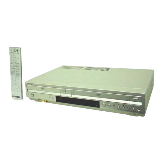
SLV-D973P E/D983P D/D983P GI
SERVICE MANUAL
System
Laser
Semiconductor laser
Signal format system
PAL/(NTSC)
Channel coverage
SLV-D973P E/D983P D:
PAL (B/G):
VHF E2 to E12
VHF Italian channel A to H
UHF E21 to E69
CATV S01 to S05, S1 to S20
HYPER S21 to S41
SLV-D983P GI:
PAL (I):
VHF IA to IJ, SA10 to SA13
UHF E21 to E69
CATV S01 to S05, S1 to S20
HYPER S21 to S41
PAL
Refer to the SERVICE MANUAL of VHS MECHANI-
CAL ADJUSTMENT MANUAL VII for MECHANICAL
ADJUSTMENTS. (9-921-790-11)
SPECIFICATIONS
Aerial out
75-ohm asymmetrical aerial socket
Tape speed
SP: PAL
23.39 mm/s
(recording/playback)
NTSC
33.35 mm/s
(playback only)
LP: PAL
11.70 mm/s
(recording/playback)
NTSC
16.67 mm/s
(playback only)
EP: NTSC
11.12 mm/s
(playback only)
Maximum recording/playback time
10 hrs. in LP mode (with E300 tape)
Rewind time
Approx. 2 min. 30 sec. (with E180 tape)
VIDEO CASSETTE RECORDER
RMT-V503C
AEP Model
SLV-D973P E/D983P D
UK Model
SLV-D983P GI
DX-13A MECHANISM
Inputs and outputs
LINE-1 (EURO AV)
21-pin
Video input: pin 20
Audio input: pins 2 and 6
Video output: pin 19
Audio output: pins 1 and 3
LINE-2 IN t / o L/R
VIDEO IN, phono jack (1)
Input signal: 1 Vp-p, 75 ohms, unbalanced,
sync negative
AUDIO IN, phono jacks (2)
Input level: 327 mVrms
Input impedance: more than 47 kilohms
LINE-3
21-pin
Video input: pin 20
Audio input: pins 2 and 6
— Continued on next page —
DVD PLAYER/
Advertisement
Table of Contents

Related Manuals for Sony SLV-D983P


Summary of Contents for Sony SLV-D983P
-
Page 1: Dvd Player
SLV-D973P E/D983P D/D983P GI RMT-V503C SERVICE MANUAL AEP Model SLV-D973P E/D983P D UK Model SLV-D983P GI DX-13A MECHANISM Refer to the SERVICE MANUAL of VHS MECHANI- CAL ADJUSTMENT MANUAL VII for MECHANICAL ADJUSTMENTS. (9-921-790-11) SPECIFICATIONS System Aerial out Inputs and outputs... - Page 2 Timer section Supplied accessories VIDEO OUT, phono jack (1) Clock Remote commander (1) Output signal: 1 Vp-p, 75 ohms, unbal- Quartz locked R6 (size AA) batteries (2) anced, sync negative Timer indication Aerial cable (1) AUDIO OUT, phono jacks (2) 24-hour cycle Standard output: 327 mVrms Timer setting...
- Page 3 IC pins, etc. OPERATION. REPLACE THESE COMPONENTS WITH • Usable with ordinary solder SONY PARTS WHOSE PART NUMBERS APPEAR AS It is best to use only unleaded solder but unleaded solder may SHOWN IN THIS MANUAL OR IN SUPPLEMENTS PUB- also be added to ordinary solder.
-
Page 4: Table Of Contents
TABLE OF CONTENTS Precautions PCB Diagrams Safety Precautions ............... 5 VCR Main ............... 4-3 Servicing Precautions ............7 DVD Main ............... 4-7 ESD Precautions ..............8 Function Timer .............. 4-11 Handling the Optical Pick-up ..........9 Schematic Diagrams Pick-up Disassembly and Reassembly ......10 S.M.P.S. -
Page 5: Precautions Safety Precautions
PRECAUTIONS 1 SAFETY PRECAUTIONS 1) Before returning an instrument to the customer, always make a (4) Insulation Resistance Test Cold Check-(1) Unplug the power safety check of the entire instrument, including, but not limited supply cord and connect a jumper wire between the two prongs to, the following items: of the plug. - Page 6 6) Product Safety Notice-Some electrical and mechanical parts have special safety-related characteristics which are often not evident from visual inspection, nor can the protection they give necessarily be obtained by replacing them with components rated for higher voltage, wattage, etc. Parts that have special safety characteristics are identified by shading, an ( ) or a ( ) on...
-
Page 7: Servicing Precautions
2 SERVICING PRECAUTIONS CAUTION: Before servicing units covered by this service manual and its supplements, read and follow the Safety Precautions section of this manual. Note: If unforseen circumstances create conflict between the following servicing precautions and any of the safety precautions, always follow the safety precautions. -
Page 8: Esd Precautions
3 ESD PRECAUSIONS Electrostatically Sensitive Devices (ESD) Some semiconductor (solid state) devices can be damaged easily by static electricity. Such components commonly are called Electrostatically Sensitive Devices (ESD). Examples of typical ESD devices are integrated circuits and some field-effect transistors and semiconductor chip components. -
Page 9: Handling The Optical Pick-Up
4 HANDLING THE OPTICAL PICK-UP The laser diode in the optical pick up may suffer electrostatic breakdown because of potential static electricity from clothing and your body. The following method is recommended. (1) Place a conductive sheet on the work bench (The black sheet used for wrapping repair parts.) (2) Place the set on the conductive sheet so that the chassis is grounded to the sheet. -
Page 10: Pick-Up Disassembly And Reassembly
5 PICK-UP DISASSEMBLY AND REASSEMBLY 5-1 Disassembly 5-2 Assembly 1) Replace the Pick-up. 1) Remove the power cord. 2) Remove the soldering 2 points on Pick-up. 2) Disassemble the Deck-Assy. 3) Reassemble the Deck-Assy. 3) Make solder land 2 points short on Pick-up. (See Fig. -
Page 11: General
SLV-D973P E/D983P D/D983P GI 1. GENERAL This section is extracted from instruction manual. (2-671-548-11) Region code Notes about DVD+RWs/ About this manual This player can play the DVD+Rs, DVD-RWs/DVD-Rs or following discs Your player has a region code printed on the CD-Rs/CD-RWs •... - Page 12 Reattach the cover after inserting the battery. The remote commander is preprogrammed to control non-Sony TVs. If your TV is listed in the following table, set the appropriate manufacturer’s code number. Set TV / DVD·VIDEO switch at the top of the remote commander to TV.
- Page 13 B Use this hookup if your TV has a Scart (EURO-AV) connector Connecting to a satellite or digital tuner Connect a satellite or digital tuner to this DVD-VCR using the LINE-3 jack. Scart cable (not supplied) Scart (EURO-AV) LINE-1 LINE-3 Mains lead (EURO AV) to mains...
- Page 14 Step 5 : Selecting a language Step 6 : Setting the clock You can change the on-screen display You must set the clock on the DVD-VCR to language. use the timer features properly. SET UP Before you start… The Auto Clock Set function works only if a SET UP •...
- Page 15 If the picture is not clear Press V/v to select the row which you want to MANUAL TUNING If the picture is not clear, you may use the Manual Fine Tuning (MFT) function. preset, then press b. After step 5, press V/v to select “MFT.” Press B/b to get a clear picture. Then –...
-
Page 16: Advanced Hookups
Advanced Hookups Press V/v to select the row which you want to change or enter MANUAL TUNING S-Video/Component Video hookup the station name, then press b. – To display other pages for programme positions 6 to 80, press NAME – – – – V/v repeatedly. -
Page 17: Basic Operations
Basic Operations A Connecting to audio L/R jacks Playing discs This connection uses a stereo amplifier’s (receiver’s) two front speakers for sound. You can enjoy the surround function that creates virtual speakers from two stereo speakers. Select from “Surround1”, “Surround2” or “Surround3” of the surround Depending on the disc, some operations may effects (page 77). - Page 18 To playback quickly or slowly with sound (DVD only) Guide to the on-screen display You can listen to dialog or sound while playing the current scene quickly or slowly. To playback quickly, press M during playback. To playback slowly, press X, then press during playback.
-
Page 19: Playing A Tape
Additional operations Playing a tape Press Before you start... Stop play • Turn on the DVD-VCR and your TV. Pause play • Set the TV to video input so that the signal SELECT VIDEO If you pause the VCR for more than 5 minutes, the VCR will from the player appears on the TV screen. - Page 20 To check the remaining time • To record a normal channel, press PROG +/– until the programme • PROG/ Press DISPLAY three times. With the display on, press DISPLAY again to check the TRACKING position number you want appears in the display window. remaining time.
- Page 21 Press V/v to select “VideoPlus,” then press If you want to change the date, tape speed and VideoPlus PR DATE START STOP SPEED PDC ENTER. the PDC setting: 19 : 00 20 : 00 ENTER Code – – – – – – – – – ENTER –...
- Page 22 To stop recording Press V/v to select “Standard,” then press To stop the DVD-VCR while recording, press SELECT VIDEO and then press x. PR DATE START STOP SPEED PDC ENTER. ENTER The timer programming menu appears. Daily/weekly recording In step 4, press v to select the recording pattern. Each time you press v, the indication changes as shown below.
-
Page 23: Dvd Settings And Adjustments
DVD Settings and Adjustments Press B/b to select an item. Audio Setup ENTER “Audio Setup” allows you to set the sound SET UP according to the playback and connection conditions. Press SET UP to exit the menu. SET UP Before you start... •... -
Page 24: Setting The Display Or Sound Track Language
• DVD Component Out Press B/b to select an item. Selects whether or not to output DVD Component Out signals from the DVD Component Out jack on the rear panel of the player. ENTER The default setting is indicated in bold print. Select this to output DVD Component Out signals. - Page 25 Press V/v to select the language setup item from the displayed list: Parental Control (limiting playback by children) “DVD Menu,” “Audio,” or “Subtitle.” ENTER Then press ENTER. Playback of some DVD VIDEOs can be Press V/v to select the desired language, then press ENTER. limited according to a predetermined level •...
-
Page 26: Dvd Additional Operations
DVD Additional Operations Using the DVD’s menu Zooming into a scene A DVD is divided into long sections of a You can zoom into a scene during playback ZOOM picture or a music feature called “titles.” or still mode. When you play a DVD VIDEO which To zoom into a JPEG image, see “Playing contains several titles, you can select the title JPEG image files”... -
Page 27: Various Play Mode Functions
Press V/v repeatedly to select “On.” Various play mode functions (Programme ENTER play, Shuffle play, Repeat play) To turn off the subtitles Before you start... Select “Off” in step 4. • Set TV / DVD·VIDEO switch to Note DVD·VIDEO on the remote (page 10). •... -
Page 28: Changing The Sound
Press REPEAT or B/b to select the item to be repeated. Changing the sound When playing a DVD • Chapter: repeats the current chapter. When playing a DVD recorded in multiple • Title: repeats the current title on a disc. audio formats (PCM, Dolby Digital, MPEG or DTS), you can change the audio format. -
Page 29: Playing An Mp3 Audio Track
To cancel the setting Playing an MP3 audio track Select “Off” in step 2. Notes You can play back DATA CDs (CD-ROMs/ • When the playing signal does not contain a signal for the rear speakers, the surround effects CD-Rs/CD-RWs) or DATA DVDs (DVD- will be difficult to hear. -
Page 30: Playing Jpeg Image Files
Notes Notes • Up to 20 tracks can be programmed at one time. • If you put the extension “.MP3” to data not in MP3 format, the player cannot recognize the data properly and will generate a loud noise which could damage your speaker system. •... - Page 31 Note Press V/v to select “JPEG,” then press • You cannot use ZOOM on the remote in JPEG image files on DATA CD/DATA DVD. Album Photo: ENTER. ENTER To enjoy the Slide show The “Album” display will appears. Press V/v/B/b to select an image in the “Album” If you do not press ENTER after selecting a Interval display, then press ENTER.
-
Page 32: Vcr Additional Operations
VCR Additional Operations Press ENTER. Quick Timer Recording ENTER After you have started recording, you can have the VCR stop recording automatically after a specified duration. Follow the instructions in the menu for interactive operations. Refer to the instructions supplied with the disc, as the operating procedure may differ depending on the VIDEO CD. - Page 33 Selecting the sound during Hi-Fi playback Searching using index function Press AUDIO to select the sound you want. The VCR automatically marks the tape with To listen to On-screen display Display window an index signal at the point where each recording begins.
-
Page 34: Changing Menu Options
Press V/v to select “User Set,” then press USER SET Changing menu options ENTER. [ Auto ] Colour System ENTER [ On ] NICAM Smart Trilogic [ On ] You can change the tape length, auto play VideoPlus Extend [ Off ] and auto repeat settings for the VCR. -
Page 35: Additional Information
Example C Operation (when recording on this VCR) Your VCR (Recorder) Before you start editing • Turn on your TV and set it to the video channel. • When you connect another VCR to the LINE-3 or LINE-2 connector, press INPUT SELECT to display “L3”... - Page 36 Symptom Remedy There is no picture/picture noise • Re-connect the connecting cord securely. If you have any questions or problems not covered below, please consult your nearest Sony appears. • The connecting cords are damaged. service facility. • Check the connection to your TV (page 13) and switch...
-
Page 37: Index To Parts And Controls
Symptom Remedy Glossary No TV programme appears on the • Make sure the TV is set to the video channel. If you are TV screen. using a monitor, set it to video input. • Select the correct source with the INPUT SELECT Chapter (page 35) DVD (page 6) button. - Page 38 A Z (open/close) button (31) (33) Display window Remote commander for DVD B TV / DVD·VIDEO switch (10) C SELECT DVD button (10) D Number buttons* (11) (64) E CLEAR button (25) (72) F SURROUND button (77) G SET UP button (18) H SUBTITLE button (69) I AUDIO button* (75) SKIP button (32)
- Page 39 Index Numerics 16:9 58 Index scan 96 Recording 41 4:3 Letter Box 58 Index search 96 daily/weekly 51 4:3 Pan Scan 58 Instant Advance 33 quick timer recording 91 Instant Replay 33 saving 43 using the VIDEO Plus+ Instant Skip 39 Adjusting system 45 picture 97...
- Page 40 MEMO 1-30E...
-
Page 41: Disassembly And Reassembly
SLV-D973P E/D983P D/D983P GI 2. DISASSEMBLY AND REASSEMBLY 2-1 CABINET AND PCB 2-1-1 Cabinet Top Removal 2-1-3 Ass’y Front Panel Removal 2 Lift up the Cabinet Top in the direction of arrow 1 RELEASE 4 HOOKS 1 REMOVE 3 SCREWS (Top view) Fig. -
Page 42: Chassis Removal
2-1-5 Chassis Removal 2 REMOVE 4 SCREWS 1 REMOVE 2 SCREWS VCR DECK 3 REMOVE 3 SCREWS 5 REMOVE 3 SCREWS DVD DECK 4 REMOVE 2 SCREWS VCR MAIN PCB DVD MAIN PCB FUNCTION TIMER PCB 6 REMOVE 1 SCREWS Fig. -
Page 43: Circuit Board Locations
2-2 CIRCUIT BOARD LOCATIONS DVD MAIN PCB VHS MAIN PCB FUNCTION TIMER PCB Fig. 2-7 Circuit Board Locations... -
Page 44: Vcr Deck Parts Locations
2-3 VCR DECK PARTS LOCATIONS 2-3-1 Top View Fig. 2-8 Top parts Location-1 1 GEAR FL CAM 2 ASS’Y MOTOR LOADING 3 ASS’Y LEVER ARM 4 ASS’Y HOLDER CASSETTE 5 LEVER FL DOOR 6 SLIDER FL DRIVE... - Page 45 qa 0 qs Fig. 2-9 Top Parts Location-2 1 FE HEAD 8 DISK S REEL 2 ASS’Y CYLINDER 9 ASS’Y LEVER S BRAKE 3 ASS’Y ACE HEAD 0 GEAR IDLE 4 ASS’Y LEVER UNIT PINCH qa LEVER IDLE 5 ASS’Y LEVER #9 GUIDE qs ASS’Y LEVER T BRAKE 6 ASS’Y LEVER TENSION qd DISK T REEL...
-
Page 46: Bottom View
2-3-2 Bottom View Fig. 2-10 Bottom Parts Location 1 GEAR JOINT 1 2 GEAR JOINT 2 3 BRAKET GEAR 4 ASS’Y MOTOR CAPSTAN 5 ASS’Y LEVER T LOAD 6 GEAR LOADING DRIVE 7 ASS’Y LEVER S LOAD 8 ASS’Y CLUTCH 9 BELT PULLEY 0 SLIDER CAM... -
Page 47: Vcr Deck
2-4 VCR DECK 2-4-1 Ass’y Holder Cassette Removal 2-4-2 Ass’y Lever Arm Removal 1) Pull the Ass’y Holder Cassette 1 to the eject position. 1) Push the hole “A” in the direction of arrow “B” use the pin.(about 2) Pull the Ass’y Holder Cassette 1 as grasping the Ass’y Holder Dia. -
Page 48: Lever Door Removal
2-4-3 Lever Door Removal 2-4-4 Slider FL Drive, Gear FL Cam Removal 1) Release the Hook 2 and Remove the Lever Door 1 in the 1) Pull the Slider FL Drive 1 to the front direction. direction of arrow “A”. 2) Remove the Slider FL Drive 1 in the direction of arrow. -
Page 49: Gear Worm Wheel Removal
2-4-5 Gear Worm Wheel Removal 2-4-6 Cable Flat Removal 1) Remove the Gear Worm wheel 1. 1) Remove the Drum connecting part of Cable Flat 1 from Connector Waffer 2, 3. 1 CABLE FLAT 2 CONNECTOR WAFER 3 CONNECTOR WAFER 1 GEAR WORM WHEEL Fig. -
Page 50: Ass'y Motor Loading Removal
2-4-7 Ass’y Motor Loading Removal 2-4-8 Bracket Gear, Gear Joint 2, 1 Removal 1) Remove the screw 1. 1) Remove the SCREW 1. 2) Remove the Ass’y Motor Loading 2. 2) Remove the Bracket Gear 2. 3) Remove the Gear Joint 2 3. 4) Remove the Gear Joint 1 4. -
Page 51: Gear Loading Drive, Slider Cam
2-4-9 Gear Loading Drive, Slider Cam, 2-4-10 Gear Loading Drive, Slider Cam, Ass’y Lever Load S, T Removal Ass’y Lever Load S, T Assembly 1) Remove the Belt Pulley. (Refer to Fig. 2-38) 1) When reinstalling, be sure to align dot of Ass’y Lever Load T 2) Remove the Gear Loading Drive 1 after releasing Hook [A] in 1 with dot of Ass’y Lever Load S 2 as shown in drawing, the direction arrow as shown in detail drawing. -
Page 52: Lever Pinch Drive, Lever Tension Drive Removal
2-4-11 Lever Pinch Drive, 2-4-12 Ass’y Lever Tension, Lever Tension Drive Removal Ass’y Band Brake Removal 1) Remove the Lever Pinch Drive 1, Lever Tension Drive 2. 1) Remove the Ass’y Lever Brake S (Refer to Fig 2-25). 2) Remove the Spring Tension Lever 1. 1 LEVER PINCH DRIVE 3) Rotate stopper of Main Base in the direction of arrow “A”. -
Page 53: Ass'y Lever Brake S, T Removal
2-4-13 Ass’y Lever Brake S, T Removal 2-4-14 Ass’y Gear Idle Removal 1) Push the Lever Idle 1 in the direction of arrow “A”, “B”. 1) Release the Hook [A] and the Hook [B], [C] in the direction of arrow as shown in Fig 2-25. 2) Lift the Lever Idle 1. -
Page 54: Disk S, T Reel Removal
2-4-15 Disk S, T Reel Removal 2-4-16 Ass’y Holder Clutch Removal 1) Lift the Disk S, T Reel 1, 2. 1) Remove the Washer Slit 1. 2) Lift the Ass’y Holder Clutch 2. 1 REEL S Note: When you reinstall Ass’y Holder Clutch. 1) Check the condition of spring as shown in detail A. -
Page 55: Ass'y Lever Up Down, Ass'y Gear Center Removal
2-4-17 Ass’y Lever Up Down, Ass’y Gear 2-4-18 Guide Cassette Door Removal Center Removal 1) Lift the Hook [A]. 2) Rotate the Guide Cassette Door 1 in the direction of arrow. 1) Remove the 2 hooks in the direction of arrow as shown Fig. 2- 29 and lift the Ass’y Lever Up Down 1. -
Page 56: Ass'y Lever Unit Pinch, Plate Joint
2-4-19 Ass’y Lever Unit Pinch, Plate Joint, 2-4-20 Ass’y Lever #9 Guide Removal Spring Pinch Drive Removal 1) Remove the Spring #9 Guide 1. 2) Lift the Ass’y Spring #9 Guide 2 in the direction of arrow “A”. 1) Lift the Ass’y Unit Pinch 1. 2) Remove the Plate Joint 2 from Lever Pinch Drive. -
Page 57: Fe Head Removal
2-4-21 FE Head Removal 2-4-22 Ass’y ACE Head Removal 1) Rotate the FE Head 1 in the direction of life up. 1) Pull out the FPC from connector of Ass’y ACE Head 2. 2) Remove the screw 1. 3) Lift the Ass’y ACE Head 2. 1 SCREW 1 FE HEAD 2 ASS'Y HEAD ACE... -
Page 58: Ass'y Slider S, T Removal
2-4-23 Ass’y Slider S, T Removal 2-4-24 Plate Ground Deck, Ass’y Cylinder Re- moval 1) Move the Ass’y Slider S, T 1, 2 to slot, and then lift it to remove. (Refer to arrow) 1) Remove the 3 Screws 1. 2) Lift the Plate Ground Deck 2. -
Page 59: Hook Capstan, Belt Pulley Removal
2-4-25 Hook Capstan, Belt Pulley Removal 2-4-26 Ass’y Motor Capstan Removal 1) Remove the Hook Capstan 1 after realeasing Hook in the 1) Remove the 3 Screws 1. direction arrow as shown in detail drawing. 2) Remove the Ass’y Motor Capstan 2. 2) Remove the Belt Pulley 2. -
Page 60: Ass'y Post #8 Guide Removal
2-4-27 Ass’y Post #8 Guide Removal 2-4-29 How to Eject the Cassette Tape (If the tape is stuck in the unit) 1) Rotate the Ass’y Post #8 Guide 1 in the direction of arrow to lift up. 1) Turn the Gear worm 1 clockwise with screw driver.(Refer to arrow) (Other method: Remove the Screw of Ass’y Motor Load, Separate the Ass’y Motor Load) -
Page 61: The Table Of Cleaning, Lubrication And Replacement Time About Principal Parts
2-5 THE TABLE OF CLEANING, LUBRICATION AND REPLACEMENT TIME ABOUT PRINCIPAL PARTS 1) The replacement time of parts is not life of parts. 2) The table 2-1 is that the VCR Set is in normal condition (normal temperature, normal humidity). The checking period may be changed owing to the condition of use, runtime and environmental conditions. -
Page 62: Dvd Deck
2-6 DVD DECK 2-6-1 Holder Chuck Removal 1) Push 4 Hooks 1 in the direction of arrow “A” and lift up the Holder Chuck 2. 2 HOLDER CHUCK 1 2 HOOKS "A" 1 2 HOOKS "A" Fig. 2-44 Holder Chuck Removal 2-22... -
Page 63: Tray Disc Removal
2-6-2 Tray Disc Removal 1) Insert a Screw Driver 1 into Emergency Hole 2 and push the Slider Housing 3 in the direction arrow “A”. 2) When the Tray Disc 4 comes out a little, pull it in the direction arrow “B” by hand. 3 SLIDER HOUSING 4 TRAY DISC "B"... -
Page 64: Ass'y P/U Deck Removal
2-6-3 Ass’y P/U Deck Removal 1) Remove the 4 Soldering 1 (SL+, SL-, SP+, SP-). 2) Remove the 1 Screw 2 and lift up the Ass’y P/U Deck 3. 2 1 SCREW 3 ASS'Y P/U DECK 4 CHASSIS SUB <Assembly Point> SP + (RED) 1 4 SOLDERING SP - (BLK) -
Page 65: Ass'y Housing Removal
2-6-4 Ass’y Housing Removal 1) Remove the 2 Soldering 1. (TM+, TM-) 2) Push the 2 Hooks 2 in the direction of arrow “A” and remove Ass’y PCB Deck 3. 3) Push the Slider Housing 4 in the direction arrow “B”. 4) Push the 1 Hook 5 in the direction of arrow “C”... -
Page 66: Ass'y Bracket Deck Removal
2-6-5 Ass’y Bracket Deck Removal 1) Push the Hook 1 in the direction of arrow “A” and lift up the Gear Feed B 2. 2) Push the Hook 3 in the direction of arrow “B” and lift up the Gear Feed B 4. 3) Remove the 2 Screws 5 and lift up Motor Feed Ass’y 6. -
Page 67: Block Diagram
SLV-D973P E/D983P D/D983P GI 3. BLOCK DIAGRAM A/V Common DECK ASS'Y (DP-16V) SCART JACK RF/LD Control Pick-up & I/V Amp Disk Motor Feed Motor AUDIO L/R AIC2 VIC1 IC802 IC501 (PCM1752KE) (LA73054) (Bu4053) (LA72646) 2CH Audio DAC Video Amp 6CH S/W output signal switch Hi-FI Audio Processor DRIC1... - Page 68 MEMO 3-4E...
-
Page 69: Pcb Diagrams
SLV-D973P E/D983P D/D983P GI 4. PCB Diagrams 4-1 VCR Main - - - - - - - - - - - - - - - - - - - - - - - - - - - - - - - - - - - - - - - - - - - - - 4-3 4-2 DVD Main - - - - - - - - - - - - - - - - - - - - - - - - - - - - - - - - - - - - - - - - - - - - - 4-7 4-3 Function Timer - - - - - - - - - - - - - - - - - - - - - - - - - - - - - - - - - - - - - - - - - - 4-11... -
Page 70: Vcr Main
4-1 VCR Main COMPONENT SIDE... - Page 71 CONDUCTOR SIDE...
-
Page 72: Dvd Main
4-2 DVD Main COMPONENT SIDE... - Page 73 CONDUCTOR SIDE 4-10...
-
Page 74: Function Timer
4-3 Function Timer COMPONENT SIDE CONDUCTOR SIDE 4-11 4-12E... -
Page 75: Schematic Diagrams
SLV-D973P E/D983P D/D983P GI 5. Schematic Diagrams VCR Main PCB 5-1 S.M.P.S. - - - - - - - - - - - - - - - - - - - - - - - - - - - - - - - - - - - - - - - - - - - - - - 5-3 5-2 Power Drive - - - - - - - - - - - - - - - - - - - - - - - - - - - - - - - - - - - - - - - - - - - - 5-5 5-3 VPS/PDC - - - - - - - - - - - - - - - - - - - - - - - - - - - - - - - - - - - - - - - - - - - - - - 5-7 5-4 A2/NICAM - - - - - - - - - - - - - - - - - - - - - - - - - - - - - - - - - - - - - - - - - - - - - 5-9... - Page 76 5-1 S.M.P.S.
-
Page 77: Power Drive
5-2 Power Drive... -
Page 78: Vps/Pdc
5-3 VPS/PDC... -
Page 79: A2/Nicam
5-4 A2/NICAM 5-10... - Page 80 5-5 A/V 5-11 5-12...
-
Page 81: Hi-Fi
5-6 Hi-Fi 5-13 5-14... - Page 82 5-7 I/O 5-15 5-16...
- Page 83 5-8 TM 5-17 5-18...
-
Page 84: Syscon
5-9 Syscon 5-19 5-20... -
Page 85: Function/Timer
5-10 Function/Timer 5-21 5-22... -
Page 86: Dvd Decoder Servo
5-11 DVD Decoder Servo 5-23 5-24... -
Page 87: Dvd A/V
5-12 DVD A/V 5-25 5-26... -
Page 88: Function Timer
5-13 Function Timer 5-27 5-28E... -
Page 89: Alignment And Adjustments Vcr Adjustment
SLV-D973P E/D983P D/D983P GI 6. ALIGNMENT AND ADJUSTMENTS 6-1 VCR ADJUSTMENT 6-1-1 Reference 1) X-Point (Tracking center) adjustment, “Head switching adjustment” and “NVRAM option setting” can be adjusted with remote control. 2) When replacing the Main PCB Micom (IC601) and NVRAM (IC605: EEPROM) be sure to adjust the “Head switching adjustment” and “NVRAM option setting”. -
Page 90: Test Button
6-1-1(b) TEST location for adjustment mode setting TEST TEST BUTTON Fig. 6-2 VCR Main PCB (Top View) -
Page 91: Head Switching Point Adjustment
6-1-2 Head Switching Point Adjustment 1) Playback the alignment tape. 2) Press the “TEST” botton on VCR MAIN PCB to set the adjustment mode. (See Fig. 6-2) 3) Press the “1, 0” buttons ; remote control adjustment operates automatically. (See Fig. 6-1) 6-1-3 NVRAM Option Setting 1) NVRAM Option is adjusted in the factory. - Page 92 4, 5, 6, 7, 8, 9, 10, 11, 12, 13, 15, 16, 32, 33, 34, 35, 36, 38, 40, 42, 45, 47, 48, 50, 58, 61, 63, 65, 67, 68, 69, 70, 71, 72 SLV-D983P GI 3, 4, 5, 6, 8, 9, 10, 11, 12, 13, 15, 25, 26, 32, 33, 34, 35, 36, 38, 40, 41, 45, 47, 48, 50, 58, 61, 63, 65, 67, 68, 69, 70, 71...
-
Page 93: Vcr Mechanical Adjustment
6-2 VCR MECHANICAL ADJUSTMENT 6-2-1 Tape Transport System and Adjustment Locations The tape transport system has been adjusted precisely in the factory. Alignment is not necessary except for the following : 1) Noise observed on the screen. 2) Tape damage. 3) Parts replacement in the tape transport system. -
Page 94: Tape Transport System Adjustment
6-2-2 Tape Transport System Adjustment When parts are replaced, perform the required adjustments by referring to procedures for the tape transport system. If there are any changes to the tape path, first run a T-120 tape and make sure excessive tape wrinkle does not occur at the tape guides. If tape wrinkle is observed at the guide roller S, T, turn the guide roller S, T until wrinkle disappears. - Page 95 b. ACE HEAD TILT ADJUSTMENT 1) Playback a blank tape and observe the position of the tape at the lower flange of tape guide. 2) Confirm that there is no curl or wrinkle at the lower flange of tape guide as shown in Fig. 6-9 (B). 3) If a curl or wrinkle of the tape occurs, slightly turn the screw (A) tilt adjust on the ACE head ass’y.
- Page 96 d. ACE HEAD POSITION (X-POINT) ADJUSTMENT 1) Playback the alignment tape (Color bar) 2) Intermittently short-circuit the two Test Points on Main PCB . (See Fig. 6-2) 3) Press the “0, 5” remote control buttons, then adjustment is operates automatically. (See Fig. 6-1) 4) Connect the CH-1 probe to “Envelope”...
- Page 97 (2) Linearity adjustment (Guide roller S, T adjustment) 1) Playback the Mono Scope alignment tape (SP mode). 2) Observe the video envelope signal on an oscilloscope (triggered by the video switching pulse). 3) Make sure the video envelope waveform (at its minimum) meets the specification shown in Fig. 6-11. If it does not, adjust as follows : Note: a=Maximum output of the video RF envelope.
- Page 98 6) Play back the Mono Scope alignment tape (SP mode). 7) Connect an oscilloscope CH-1 to the “Envelope” and CH-2 to the “H’D SW Pulse” for triggering. 8) Turn the guide roller heads with a flat head ( ) driver to obtain a flat video RF envelope as shown in Fig. 6-13. IDEAL ENVELOPE S HEIGHT TOO HIGH T HEIGHT TOO HIGH...
-
Page 99: Reel Torque
(4) Envelope Check 1) Make recordings on T-120 (E-120) and T-160 (E-180) tape. Make sure the playback output envelope meets the specification as shown in Fig. 6-15. 2) Play back a self recorded tape (recording made on the unit using with T-120 (E-120). The video envelope should meet the specification as shown in Fig. - Page 100 MEMO 6-12E...
-
Page 101: Troubleshooting
SLV-D973P E/D983P D/D983P GI 7. TROUBLESHOOTING No Power Detected (stand by LED OFF) Change fuse F1SS01 is normal? D1SS11, D1SF02 Change short circuited or SHORT and OPEN opened parts are normal? Is there voltage at Check 2'st Voltage and D1SS12 Collector of SCS11A Operation of... - Page 102 Key Operation or Remote Control Error Is the measurement of power with in normal value? Check power and front connector is the SMPS to Main connector properly connected? XT602 8MHz Check the circuity around the clock oscillation is normal? Check the circuity Check the circuity around IC601 reset around IC601 reset?
-
Page 103: Play Mode
PLAY MODE (VCR Section) INOPERATIVE EE-VIDEO (VIDEO MISSING IN EE MODE) INSERT THE CASETTE TAPE RECORDED BY ANOTHER VCR AND PRESS PLAY BUTTON PLAY INDICATOR PRESS PLAY KEY CHECK IN THE DISPLAY IN REMOTE IC601, XT602 CONTROL CHECK TIMER MECHANISM (MECHANISM DOES NOT OPERATION OPERATE IN PLAY MODE) - Page 104 MECHANISM DOESN'T (VCR Section) OPERATE IN PLAY MODE TURN VCR POWER ON LOAD A TAPE AND PRESS PLAY BUTTON (LOAD) TAPE LOADING CHECK SW604 IC601-75 : LOW OPERATION CHECK CN604 Pin8 12V CYLINDER CHECK CYLINDER ROTATION CYL FG.PG SW 25Hz IC601-97 IC601-24...
- Page 105 CAPSTAN (CAPSTAN DOES NOT ROTATION ROTATE) TAKE UP REEL SENSOR (S.T REEL) SUPPLY REEL SENSOR IC601-98, 99 (PT601.PT602) PULSE STOP MODE CHECK PROG.SW STATE LOADING MOTOR IC601-76, 77, 78 MECHANISM OR SW601 CHANGE IC601...
- Page 106 RECORD MODE (VCR Section) DOESN'T OPERATE PLAY (PLAY MODE OPERATION DOESN'T OPERATE) LOAD VCR WITH A BLANK TAPE AND PRESS RECORD BUTTON EJECT CHANGE TAPE REC MODE SAFETY TAB CHANGE SW602 D-REC A (H) CHECK IC601 IC601-68 (VIDEO MISSING IN REC-VIDEO RECORD MODE) (AUDIO MISSING IN...
- Page 107 FAST FORWARD (VCR Section) DOESN'T OPERATE LOAD TAPE AND PRESS F.FWD BUTTON F.FWD PRESS FF INDICATOR IN CHANGE IC601, XT602 KEY IN REMOTE THE DISPLAY CONTROL CHECK TIMER STOP MECHANISM SEE MECHANISM DOES NOT STATE IC601-76, 77, 78 OPERATE IN PLAY MODE F.FWD SEE CAPSTAN DOES NOT CAPSTAN MOTOR...
- Page 108 FWD SEARCH DOESN'T (VCR Section) OPERATE PLAY (PLAY DOESN'T OPERATE) OPERATION PRESS F.FWD FOR FORWARD SEARCH IS CAPSTAN SEARCH CHANGE DECK CHANGE IC601 SPEED CHANGED? OPERATION ADJUST NOISE BAR (CONTROL PULSE) A/CE HEAD LOCKING IC601-89 CHECK CAPSTAN CHECK IC601 MOTOR...
- Page 109 CASSETTE LOADING MECHANISM (VCR Section) DOES NOT OPERATE TURN THE VCR POWER ON AND INSERT A TAPE CST IN MODE CHECK TAPE DETECTED IC601-75:HIGH(5V) SW604, IC601 CHECK PRESS EJECT BUTTON CN604 8pin 12V? DM B + LINE IC601-38 : HIGH(5V) CHANGE IC601 IC601-39 : LOW(0V) CHECK...
- Page 110 VIDEO MISSING IN (VCR Section) EE MODE PLACE VCR IN STOP MODE TUNER MODE OPERATION IC301-68 ; CLOCK CHECK IC301-61 IC601 VIDEO OUT 69 ; DATA VIDEO CHANGE IC301 CHECK IC802-13 IC802 VIDEO IN IC802-14 CHECK IC802 VIDEO OUT CHECK CHECK Q811, R844 LINE OUT...
- Page 111 VIDEO MISSING IN (VCR Section) RECORD MODE IC301-48, 50, 52 E-E mode and IC301-61 CHECK VIDEO signal out VIDEO signal out? IC301-78 CHANGE C392 CHECK REC FM signal? IC301-94 (SP) IC301-88 (SLP) CHECK CN301 CONNECTION CHECK REC FM signal? NO DEFECT RECORD MODE 7-11...
- Page 112 VIDEO MISSING IN (VCR Section) PLAY MODE SEE PAGE 7-10 VIDEO EE MODE (VIDEO MISSING IN EE MODE) OPERATION PLACE THE VCR PLAY MODE CHECK H'D SW VIDEO FM IC601-24 IC301-70 IC301-21 CHECK VIDEO HEAD CHECK VIDEO C392 IC301-78 CHECK VIDEO VIDEO SIGNAL VIDEO SIGNAL IC301-65...
- Page 113 COLOR MISSING IN (VCR Section) RECORD MODE SEE PAGE 7-11 (VIDEO IN) (VIDEO MISSING IN RECORD RECORD MODE MODE) COLOR signal CHECK XT301 CHANGE XT301 IC301-58 CHANGE IC301 COLOR KILLER CHECK THE REC LINE IC301-33 (2V) CHANGE IC301 7-13...
- Page 114 COLOR MISSING IN (VCR Section) PLAY MODE FM-ENV SEE PAGE 7-12 (VIDEO MISSING IN PLAY MODE) IC301-25 COLOR-MONITOR COLOR-KILLER IC301-58 IC301-33 (2V) COLOR ROTERY CHECK IC601-29 IC301-57 CHECK IC301-61 CHECK IC301-27. 34 XT301 CHANGE IC301 7-14...
- Page 115 OSD PICTURE (VCR Section) MISSING 2fsc IN CHECK IC6P01 IC6P01-2 OSC IN CHECK L6P05, C6P04, C6P05 IC6P01-6 STB, CLK, DATA IC6P01-9, 10, 11 CHANGE IC6P01 7-15...
- Page 116 BLUE MISSING IN (VCR Section) STOP MODE PACE VCR IN STOP MODE SELECT LINE MODE WITHOUT INPUT SIGNAL IC6P01-8 "H" VIDEO SIGNAL CHECK OSD VIDEO IN LINE (SYNC JUDGE) IC6P01-19 CHECK IC6P01 IC601-72 "H" CHECK IC6P01-8 TO IC601-72 IC6P01-9, 10, 11 CHECK IC601-6, 7, 8 (STB, CLK, DATA) CHANGE IC601...
- Page 117 AUDIO MISSING IN (VCR Section) EE MODE (VCR Section) VCR STOP MODE CHECK LINE IC501-7, 6, 9 INPUT CHOICE R517, R518 AUDIO SIGNAL MODE R519, R510 INPUT TUNER IC501-51, 53 CHECK TUNER AUDIO SIGNAL AND IC4N01 INPUT CHECK CHECK IC501-38, 39 IC601 (CLK, DATA) IC501-78, 80...
- Page 118 AUDIO MISSING IN (VCR Section) REC MODE CHECK AUDIO MISSING IN EE MODE MONO MISSING AUDIO MONO HIFI IC501-7, 69 CHANGE AUDIO SIGNAL IC501 IC501-26 R503, C513 AUDIO FM CHANGE IC501 CHECK CYLINDER 7-18...
- Page 119 MONO CHECK CHECK AUDIO MISSING PB MODE IN PB MODE IC501-4 IC301-15 CHECK AUDIO SIGNAL AUDIO SIGNAL C523, R511, J905 CHANGE IC501 IC301-10 CHECK IC301-12, 14 AND CHANGE IC301 AUDIO SIGNAL IC301-100 CHANGE AUDIO FM SIGNAL IC301 IC301-5 CHECK IC301-68, 69 MIX SIGNAL (AUDIO + 70KHz) R3A04...
- Page 120 AUDIO MISSING (VCR Section) IN PB MODE CHECK "AUDIO MISSING IN EE MODE" PLACE THE VCR IN PB MODE MONO AUDIO SELECT HIFI CHECK IC501-78, 80 IC501-40 (A.H D SW) CHANGE CYLINDER OR AUDIO FM(MIXED) IC501 CHANGE IC501 IC301-5AUDIO SIGNAL CHECK ACE HEAD C3A16 AND CHANGE IC301 CHECK L3A01, R3A25...
- Page 121 (VCR Section) NO SERVO LOCK PLAY CHECK IC601-93 CN604-1 C-FG IC601-87 CTL PULSE CHECK CTL PULSE AC CHECK LEVEL (SP. SLP: A/CE HEAD OVER 1Vp-p) CHANGE IC601 7-21...
- Page 122 CAPSTAN DOES (VCR Section) NOT ROTATE CHECK CN604-2 B+ IN THE POWER BLOCK CHECK PC5V CN604-3 5V AT LINE PC 5V IN THE POWER BLOCK PLACE THE VCR IN PLAY MODE CN604-9 IC601-10 CHANGE 3.2V OUTPUT(PWM) IC601 CHECK R609 CN601-3 CHECK CN604-5 OUTPUT(PWM)
- Page 123 DRUM DOES (VCR Section) NOT ROTATE CHECK AL12V CN604-8 12V AT LINE IN THE POWER BLOCK CN604-3 CHECK PC5V LINE CN604-12 CHANGE IC601 IC601-5, 9 DRUM CTL "L" 2.5V CHECK CHECK CYLINDER MOTOR R608, C659, R617, C661 7-23...
- Page 124 No focus incoming (DVD Section) PWMO in DIC1-148 Check DIC1 and A, B, C, D input. is within specified range? (PWMO Waveform) DRIC-25, 26 output Check DRIC1. are normal? Check open state from DRIC1 to pick-up. 7-24...
- Page 125 No pick-up home positing (DVD Section) SLED+, SLED- Check DRIC1 DRIC-13, 14 output are normal? Check the Sled Motor and connection 7-25...
- Page 126 NO DVD LD ON (DVD Section) DIC1-124 is "H"? Check DIC1 QLP2 Collector is "L"? Check QLP2 MDQ1 Collector is "H"? Check MDQ1 Check LD of Pick-up. 7-26...
- Page 127 Abnormal rotation of (DVD Section) disc motor Input of A, B, C, D Check DIC1 perpheral circuit signal is normal? and DCON3 connector (DIC1-131~134) SPDRV output is normal? Resoldering DIC1. (DIC1-76) DIC1-140(SPDL-SENS) Check DRIC1 soldering. Input is normal? Check disc motor. 7-27...
- Page 128 No Tray open/close (DVD Section) DIC1-55 is Open ; "L" ? Check DIC1 perpheral circuit. Close ; "H" ? DIC1-58 is Open : "H"? Close : "L"? Check DRIC 17, 18 Check DRIC1 perpheral circuit output at OPEN/CLOSE and DCON1 connector. (OPEN Waveform) Check signal line state from DRIC-17, 18 to tray motor.
- Page 129 CD/VCD/DVD L/R output error (DVD Section) (Mixed Audio output) Normal ADOUT is Check DIC1-176 output. input in AIC2-2? (ADOUT Waveform) Check DIC1-163 CHECK (CD/VCD ; 16.9344MHz, AIC2-7, 8pin output is DVD ; 18.432MHz) normal? (Vout Waveform) AIC4-1, 7 output Check AIC4 peripheral circuit. is normal? Base terminal level Check VCR-MICOM mute...
- Page 130 S-Video output error (DVD Section) VIC1-28, 31 output Check the circuit of DIC1, VIC1 is normal? Check the connection between S-JACK output VIC1 and S-JACK is normal? Check the connection of s-video cable 7-30...
- Page 131 Y/Pr/Pb output error (DVD Section) VIC1-21, 23, 25pin Check the circuit DIC1 and VIC1 output is normal? Check the connection between JACK1 output level VIC1 and JACK1 is normal? Check the connection component cable 7-31...
- Page 132 CVBS output error VIC1-33 Check the circuit of DIC1, VIC1. Output is normal? IC801-4 Check the connection between Output is normal? DVD part and VCR part. JK801 Check the connection between Output is normal? IC801 and JK801. Check the connection of CVBS cable.
-
Page 133: Repair Parts List
SLV-D973P E/D983P D/D983P GI 8. REPAIR PARTS LIST 8-1 Exploded Views - - - - - - - - - - - - - - - - - - - - - - - - - - - - - - - - - - - - - - - - - 8-1-1 Cabinet Assembly - - - - - - - - - - - - - - - - - - - - - - - - - - - - - - - - - - - - - - - - - - - - - - - 8-1-2 VCR Mechanical Parts (Top Side) - - - - - - - - - - - - - - - - - - - - - - - - - - - - - - - - - - - - 8-1-3 VCR Mechanical Parts (Bottom Side) - - - - - - - - - - - - - - - - - - - - - - - - - - - - - - - - - -... -
Page 134: Exploded Views
8-1 EXPLODED VIEWS NOTE: • -XX, -X mean standardized parts, so they may • The mechanical parts with no reference number The components identified by mark have some differences from the original one. in the exploded views are not supplied. dotted line with mark are critical for safety. -
Page 135: Vcr Mechanical Parts (Top Side)
8-1-2 VCR Mechanical Parts (Top Side) T001 not supplied not supplied T077 not supplied not supplied not supplied T015 not supplied W016 not supplied not supplied T025 T010 T071 T023 not supplied T024 T003 T028 T019 W201 not supplied not supplied T027 not supplied not supplied... -
Page 136: Vcr Mechanical Parts (Bottom Side)
8-1-3 VCR Mechanical Parts (Bottom Side) T046 W018 not supplied not supplied T044 not supplied not supplied not supplied not supplied not supplied not supplied supplied not supplied not supplied not supplied not supplied not supplied W019 Ref. No. Part No. Description Remarks Ref. -
Page 137: Dvd Mechanical Parts
8-1-4 DVD Mechanical Parts W212 not supplied not supplied not supplied W012 H241 H206 H211 H203 not supplied W273 H210 W010 supplied H202 not supplied H204 H205 H105 not supplied H207 H106 H103 W011 not supplied H108 H104 not supplied DSW1 The components identified by mark dotted line with mark... -
Page 138: Electrical Parts List
DVD MAIN 8-2 ELECTRICAL PARTS LIST • Items marked “*” are not stocked since they are NOTE: When indicating parts by reference number, • Due to standardization, replacements in the seldom required for routine service. Some delay please include the board name. parts list may be different from the parts should be anticipated when ordering these items. - Page 139 DVD MAIN FUNCTION TIMER VCR MAIN Ref. No. Part No. Description Remarks Ref. No. Part No. Description Remarks QLP1 1-805-016-11 TRANSISTOR KSC1623-L D401 1-804-409-11 DIODE 1N4002 QLP2 1-805-016-11 TRANSISTOR KSC1623-L D501 1-805-264-11 DIODE 1N5819 VCQ1 1-805-016-11 TRANSISTOR KSC1623-L D603 1-804-407-11 DIODE 1N4148 VCQ2 1-805-014-11 TRANSISTOR KSA1182-Y...
- Page 140 VCR MAIN Ref. No. Part No. Description Remarks Ref. No. Part No. Description Remarks ZD854 1-804-417-11 DIODE MTZJ9.1B L1P102 1-424-828-11 COIL CHOKE 10uH ZD863 1-805-011-11 DIODE UDZ9.1B ZD864 1-804-417-11 DIODE MTZJ9.1B L1SS03 1-424-828-11 COIL CHOKE 10uH L1SS04 1-424-828-11 COIL CHOKE 10uH ZD1P02 1-804-418-11 DIODE MTZJ12B L1SS05 1-424-828-11 COIL CHOKE...
- Page 141 VCR MAIN Ref. No. Part No. Description Remarks Ref. No. Part No. Description Remarks Q3A05 1-804-422-11 TRANSISTOR KTC3203 ACCESSORIES & PACKING MATERIALS Q3A06 9-885-060-82 TRANSISTOR KSA812 ******************************* Q6P01 1-804-420-11 TRANSISTOR KSA733 2-671-548-11 MANUAL, INSTRUCTION (ENGLISH) Q6P02 1-804-420-11 TRANSISTOR KSA733 (D983P GI) Q6P04 1-804-421-11 TRANSISTOR KSC945...
- Page 142 SLV-D973P E/D983P D/D983P GI Sony Corporation 2006E0500-1 9-883-918-11 Home Electronics Network Company © 2006. 5 — 164 — Published by Quality Assurance Dept.