Table of Contents
Advertisement
SITOP power supply
SITOP PSU300S
Manual
SITOP PSU300S 24 V/5 A
6EP1433-2BA20
SITOP PSU300S 24 V/10 A
6EP1434-2BA20
SITOP PSU300S 24 V/20 A
6EP1436-2BA10
SITOP PSU300S 24 V/40 A
6EP1437-2BA20
12.2016
C98130-A7587-A1-7-7629
___________________
Overview
___________________
Safety instructions
___________________
Description, device design,
dimension drawing
___________________
Mounting/removal
___________________
Mounting position, mounting
clearances
___________________
Installation
___________________
Technical data
___________________
Safety, approvals, EMC
___________________
Ambient conditions
___________________
Applications
___________________
Environment
___________________
Service & Support
1
2
3
4
5
6
7
8
9
10
11
Advertisement
Table of Contents

Related Manuals for Siemens SITOP PSU300S


Summary of Contents for Siemens SITOP PSU300S
- Page 1 Safety, approvals, EMC ___________________ Ambient conditions ___________________ Applications ___________________ Environment ___________________ Service & Support SITOP PSU300S 24 V/5 A 6EP1433-2BA20 SITOP PSU300S 24 V/10 A 6EP1434-2BA20 SITOP PSU300S 24 V/20 A 6EP1436-2BA10 SITOP PSU300S 24 V/40 A 6EP1437-2BA20 12.2016 C98130-A7587-A1-7-7629...
-
Page 2: Legal Information
Note the following: WARNING Siemens products may only be used for the applications described in the catalog and in the relevant technical documentation. If products and components from other manufacturers are used, these must be recommended or approved by Siemens. Proper transport, storage, installation, assembly, commissioning, operation and maintenance are required to ensure that the products operate safely and without any problems. -
Page 3: Overview
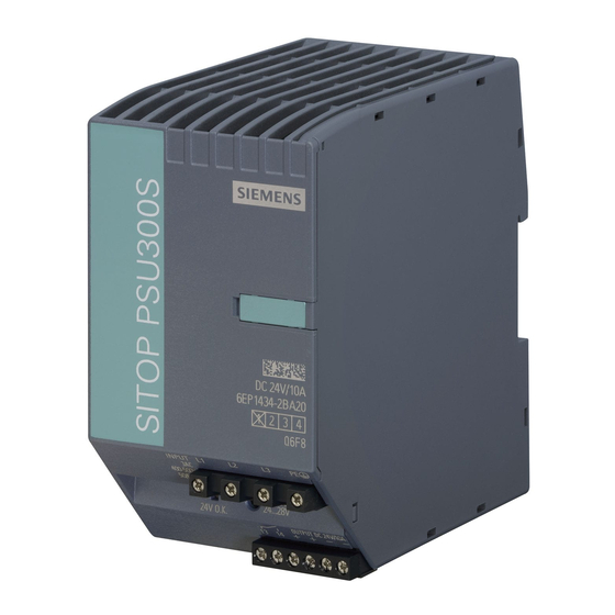
Figure 1 View of units The 3-phase SITOP PSU300S from the SITOP smart product line is a powerful, regulated standard power supply for automated machines and systems. In addition to a high efficiency, these low-profile power supply units have an outstanding overload behavior. - Page 4 Overview Ordering data The following device options are available: Regulated SITOP PSU300S power supply Type Order number Input 3AC 400 - 500 V, 6EP1433-2BA20 24 V/5 A output Input 3AC 400 - 500 V, 6EP1434-2BA20 24 V /10 A output...
-
Page 5: Table Of Contents
Technical data ............................35 Input ............................35 Output ............................. 36 Efficiency ..........................40 Closed-loop control ......................... 42 Protection and monitoring ....................... 43 MTBF ............................43 Mechanical system ......................... 44 Accessories ..........................44 Dimension drawing ......................... 45 SITOP PSU300S Manual, 12.2016, C98130-A7587-A1-7-7629... - Page 6 Series connection for increased voltage ................57 Overload protection in the 24 V output circuit ................ 58 Protection against short-time voltage dips ................59 Protecting against longer power failures ................60 Environment ............................63 Service & Support ..........................65 SITOP PSU300S Manual, 12.2016, C98130-A7587-A1-7-7629...
-
Page 7: Safety Instructions
Before installation or maintenance work can begin, the system's main switch must be switched off and measures taken to prevent it being switched on again. If this instruction is not observed, touching live parts can result in death or serious injury. SITOP PSU300S Manual, 12.2016, C98130-A7587-A1-7-7629... - Page 8 Safety instructions SITOP PSU300S Manual, 12.2016, C98130-A7587-A1-7-7629...
-
Page 9: Description, Device Design, Dimension Drawing
Description, device design, dimension drawing Device description SITOP PSU300S is a primary-clocked power supply for connection to a 3-phase AC line supply. An electronically regulated DC voltage that can be set via a potentiometer is available at the output of the device. The output of the device is isolated, no-load proof and short-circuit proof. -
Page 10: Connections And Terminal Designation
13, 14 (24 V O.K.) *1) Do not subject the end stop to higher loads Figure 2-2 Terminal data for 6EP1433-2BA20 and 6EP1434-2BA20 *1) Do not subject the end stop to higher loads Figure 2-3 Terminal data for 6EP1436-2BA10 SITOP PSU300S Manual, 12.2016, C98130-A7587-A1-7-7629... - Page 11 Description, device design, dimension drawing 2.2 Connections and terminal designation *1) Do not subject the end stop to higher loads Figure 2-4 Terminal data for 6EP1437-2BA20 SITOP PSU300S Manual, 12.2016, C98130-A7587-A1-7-7629...
-
Page 12: Potentiometer
For notes on actuating the potentiometer (screwdriver, torque), see Figure 2-2 Terminal data for 6EP1433-2BA20 and 6EP1434-2BA20 (Page 10), Figure 2-3 Terminal data for 6EP1436- 2BA10 (Page 10) and Figure 2-4 Terminal data for 6EP1437-2BA20 (Page 11) SITOP PSU300S Manual, 12.2016, C98130-A7587-A1-7-7629... -
Page 13: Status Displays And Signaling
(reset after approximately 120 s by switching off and on again). When 6EP1433-2BA20 and contact 13 - 14 opened 6EP1433-2BA20 devices trip as a result of an overtemperature condition, these devices (quiescent position) automatically start again after they have cooled down. SITOP PSU300S Manual, 12.2016, C98130-A7587-A1-7-7629... -
Page 14: Block Diagram
Description, device design, dimension drawing 2.5 Block diagram Block diagram Figure 2-7 Block diagram for 6EP1433-2BA20 and 6EP1434-2BA20 SITOP PSU300S Manual, 12.2016, C98130-A7587-A1-7-7629... - Page 15 Description, device design, dimension drawing 2.5 Block diagram Figure 2-8 Block diagram for 6EP1436-2BA10 and 6EP1437-2BA10 SITOP PSU300S Manual, 12.2016, C98130-A7587-A1-7-7629...
-
Page 16: Dimensions And Weight
Description, device design, dimension drawing 2.6 Dimensions and weight Dimensions and weight Figure 2-9 Dimension drawing 6EP1433-2BA20 Figure 2-10 Dimension drawing 6EP1434-2BA20 SITOP PSU300S Manual, 12.2016, C98130-A7587-A1-7-7629... - Page 17 70 × 125 × 120 90 × 145 × 150 145 × 145 × 150 (W × H × D) in mm Weight Approx. 0.5 kg Approx. 0.7 kg Approx. 1.6 kg approx. 3.1 kg SITOP PSU300S Manual, 12.2016, C98130-A7587-A1-7-7629...
- Page 18 Description, device design, dimension drawing 2.6 Dimensions and weight SITOP PSU300S Manual, 12.2016, C98130-A7587-A1-7-7629...
-
Page 19: Mounting/Removal
WARNING Installing the device in a housing or a control cabinet The SITOP PSU300S power supply is a built-in device. It must be installed in a housing or control cabinet, to which only qualified personnel have access. The device can be mounted in a control cabinet on standard mounting rails (see Chapter... - Page 20 If the device is to be used in a hazardous zone (Ex II 3G Ex nA nC IIC T3; Ex II 3G Ex nA nC IIC T4) it must be installed in a distribution box with degree of protection IP54 or higher. SITOP PSU300S Manual, 12.2016, C98130-A7587-A1-7-7629...
-
Page 21: Mounting Position, Mounting Clearances
No space is required at the side. Output current as a function of the ambient temperature and mounting height Figure 4-1 6EP1433-2BA20: Output current in the standard mounting position Figure 4-2 6EP1434-2BA20: Output current in the standard mounting position SITOP PSU300S Manual, 12.2016, C98130-A7587-A1-7-7629... - Page 22 4.1 Standard mounting position Figure 4-3 6EP1436-2BA10: Output current in the standard mounting position Figure 4-4 6EP1437-2BA20: Output current in the standard mounting position Figure 4-5 Altitude derating Details see chapter Ambient conditions (Page 51) SITOP PSU300S Manual, 12.2016, C98130-A7587-A1-7-7629...
-
Page 23: Other Mounting Positions
Particularly when installing on a vertically fastened standard mounting rail, additional measures may be required, e.g. to prevent the device from slipping on the standard mounting rail. 4.2.1 6EP1433-2BA20 Figure 4-6 Mounting position (1) Figure 4-7 Mounting position (2) SITOP PSU300S Manual, 12.2016, C98130-A7587-A1-7-7629... - Page 24 Mounting position, mounting clearances 4.2 Other mounting positions Figure 4-8 Mounting position (3) Figure 4-9 Mounting position (4) Figure 4-10 Mounting position (5) SITOP PSU300S Manual, 12.2016, C98130-A7587-A1-7-7629...
-
Page 25: 6Ep1434-2Ba20
Mounting position, mounting clearances 4.2 Other mounting positions 4.2.2 6EP1434-2BA20 Figure 4-11 Mounting position (1) Figure 4-12 Mounting position (2) Figure 4-13 Mounting position (3) SITOP PSU300S Manual, 12.2016, C98130-A7587-A1-7-7629... - Page 26 Mounting position, mounting clearances 4.2 Other mounting positions Figure 4-14 Mounting position (4) Figure 4-15 Mounting position (5) SITOP PSU300S Manual, 12.2016, C98130-A7587-A1-7-7629...
-
Page 27: 6Ep1436-2Ba10
Mounting position, mounting clearances 4.2 Other mounting positions 4.2.3 6EP1436-2BA10 Figure 4-16 Mounting position (1) Figure 4-17 Mounting position (2) Figure 4-18 Mounting position (3) SITOP PSU300S Manual, 12.2016, C98130-A7587-A1-7-7629... - Page 28 Mounting position, mounting clearances 4.2 Other mounting positions Figure 4-19 Mounting position (4) Figure 4-20 Mounting position (5) SITOP PSU300S Manual, 12.2016, C98130-A7587-A1-7-7629...
-
Page 29: 6Ep1437-2Ba20
Mounting position, mounting clearances 4.2 Other mounting positions 4.2.4 6EP1437-2BA20 Figure 4-21 Mounting position (1) Figure 4-22 Mounting position (2) Figure 4-23 Mounting position (3) SITOP PSU300S Manual, 12.2016, C98130-A7587-A1-7-7629... - Page 30 Mounting position, mounting clearances 4.2 Other mounting positions Figure 4-24 Mounting position (4) Figure 4-25 Mounting position (5) SITOP PSU300S Manual, 12.2016, C98130-A7587-A1-7-7629...
-
Page 31: Installation
Line-side connection The SITOP PSU300S power supply is designed for connection to a 3-phase AC line supply (TN or TT system according to VDE 0100 T 300 / IEC 364-3) with a rated voltage of 3-phase 400 - 500 VAC, 50 - 60 Hz. - Page 32 Installation 5.1 Line-side connection Protection SITOP PSU300S Required line-side protection 6EP1433-2BA20 3-pole coupled miniature circuit breaker (IEC 898) characteristic C, 3 - 16 A 3RV2011-1DA10 circuit breaker, thermal overload release setting: 3 A 3RV2711-1DD10 circuit breaker (branch circuit protection according to UL 489)
-
Page 33: Output-Side Connection
5.2 Output-side connection Output-side connection At its output, the SITOP PSU300S power supply provides an isolated (= non-grounded) SELV output voltage (Safety Extra Low Voltage). The output of the power supply is no-load, overload, and short-circuit proof. If an overload occurs, the electronic current limiting function limits the output current to a maximum value (refer to Chapter Technical data (Page 35)). - Page 34 Installation 5.2 Output-side connection SITOP PSU300S Manual, 12.2016, C98130-A7587-A1-7-7629...
-
Page 35: Technical Data
3RV2011- tic C or circuit breaker 1DA10 (setting 6 A) or 3RV2011-1DA10 (set- 3RV2711-1DD10 ting 3 A) or 3RV2711- (UL 489-listed, DIVQ) 1DD10 (UL 489-listed, DIVQ) Overvoltage strength 2.3 × U 1.3 ms in rated SITOP PSU300S Manual, 12.2016, C98130-A7587-A1-7-7629... -
Page 36: Output
Using a potentiometer Max. 120 W Max. 240 W Max. 480 W Max. 960 W Remark • Status display LED green for "24V O.K." Signaling Relay contact (NO contact, rating 60 VDC/0.3 A) for "24V O.K." SITOP PSU300S Manual, 12.2016, C98130-A7587-A1-7-7629... - Page 37 (Extra Power) Output characteristic See Figure 6-3 Output See Figure 6-4 Output See Figure 6-5 Output See Figure 6-6 Output characteristic characteristic characteristic characteristic 6EP1433-2BA20 6EP1434-2BA20 6EP1436-2BA10 6EP1437-2BA20 (Page 38) (Page 38) (Page 39) (Page 39) SITOP PSU300S Manual, 12.2016, C98130-A7587-A1-7-7629...
- Page 38 Technical data 6.2 Output Figure 6-2 Startup delay/voltage rise Figure 6-3 Output characteristic 6EP1433-2BA20 Figure 6-4 Output characteristic 6EP1434-2BA20 SITOP PSU300S Manual, 12.2016, C98130-A7587-A1-7-7629...
- Page 39 For 6EP1436-2BA10 and 6EP1437-2BA20, the following applies: When the output voltage falls below approx. 10 V, the device switches off, and initiates an automatic restart. This response is repeated as long as the overload condition is present. SITOP PSU300S Manual, 12.2016, C98130-A7587-A1-7-7629...
-
Page 40: Efficiency
91.5 % , approx. out rated out rated Power loss at 12.6 W 24 W 47 W 89 W , approx. out rated out rated No-load operation power 2.5 W loss, approx. Figure 6-7 Efficiency 6EP1433-2BA20 SITOP PSU300S Manual, 12.2016, C98130-A7587-A1-7-7629... - Page 41 Technical data 6.3 Efficiency Figure 6-8 Efficiency 6EP1434-2BA20 Figure 6-9 Efficiency 6EP1436-2BA10 SITOP PSU300S Manual, 12.2016, C98130-A7587-A1-7-7629...
-
Page 42: Closed-Loop Control
Load step regulation time 3 ms 2 ms 1 ms 50 to 100%, typ. Load step regulation time 3 ms 2 ms 1 ms 100 to 50%, typ. Regulation time / maximum 10 ms 10 ms 10 ms SITOP PSU300S Manual, 12.2016, C98130-A7587-A1-7-7629... -
Page 43: Protection And Monitoring
1500000 h) at 40 °C, 1450000 h) at 40 °C, rated load, 24 hour 700000 h) at 40 °C, rated load, 24 hour rated load, 24 hour operation rated load, 24 hour operation operation operation SITOP PSU300S Manual, 12.2016, C98130-A7587-A1-7-7629... -
Page 44: Mechanical System
6EP1436-2BA10 (24 V/20 A) 6EP1437-2BA20 (24 V/40 A) Electrical accessories Redundancy module, buffer module, diagnostics module SITOP select (for 6EP1433-2BA20 only PSE200U) or DC USV Mechanical accessories Device identification labels 20 mm × 7 mm, pastel turquoise 3RT1900-1SB20 SITOP PSU300S Manual, 12.2016, C98130-A7587-A1-7-7629... -
Page 45: Dimension Drawing
Technical data 6.9 Dimension drawing Dimension drawing See Section Dimensions and weight (Page 16) CAD data that can be downloaded from the Internet: 6EP1433-2BA20 (http://www.automation.siemens.com/bilddb/index.aspx?objKey=G_KT01_XX_01098) 6EP1434-2B20 (http://www.automation.siemens.com/bilddb/index.aspx?objKey=G_KT01_XX_01101) 6EP1436-2BA10 (http://www.automation.siemens.com/bilddb/index.aspx?objKey=G_KT01_XX_00408) 6EP1437-2BA20 (http://www.automation.siemens.com/bilddb/index.aspx?objKey=G_KT01_XX_00571) SITOP PSU300S Manual, 12.2016, C98130-A7587-A1-7-7629... - Page 46 Technical data 6.9 Dimension drawing SITOP PSU300S Manual, 12.2016, C98130-A7587-A1-7-7629...
-
Page 47: Safety, Approvals, Emc
Transformer according to EN 61558-2-16 Protection class Class I Degree of protection (EN 60529) IP20 Leakage current, typ. 0.4 mA 1 mA Leakage current, max. 3.5 mA Test voltage See Table 7-1 Test voltage (Page 48) SITOP PSU300S Manual, 12.2016, C98130-A7587-A1-7-7629... -
Page 48: Test Voltage
Field test 2200 V DC 2200 V DC 500 V DC 1500 V AC 1500 V AC 350 V AC Remark: Tripping current for DC measurement: 0 mA Tripping current for AC measurement: < 100 mA SITOP PSU300S Manual, 12.2016, C98130-A7587-A1-7-7629... -
Page 49: Approvals
IECex EPS 14.0072X IECex EPS 14.0071X PTZ 16 ATEX 0001 X EPS 10 ATEX 1 255 X EPS 11 ATEX 1 309 X CB approval Yes, (IEC 60950-1) SEMI F47 compliance fulfilled Marine approvals GL, ABS SITOP PSU300S Manual, 12.2016, C98130-A7587-A1-7-7629... -
Page 50: Emc
100% for 5000 ms 100% for 5000 ms Emitted interference EN 55022 Class B Line harmonics limita- EN 61000-3-2 Class A tion Generic standards EN 61000-6-2 Immunity for industrial environments EN 61000-6-3 Emission for residential areas SITOP PSU300S Manual, 12.2016, C98130-A7587-A1-7-7629... -
Page 51: Ambient Conditions
2 g acceleration in the range 8.4 - 150 Hz Comment: for 6EP1437-2BA20 with EZ 1: 1.3 g acceleration in the range 8.4 - 150 Hz Tested according to EN 60068-2-27 shock, test Ea: • acceleration 150 m/s , test duration 11 ms SITOP PSU300S Manual, 12.2016, C98130-A7587-A1-7-7629... - Page 52 Figure 4-5 Altitude derating (Page 22) Overvoltage category: • II up to 2000 m (EN 60950-1) I from 2000 m up to 6000 m (EN 60950-1) Storage: 1080 - 660 hPa (-1000 - 3500 m) • SITOP PSU300S Manual, 12.2016, C98130-A7587-A1-7-7629...
-
Page 53: Applications
50 mV. Figure 9-1 Parallel connection Note It is not permissible to take into account simultaneous overload capability (Extra-Power 150% for 5 s/min) of several power supplies connected in parallel when configuring the power supply system. SITOP PSU300S Manual, 12.2016, C98130-A7587-A1-7-7629... - Page 54 For this purpose, a suitable protective circuit (e.g. decoupling diode or DC-conform circuit breaker) must be installed between each "+" terminal of the power supply and the common connection point. SITOP PSU300S Manual, 12.2016, C98130-A7587-A1-7-7629...
-
Page 55: Parallel Connection For Redundancy
Figure 9-2 Redundant configuration with two power supplies and SITOP PSE202U redundancy module Figure 9-3 Redundant configuration with two power supplies and two SITOP PSE202U redundancy modules SITOP PSU300S Manual, 12.2016, C98130-A7587-A1-7-7629... - Page 56 Applications 9.2 Parallel connection for redundancy You can find additional information at: SITOP PSE202U manual (https://support.industry.siemens.com/cs/ww/en/view/42248598) SITOP PSU300S Manual, 12.2016, C98130-A7587-A1-7-7629...
-
Page 57: Series Connection For Increased Voltage
When connecting two power supplies in series, the continuous, permissible SELV voltage of a maximum of 60 VDC according to EN 60950-1 cannot be guaranteed in the case of a fault. Figure 9-4 Series connection SITOP PSU300S Manual, 12.2016, C98130-A7587-A1-7-7629... -
Page 58: Overload Protection In The 24 V Output Circuit
SIMATIC S7-1200/1500/300/400, for STEP 7 Classic and TIA Portal at no charge. You can find additional information at: Manual SITOP selectivity modules (https://support.industry.siemens.com/cs/ww/en/view/108989004) Figure 9-5 Electronic protection of 24 V loads using the SITOP PSE200U selectivity module SITOP PSU300S Manual, 12.2016, C98130-A7587-A1-7-7629... -
Page 59: Protection Against Short-Time Voltage Dips
5 A. This time can be increased a multiple number of times by connecting buffer modules in parallel; the maximum buffer time is 10 s. You can find additional information at: SITOP PSE201U manual (https://support.industry.siemens.com/cs/ww/en/view/41129219) Figure 9-6 Buffering brief power failures using the SITOP PSE201U buffer module SITOP PSU300S Manual, 12.2016, C98130-A7587-A1-7-7629... -
Page 60: Protecting Against Longer Power Failures
Using the free-of-charge SITOP DC-UPS software tool, DC-UPS systems can be simply integrated into PC-based automation solutions. This supports further processing of the status signals and safely running down the PC. You can find additional information at: Manual, DC UPS with capacitors (https://support.industry.siemens.com/cs/ww/en/ps/18042/man) SITOP PSU300S Manual, 12.2016, C98130-A7587-A1-7-7629... - Page 61 – make it easy to integrate operating and diagnostics information into STEP 7 user programs. Preconfigured UPS faceplates for WinCC visualization can be downloaded at no charge. You can find additional information at: DC UPS SITOP UPS1600/UPS1100 Manual (https://support.industry.siemens.com/cs/ww/en/view/84977415) SITOP PSU300S Manual, 12.2016, C98130-A7587-A1-7-7629...
- Page 62 Applications 9.6 Protecting against longer power failures SITOP PSU300S Manual, 12.2016, C98130-A7587-A1-7-7629...
-
Page 63: Environment
The devices are in conformance with RoHS. As a rule, only non-silicon precipitating materials are used. Disposal guidelines Packaging and packaging aids can and should always be recycled. The product itself may not be disposed of as domestic refuse. SITOP PSU300S Manual, 12.2016, C98130-A7587-A1-7-7629... - Page 64 Environment SITOP PSU300S Manual, 12.2016, C98130-A7587-A1-7-7629...
-
Page 65: Service & Support
● Telephone: + 49 (0) 911 895 7222 ● E-Mail (mailto:support.automation@siemens.com) ● Internet: Online support request form (http://www.siemens.de/automation/support-request) Technical documentation on the Internet Operating instructions and manuals for SITOP are available in the Internet: Operating instructions/manuals (http://www.siemens.com/sitop/manuals) SITOP power supply homepage General news about our power supplies is available in the Internet at the SITOP home page: SITOP (http://www.siemens.com/sitop) - Page 66 Service & Support Contact persons If you have any questions regarding the use of our products, then contact the Siemens contact person in your regional Siemens sales office. You can find these addresses as follows: ● On the Internet (http://www.automation.siemens.com/partner) ●...