Table of Contents
Advertisement
This service information is designed for experienced repair technicians only and is not designed for use by the general public.
It does not contain warnings or cautions to advise non-technical individuals of potential dangers in attempting to service a product.
Products powered by electricity should be serviced or repaired only by experienced professional technicians. Any attempt to service
or repair the products dealt with in this service information by anyone else could result in serious injury or death.
Indoor Unit
CS-PC9QKH
CS-PC12QKH
CS-PC18QKH
CS-PC24QKH
CS-PC28QKH
WARNING
Order No: PAPAMY1312019CE
Outdoor Unit
CU-PC9QKH
CU-PC12QKH
CU-PC18QKH
CU-PC24QKH
CU-PC28QKH
Destination
Myanmar
South East Asia
North Africa
Bangladesh
© Panasonic Corporation 2013
Advertisement
Table of Contents

Related Manuals for Panasonic CS-PC12QKH


Summary of Contents for Panasonic CS-PC12QKH
- Page 1 Products powered by electricity should be serviced or repaired only by experienced professional technicians. Any attempt to service or repair the products dealt with in this service information by anyone else could result in serious injury or death. © Panasonic Corporation 2013...
-
Page 2: Table Of Contents
17. Disassembly and Assembly Instructions ..72 CS-PC28QKH CU-PC28QKH ....24 17.1 CS-PC9/12QKH......... 72 8. Wiring Connection Diagram ......25 17.2 CS-PC18/24/28QKH........76 CS-PC9QKH CU-PC9QKH CS-PC12QKH CU-PC12QKH ....25 18. Technical Data ..........81 CS-PC18QKH CU-PC18QKH ....26 18.1 Thermostat Characteristics ....... 81 CS-PC24QKH CU-PC24QKH ....27 18.2 Operation Characteristics......82 CS-PC28QKH CU-PC28QKH ....28... -
Page 3: Safety Precautions
1. Safety Precautions Read the following “SAFETY PRECAUTIONS” carefully before perform any servicing. Electrical work must be installed or serviced by a licensed electrician. Be sure to use the correct rating of the power plug and main circuit for the model installed. ... - Page 4 20. After completion of installation or service, confirm there is no leakage of refrigerant gas. It may generate toxic gas when the refrigerant contacts with fire. 21. Ventilate if there is refrigerant gas leakage during operation. It may cause toxic gas when the refrigerant contacts with fire. 22.
-
Page 5: Specification
2. Specification Indoor CS-PC9QKH (Others/S. E. ASIA) CS-PC12QKH (Others/S. E. ASIA) Model Outdoor CU-PC9QKH (Others/S. E. ASIA) CU-PC12QKH (Others/S. E. ASIA) Performance Test Condition NEW JIS NEW JIS Phase, Hz Single, 50 Single, 50 Power Supply 2.65 2.70 3.49 3.54... - Page 6 Indoor CS-PC9QKH (Others/S. E. ASIA) CS-PC12QKH (Others/S. E. ASIA) Model Outdoor CU-PC9QKH (Others/S. E. ASIA) CU-PC12QKH (Others/S. E. ASIA) Height(I/D / O/D) mm (inch) 290 (11-7/16) / 511 (20-1/8) 290 (11-7/16) / 511 (20-1/8) Dimension Width (I/D / O/D) mm (inch)
- Page 7 Indoor CS-PC9QKH (MYANMAR) CS-PC12QKH (MYANMAR) Model Outdoor CU-PC9QKH (MYANMAR) CU-PC12QKH (MYANMAR) Performance Test Condition NEW JIS NEW JIS Phase, Hz Single, 50 Single, 50 Power Supply 2.65 2.70 3.49 3.54 Capacity Btu/h 9040 9210 11900 12100 kJ/h 9540 9720 12560...
- Page 8 Indoor CS-PC9QKH (MYANMAR) CS-PC12QKH (MYANMAR) Model Outdoor CU-PC9QKH (MYANMAR) CU-PC12QKH (MYANMAR) Height(I/D / O/D) mm (inch) 290 (11-7/16) / 511 (20-1/8) 290 (11-7/16) / 511 (20-1/8) Dimension Width (I/D / O/D) mm (inch) 850 (33-15/32) / 650 (25-19/32) 850 (33-15/32) / 650 (25-19/32)
- Page 9 Indoor CS-PC18QKH (Others/S. E. ASIA) CS-PC24QKH (Others/S. E. ASIA) Model Outdoor CU-PC18QKH (Others/S. E. ASIA) CU-PC24QKH (Others/S. E. ASIA) Performance Test Condition NEW JIS NEW JIS Phase, Hz Single, 50 Single, 50 Power Supply 5.28 5.30 6.93 7.03 Capacity Btu/h 18000 18100 23600...
- Page 10 Indoor CS-PC18QKH (Others/S. E. ASIA) CS-PC24QKH (Others/S. E. ASIA) Model Outdoor CU-PC18QKH (Others/S. E. ASIA) CU-PC24QKH (Others/S. E. ASIA) Height(I/D / O/D) mm (inch) 290 (11-7/16) / 542 (21-11/32) 290 (11-7/16) / 695 (27-3/8) Dimension Width (I/D / O/D) mm (inch) 1070 (42-5/32) / 780 (30-23/32) 1070 (42-5/32) / 875 (34-15/32) Depth (I/D / O/D)
- Page 11 Indoor CS-PC18QKH (MYANMAR) CS-PC24QKH (MYANMAR) Model Outdoor CU-PC18QKH (MYANMAR) CU-PC24QKH (MYANMAR) Performance Test Condition NEW JIS NEW JIS Phase, Hz Single, 50 Single, 50 Power Supply 5.28 5.30 6.93 7.03 Capacity Btu/h 18000 18100 23600 24000 kJ/h 19010 19080 24950 25310 Running Current 12.2...
- Page 12 Indoor CS-PC18QKH (MYANMAR) CS-PC24QKH (MYANMAR) Model Outdoor CU-PC18QKH (MYANMAR) CU-PC24QKH (MYANMAR) Height(I/D / O/D) mm (inch) 290 (11-7/16) / 542 (21-11/32) 290 (11-7/16) / 695 (27-3/8) Dimension Width (I/D / O/D) mm (inch) 1070 (42-5/32) / 780 (30-23/32) 1070 (42-5/32) / 875 (34-15/32) Depth (I/D / O/D) mm (inch) 240 (9-15/32) / 289 (11-13/32)
- Page 13 Indoor CS-PC28QKH (Others/S. E. ASIA) Model Outdoor CU-PC28QKH (Others/S. E. ASIA) Performance Test Condition NEW JIS Phase, Hz Single, 50 Power Supply 7.90 8.00 Capacity Btu/h 26900 27300 kJ/h 28440 28800 Running Current 14.0 13.1 Input Power 2.99k 3.04k 2.64 2.63 Btu/hW 9.00...
- Page 14 Indoor CS-PC28QKH (Others/S. E. ASIA) Model Outdoor CU-PC28QKH (Others/S. E. ASIA) Height(I/D / O/D) mm (inch) 290 (11-7/16) / 750 (29-17/32) Dimension Width (I/D / O/D) mm (inch) 1070 (42-5/32) / 875 (34-15/32) Depth (I/D / O/D) mm (inch) 240 (9-15/32) / 345 (13-19/32) Weight Net (I/D / O/D) kg (lb)
-
Page 15: Features
3. Features Long Installation Piping CS/CU-PC9QK long piping up to 10 meters. CS/CU-PC12QK long piping up to 15 meters. CS/CU-PC18QK, PC24QK long piping up to 25 meters. CS/CU-PC28QK long piping up to 30 meters. Easy to use remote control ... -
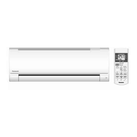
Page 16: Location Of Controls And Components
4. Location of Controls and Components Indoor Unit Outdoor Unit Remote Control... -
Page 17: Dimensions
5. Dimensions Indoor Unit 5.1.1 CS-PC9QKH CS-PC12QKH... - Page 18 5.1.2 CS-PC18QKH CS-PC24QKH CS-PC28QKH...
-
Page 19: Outdoor Unit
Outdoor Unit 5.2.1 CU-PC9QKH CU-PC12QKH 5.2.2 CU-PC18QKH... - Page 20 5.2.3 CU-PC24QKH 5.2.4 CU-PC28QKH...
-
Page 21: Refrigeration Cycle Diagram
6. Refrigeration Cycle Diagram... -
Page 22: Block Diagram
7. Block Diagram CS-PC9QKH CU-PC9QKH CS-PC12QKH CU-PC12QKH CS-PC18QKH CU-PC18QKH... -
Page 23: Cs-Pc24Qkh Cu-Pc24Qkh
CS-PC24QKH CU-PC24QKH... -
Page 24: Cs-Pc28Qkh Cu-Pc28Qkh
CS-PC28QKH CU-PC28QKH... -
Page 25: Wiring Connection Diagram
8. Wiring Connection Diagram CS-PC9QKH CU-PC9QKH CS-PC12QKH CU-PC12QKH Resistance of Indoor Fan Motor Windings Resistance of Indoor Fan Motor Windings CS-PC9QKH CS-PC12QKH MODEL MODEL Others/S. E. Asia Myanmar Others/S. E. Asia Myanmar CONNECTION CWA921562 CWA921559 CONNECTION CWA921561 CWA921559 BLUE-YELLOW 357 Ω... -
Page 26: Cs-Pc18Qkh Cu-Pc18Qkh
CS-PC18QKH CU-PC18QKH Resistance of Indoor Fan Motor Windings Resistance of Compressor Windings CS-PC18QKH CU-PC18QKH MODEL MODEL Others/S. E. Asia Myanmar Others/S. E. Asia Myanmar CONNECTION CWA921459 CONNECTION 2KS314D5CA06 2KS314D5BA06 BLUE-YELLOW 230 Ω 2.298 Ω 1.853 Ω YELLOW-RED 298 Ω 3.223 Ω 4.879 Ω... -
Page 27: Cs-Pc24Qkh Cu-Pc24Qkh
CS-PC24QKH CU-PC24QKH Resistance of Outdoor Fan Motor Windings Resistance of Compressor Windings MODEL CU-PC24QKH CU-PC24QKH MODEL CONNECTION CWA951697 Others/S. E. Asia Myanmar BLUE-YELLOW 70 Ω CONNECTION 2JS438D3GA04 2JS438D3EA04 YELLOW-RED 51 Ω 1.338 Ω 1.156 Ω YELLOW-ORANGE 69 Ω 2.420 Ω 2.997 Ω... -
Page 28: Cs-Pc28Qkh Cu-Pc28Qkh
CS-PC28QKH CU-PC28QKH Resistance of Outdoor Fan Motor Windings Resistance of Compressor Windings MODEL CU-PC28QKH MODEL CU-PC28QKH CONNECTION CWA951697 CONNECTION 2JD514E3AA03 BLUE-YELLOW 70 Ω 1.022 Ω YELLOW-RED 51 Ω 2.142 Ω YELLOW-ORANGE 69 Ω Note: Resistance at 20°C of ambient temperature. Note: Resistance at 20°C of ambient temperature. -
Page 29: Electronic Circuit Diagram
9. Electronic Circuit Diagram CS-PC9QKH CU-PC9QKH CS-PC12QKH CU-PC12QKH... -
Page 30: Cs-Pc18Qkh Cu-Pc18Qkh
CS-PC18QKH CU-PC18QKH... -
Page 31: Cs-Pc24Qkh Cu-Pc24Qkh
CS-PC24QKH CU-PC24QKH... -
Page 32: Cs-Pc28Qkh Cu-Pc28Qkh
CS-PC28QKH CU-PC28QKH... -
Page 33: Printed Circuit Board
10. Printed Circuit Board 10.1 Indoor Unit 10.1.1 Main Printed Circuit Board 10.1.1.1 CS-PC9QKH CS-PC12QKH... - Page 34 10.1.1.2 CS-PC18QKH...
- Page 35 10.1.1.3 CS-PC24QKH...
- Page 36 10.1.1.4 CS-PC28QKH...
- Page 37 10.1.2 Indicator and Receiver Printed Circuit Board 10.1.2.1 CS-PC9QKH CS-PC12QKH 10.1.2.2 CS-PC18QKH CS-PC24QKH CS-PC28QKH...
-
Page 38: Installation Instruction
11.1.3 Indoor/Outdoor Unit Installation 11. Installation Instruction Diagram (For PC9QKH, PC12QKH, PC18QKH, PC24QKH only) 11.1 Select the Best Location 11.1.1 Indoor Unit Do not install the unit in excessive oil fume area such as kitchen, workshop and etc. There should not be any heat source or steam near the unit. -
Page 39: Indoor Unit
11.2 Indoor Unit 11.2.1 How to Fix Installation Plate The mounting wall shall be strong and solid enough to prevent it from the vibration. Dimension Model PC9***, PC12*** 480 mm 82 mm 425 mm 425 mm 93 mm 145 mm Dimension Model PC18***, PC24***... - Page 40 11.2.2 To Drill a Hole in the Wall and Install a Sleeve of Piping Insert the piping sleeve to the hole. Fix the bushing to the sleeve. Cut the sleeve until it extrudes about 15 mm from the wall. CAUTION When the wall is hollow, please be sure to use the sleeve for tube assembly to prevent dangers caused by mice biting the connection cable.
- Page 41 11.2.3 Indoor Unit Installation 11.2.3.1 For the Right Rear Piping 11.2.3.2 For the Right and Right Bottom Piping 11.2.3.3 For the Embedded Piping (This can be used for left rear piping and bottom piping also.)
-
Page 42: Connect The Cable To The Indoor Unit
11.2.4 Connect the Cable to the Indoor Unit The power supply cord, indoor and outdoor unit connection cable can be connected without removing the front grille. Install the indoor unit on the installing holder that mounted on the wall. Open the front panel and grille door by loosening the screw. Cable connection to the power supply through Isolating Devices (Disconnecting means). - Page 43 Remove the tapes and connect the power supply cord and connection cable between indoor unit and outdoor unit according to the diagram below. Secure the power supply cord and connection cable onto the control board with the holder. Close grille door by tighten with screw and close the front panel. Note: ...
-
Page 44: Outdoor Unit
11.3 Outdoor Unit 11.3.1 Install the Outdoor Unit After selecting the best location, start installation to Indoor/Outdoor Unit Installation Diagram. Fix the unit on concrete or rigid frame firmly and horizontally by bolt nut (ø10 mm). When installing at roof, please consider strong wind and earthquake. Please fasten the installation stand firmly with bolt or nails. - Page 45 FOR ENVIRONMENTAL PROTECTION, MANUFACTURER STRONGLY RECOMMENDS TO USE EVACUATION METHOD. 11.3.3 Evacuation of the Equipment Connect a charging hose with a push pin to the Low side of a charging set and the service port of the 3-way valve. Be sure to connect the end of the charging hose with the push pin to the service port. Connect the center hose of the charging set to a vacuum pump.
- Page 46 11.3.4 Air Purging of the Piping and Indoor The remaining air in the Refrigeration cycle which contains moisture may cause malfunction on the compressor. Remove the caps from the 2-way and 3-way valves. Remove the service-port cap from the 3-way valves. To open the valve, turn the valve stem of 2-way valve counter-clockwise approx.
- Page 47 11.3.6 Piping Insulation Please carry out insulation at pipe connection portion as mentioned in Indoor/Outdoor Unit Installation Diagram. Please wrap the insulated piping end to prevent water from going inside the piping. If drain hose or connecting piping is in the room (where dew may form), please increase the insulation by using POLY-E FOAM with thickness 6 mm or above.
-
Page 48: Installation Instruction
12. Installation Instruction 12.1.3 Indoor/Outdoor Unit Installation Diagram (For PC28QKH only) 12.1 Select the Best Location 12.1.1 Indoor Unit Do not install the unit in excessive oil fume area such as kitchen, workshop and etc. There should not be any heat source or steam near the unit. -
Page 49: Indoor Unit
12.2 Indoor Unit 12.2.1 How to Fix Installation Plate The mounting wall shall be strong and solid enough to prevent it from the vibration. Dimension Model PC28*** 590 mm 82 mm 539 mm 532 mm 219 mm 269 mm The centre of installation plate should be at more than 1 at right and left of the wall. The distance from installation plate edge to ceiling should more than 2. - Page 50 12.2.3 Indoor Unit Installation 12.2.3.1 For the Right Rear Piping 12.2.3.2 For the Right and Right Bottom Piping 12.2.3.3 For the Embedded Piping (This can be used for left rear piping and bottom piping also.)
- Page 51 12.2.4 Connect the Cable to the Indoor Unit The inside and outside connection cable can be connected without removing the front grille. Connecting cable between indoor unit and outdoor unit shall be approved polychloroprene sheathed 4 x 1.5 mm flexible cord, type designation 60245 IEC 57 or heavier cord.
- Page 52 12.2.5 Wire Stripping and Connecting Requirement...
-
Page 53: Outdoor Unit
12.3 Outdoor Unit 12.3.1 Install the Outdoor Unit After selecting the best location, start installation to Indoor/Outdoor Unit Installation Diagram. Fix the unit on concrete or rigid frame firmly and horizontally by bolt nut (ø10 mm). When installing at roof, please consider strong wind and earthquake. Please fasten the installation stand firmly with bolt or nails. - Page 54 FOR ENVIRONMENTAL PROTECTION, MANUFACTURER STRONGLY RECOMMENDS TO USE EVACUATION METHOD. 12.3.3 Evacuation of the Equipment Connect a charging hose with a push pin to the Low side of a charging set and the service port of the 3-way valve. Be sure to connect the end of the charging hose with the push pin to the service port. Connect the center hose of the charging set to a vacuum pump.
- Page 55 12.3.4 Air Purging of the Piping and Indoor The remaining air in the Refrigeration cycle which contains moisture may cause malfunction on the compressor. Remove the caps from the 2-way and 3-way valves. Remove the service-port cap from the 3-way valves. To open the valve, turn the valve stem of 2-way valve counter-clockwise approx.
-
Page 56: Piping Insulation
12.3.5 Connect the Cable to the Outdoor Unit Remove the control board cover from the unit by loosening the screw. Cable connection to the power supply through Isolating Devices (Disconnecting means). Connect the approved polychloroprene sheathed power supply cord 3 x 4.0 mm type designation 60245 IEC 57 or heavier cord to the terminal board, and connect the others end of the cable to Isolating Devices (Disconnecting means). -
Page 57: Operation Control
13. Operation Control 13.1 Cooling Operation Cooling operation can be set using remote control. This operation is applied to cool down the room temperature to the setting temperature set on the remote control. The remote control setting temperature, which takes the reading of intake air temperature sensor, can be adjusted from 16°C to 30°C. - Page 58 13.1.2 Cooling Operation Time Diagram (For PC18/24/28QKH)
-
Page 59: Soft Dry Operation
13.2 Soft Dry Operation Soft Dry operation can be set using remote control. Soft Dry operation is applied to dehumidify and to perform a gentle cooling to the room. This operation starts when the intake air temperature sensor reaches -1.5°C from the setting temperature on the remote control. - Page 60 13.2.2 Soft Dry Operation Time Diagram (For PC18/24/28QKH)
-
Page 61: Iauto Operation
Vane control is follow remote control setting. 13.4 Indoor Fan Speed Control Indoor fan speed can be set using remote control 13.4.1 Fan Speed Rotation Chart Speed Fan Speed (rpm) CS-PC9QKH CS-PC12QKH CS-PC18QKH CS-PC24QKH CS-PC28QKH 1180 1180 1270 1420 1520... - Page 62 Auto Fan Speed during cooling operation: Indoor fan will rotate alternately between off and on as shown in below diagram. At the beginning of each compressor starts operation, indoor fan speed increases gradually for deodorizing purpose. For the first time the compressor operates, indoor fan will be switched to Hi fan speed from Lo- after 70 seconds from the start of compressor.
-
Page 63: Outdoor Fan Speed Control
13.5 Outdoor Fan Speed Control Outdoor fan speed can be changes to Hi or Lo according to outdoor temperature. (For PC24/28QKH) There is only one speed for outdoor fan motor. (For PC9/12/18QKH) When the air conditioner is turned on, the compressor and the outdoor fan will operate simultaneously. ... -
Page 64: Horizontal Airflow Direction Control
13.6.2 Manual Control When the vertical airflow direction is set to Manual using the remote control, the automatic airflow is released and the airflow direction louver move up and down in the range shown in the diagram. The louver can be adjusted by pressing the button to the desired louver position. ... -
Page 65: Random Auto Restart Control
13.9 Random Auto Restart Control If there is a power failure during operation, the air conditioner will automatically restart after 3 to 4 minutes when the power is resumed. It will start with previous operation mode and airflow direction. ... -
Page 66: Protection Control
14. Protection Control 14.1 Restart Control (Time Delay Safety Control) When the thermo-off temperature (temperature which compressor stops to operate) is reached during: Cooling operation – the compressor stops for 3 minutes (minimum) before resume operation. Soft Dry operation – the compressor stops for 6 minutes (minimum) before resume operation. ... -
Page 67: Compressor Reverse Rotation Protection Control
(For PC9/12QKH) The current fan speed will change to freeze prevention speed after 70 seconds compressor on. The fan speed will be increased according to the indoor pipe temperature the figure below: RPM shift (ID temp) Pipe 7.0°C 6.0°C 5.0°C 4.0°C 3.0°C... -
Page 68: Servicing Mode
15. Servicing Mode 15.1 Auto OFF/ON Button Auto OFF/ON Auto OFF/ON Auto OFF/ON Button Pressed Button Pressed Button Pressed 5 sec 5 sec iAUTO Operation Test Run Operation Stop Various Setting Mode Stop (Forced Cooling Operation) “Beep” 2 x “Beep” iAUTO OPERATION MODE The iAUTO Operation will be activated immediately once the Auto OFF/ON button is pressed. -
Page 69: Remote Control Button
15.2 Remote Control Button 15.2.1 SET Button To check current remote control transmission code and store the transmission code to EEPROM: Press “Set” button for more than 10 seconds by using pointer Press “Timer Set” button until a “beep” sound is heard as confirmation of transmission code change 15.2.2 RESET ... -
Page 70: Troubleshooting Guide
16. Troubleshooting Guide 16.1 Refrigeration Cycle System In order to diagnose malfunctions, ensure the air conditioner is free Normal Pressure and Outlet Air Temperature (Standard) from electrical problems before inspecting the refrigeration cycle. Gas Pressure Outlet air Temperature Such problems include insufficient insulation, problem with the (kg/cm (°C) power source, malfunction of a compressor and a fan. -
Page 71: Diagnosis Methods Of A Malfunction Of A Compressor
16.1.1 Relationship Between the Condition of the Air Conditioner and Pressure and Electric Current Cooling Mode Condition of the air conditioner Low Pressure High Pressure Electric current during operation Insufficient refrigerant (gas leakage) Clogged capillary tube or ... -
Page 72: Disassembly And Assembly Instructions
17. Disassembly and Assembly Instructions WARNING High Voltage is generated in the electrical parts area by the capacitor. Ensure that the capacitor has discharged sufficiently before proceeding with repair work. Failure to heed this caution may result in electric shocks. 17.1 CS-PC9/12QKH 17.1.1 Indoor Electronic Controllers and Control Board Removal Procedures... - Page 73 17.1.1.3 To Remove Discharge Grille...
- Page 74 17.1.1.4 To Remove Control Board 17.1.1.5 To Remove Cross Flow Fan and Indoor Fan Motor...
-
Page 76: Cs-Pc18/24/28Qkh
WARNING High Voltage is generated in the electrical parts area by the capacitor. Ensure that the capacitor has discharged sufficiently before proceeding with repair work. Failure to heed this caution may result in electric shocks. 17.2 CS-PC18/24/28QKH 17.2.1 Indoor Electronic Controllers, Cross Flow Fan and Indoor Fan Motor Removal Procedures 17.2.1.1 To Remove Front Grille... - Page 77 17.2.1.3 To Remove Main Electronic Controller (Fig. 3)
- Page 78 17.2.1.4 To Remove Discharge Grille (Fig. 6) 17.2.1.5 To Remove Control Board (Fig. 7)
- Page 79 17.2.1.6 To Remove Cross Flow Fan and Indoor Fan Motor (Fig. 8) (Fig. 9)
- Page 80 (Fig. 10) (Fig. 11)
-
Page 81: Technical Data
18. Technical Data 18.1 Thermostat Characteristics Cooling Soft Dry... -
Page 82: Operation Characteristics
18.2 Operation Characteristics 18.2.1 CS-PC9QKH CU-PC9QKH Cooling Characteristic [Condition] Room temperature: 27°C (DBT), 19°C (WBT) Operation condition: High fan speed Piping length: 7.5 m... - Page 83 Piping Length Characteristic Cooling [Condition] Room temperature: 27°C (DBT), 19°C (WBT) Operation condition: High fan speed Outdoor temperature: 35°C (DBT), 24°C (WBT)
- Page 84 18.2.2 CSPC9QKH CUPC9QKH (Myanmar Only) Cooling Characteristic [Condition] Room temperature: 27°C (DBT), 19°C (WBT) Operation condition: High fan speed Piping length: 7.5 m...
- Page 85 Piping Length Characteristic Cooling [Condition] Room temperature: 27°C (DBT), 19°C (WBT) Operation condition: High fan speed Outdoor temperature: 35°C (DBT), 24°C (WBT)
- Page 86 18.2.3 CS-PC12QKH CU-PC12QKH Cooling Characteristic [Condition] Room temperature: 27°C (DBT), 19°C (WBT) Operation condition: High fan speed Piping length: 7.5 m...
- Page 87 Piping Length Characteristic Cooling [Condition] Room temperature: 27°C (DBT), 19°C (WBT) Operation condition: High fan speed Outdoor temperature: 35°C (DBT), 24°C (WBT)
- Page 88 18.2.4 CS-PC12QKH CU-PC12QKH (Myanmar Only) Cooling Characteristic [Condition] Room temperature: 27°C (DBT), 19°C (WBT) Operation condition: High fan speed Piping length: 7.5 m...
- Page 89 Piping Length Characteristic Cooling [Condition] Room temperature: 27°C (DBT), 19°C (WBT) Operation condition: High fan speed Outdoor temperature: 35°C (DBT), 24°C (WBT)
- Page 90 18.2.5 CS-PC18QKH CU-PC18QKH Cooling Characteristic [Condition] Room temperature: 27°C (DBT), 19°C (WBT) Operation condition: High fan speed Piping length: 5.0 m...
- Page 91 Piping Length Characteristic Cooling [Condition] Room temperature: 27°C (DBT), 19°C (WBT) Operation condition: High fan speed Outdoor temperature: 35°C (DBT), 24°C (WBT)
- Page 92 18.2.6 CS-PC18QKH CU-PC18QKH (Myanmar Only) Cooling Characteristic [Condition] Room temperature: 27°C (DBT), 19°C (WBT) Operation condition: High fan speed Piping length: 5.0 m...
- Page 93 Piping Length Characteristic Cooling [Condition] Room temperature: 27°C (DBT), 19°C (WBT) Operation condition: High fan speed Outdoor temperature: 35°C (DBT), 24°C (WBT)
- Page 94 18.2.7 CS-PC24QKH CU-PC24QKH Cooling Characteristic [Condition] Room temperature: 27°C (DBT), 19°C (WBT) Operation condition: High fan speed Piping length: 5.0 m...
- Page 95 Piping Length Characteristic Cooling [Condition] Room temperature: 27°C (DBT), 19°C (WBT) Operation condition: High fan speed Outdoor temperature: 35°C (DBT), 24°C (WBT)
- Page 96 18.2.8 CS-PC24QKH CU-PC24QKH (Myanmar Only) Cooling Characteristic [Condition] Room temperature: 27°C (DBT), 19°C (WBT) Operation condition: High fan speed Piping length: 5.0 m...
- Page 97 Piping Length Characteristic Cooling [Condition] Room temperature: 27°C (DBT), 19°C (WBT) Operation condition: High fan speed Outdoor temperature: 35°C (DBT), 24°C (WBT)
- Page 98 18.2.9 CS-PC28QKH CU-PC28QKH Cooling Characteristic [Condition] Room temperature: 27°C (DBT), 19°C (WBT) Operation condition: High fan speed Piping length: 5.0 m...
- Page 99 Piping Length Characteristic Cooling [Condition] Room temperature: 27°C (DBT), 19°C (WBT) Operation condition: High fan speed Outdoor temperature: 35°C (DBT), 24°C (WBT)
-
Page 100: Exploded View And Replacement Parts List
19. Exploded View and Replacement Parts List 19.1 Indoor Unit 19.1.1 CS-PC9QKH CS-PC12QKH Note The above exploded view is for the purpose of parts disassembly and replacement. The non-numbered parts are not kept as standard service parts. - Page 101 CS-PC9QKH SAFETY REF. NO. PART NAME & DESCRIPTION REMARK Myanmar Other/S.E.Asia CHASSIS COMPLETE CWD50C1829 ← FAN MOTOR CWA921559 CWA921562 CROSS FLOW FAN COMPLETE CWH02C1159 ← SCREW - CROSS FLOW FAN CWH551146 ← BEARING ASS’Y CWH64K007 ← EVAPORATOR CWB30C4606 ← FLARE NUT (LIQUID) CWT251026 ←...
- Page 102 CS-PC12QKH SAFETY REF. NO. PART NAME & DESCRIPTION REMARK Myanmar Other/S.E.Asia CHASSIS COMPLETE CWD50C1829 ← FAN MOTOR CWA921559 CWA921561 CROSS FLOW FAN COMPLETE CWH02C1159 ← SCREW - CROSS FLOW FAN CWH551146 ← BEARING ASS’Y CWH64K007 ← EVAPORATOR CWB30C4637 ← FLARE NUT (LIQUID) CWT251026 ←...
- Page 103 19.1.2 CS-PC18QKH CS-PC24QKH CS-PC28QKH Note The above exploded view is for the purpose of parts disassembly and replacement. The non-numbered parts are not kept as standard service parts.
- Page 104 CS-PC18QKH SAFETY REF. NO. PART NAME & DESCRIPTION REMARK Myanmar Other/S.E.Asia CHASSIS COMPLETE CWD50C1654 ← FAN MOTOR CWA921459 ← CROSS FLOW FAN COMPLETE CWH02C1077 ← BEARING ASS’Y CWH64K007 ← SCREW - CROSS FLOW FAN CWH551146 ← EVAPORATOR CWB30C4656 ← FLARE NUT (LIQUID) CWT251026 ←...
- Page 105 CS-PC24QKH SAFETY REF. NO. PART NAME & DESCRIPTION REMARK Myanmar Other/S.E.Asia CHASSIS COMPLETE CWD50C1654 ← FAN MOTOR ARW7627AC L6CBYYYL0039 CROSS FLOW FAN COMPLETE CWH02C1077 ← BEARING ASS’Y CWH64K007 ← SCREW - CROSS FLOW FAN CWH551146 ← EVAPORATOR CWB30C4331 ← FLARE NUT (LIQUID) CWT251026 ←...
- Page 106 CS-PC28QKH SAFETY REF. NO. PART NAME & DESCRIPTION REMARK Other/S.E.Asia CHASSIS COMPLETE CWD50C1654 FAN MOTOR L6CBYYYL0039 CROSS FLOW FAN COMPLETE CWH02C1077 BEARING ASS’Y CWH64K007 SCREW - CROSS FLOW FAN CWH551146 EVAPORATOR CWB30C4232 FLARE NUT (LIQUID) CWT251026 FLARE NUT (GAS) CWT251036 HOLDER SENSOR CWH32142 CONTROL BOARD CASING...
-
Page 107: Outdoor Unit
19.2 Outdoor Unit 19.2.1 CU-PC9QKH CU-PC12QKH Note The above exploded view is for the purpose of parts disassembly and replacement. The non-numbered parts are not kept as standard service parts. - Page 108 CU-PC9QKH SAFETY REF. NO. PART NAME & DESCRIPTION REMARK Myanmar Other/S.E.Asia CHASSIS ASS’Y CWD50K2241 ← SOUND PROOF MATERIAL CWG302403 ← FAN MOTOR BRACKET CWD541233 ← SCREW - FAN MOTOR BRACKET CWH551217 ← FAN MOTOR CWA951673 CWA951852 SCREW - FAN MOTOR MOUNT CWH55252J ←...
- Page 109 CU-PC12QKH SAFETY REF. NO. PART NAME & DESCRIPTION REMARK Myanmar Other/S.E.Asia CHASSIS ASS’Y CWD50K2241 ← SOUND PROOF MATERIAL CWG302882 ← FAN MOTOR BRACKET CWD541235 ← SCREW - FAN MOTOR BRACKET CWH551217 ← FAN MOTOR CWA951673 CWA951852 SCREW - FAN MOTOR MOUNT CWH55252J ←...
- Page 110 19.2.2 CU-PC18QKH Note The above exploded view is for the purpose of parts disassembly and replacement. The non-numbered parts are not kept as standard service parts.
- Page 111 CU-PC18QKH SAFETY REF. NO. PART NAME & DESCRIPTION REMARK Myanmar Other/S.E.Asia CHASSIS ASS’Y CWD50K2088 ← SOUND PROOF MATERIAL CWG302673 CWG302256 FAN MOTOR BRACKET CWD541030 ← SCREW - FAN MOTOR BRACKET CWH551217 ← FAN MOTOR CWA951851 CWA951688 SCREW - FAN MOTOR MOUNT CWH55252J ←...
- Page 112 19.2.3 CU-PC24QKH Note The above exploded view is for the purpose of parts disassembly and replacement. The non-numbered parts are not kept as standard service parts...
- Page 113 CU-PC24QKH SAFETY REF. NO. PART NAME & DESCRIPTION REMARK Myanmar Others/S.E.Asia CHASSIS ASS’Y CWD52K1248 ← SOUND PROOF MATERIAL CWG302406 ← FAN MOTOR BRACKET CWD541154 ← SCREW - FAN MOTOR BRACKET CWH551217 ← FAN MOTOR CWA951697 ← SCREW - FAN MOTOR MOUNT CWH55406J ←...
- Page 114 19.2.4 CU-PC28QKH Note The above exploded view is for the purpose of parts disassembly and replacement. The non-numbered parts are not kept as standard service parts.
- Page 115 CU-PC28QKH SAFETY REF. NO. PART NAME & DESCRIPTION REMARK Other/S.E.Asia CHASSIS ASS’Y CWD50K2100 SOUND PROOF MATERIAL CWG302408 FAN MOTOR BRACKET CWD541055 SCREW - FAN MOTOR BRACKET CWH551217 FAN MOTOR CWA951697 SCREW - FAN MOTOR MOUNT CWH55252J PROPELLER FAN ASS’Y CWH03K1017 NUT - PROPELLER FAN CWH561092 COMPRESSOR (50HZ, 220/240V)