Siemens SITRANS LUT400 Operating Instructions Manual
Ultrasonic controllers
Hide thumbs
Also See for SITRANS LUT400:
- Operating instructions manual (601 pages) ,
- Manual (140 pages) ,
- Application manual (16 pages)
Table of Contents
Troubleshooting

Related Manuals for Siemens SITRANS LUT400


Summary of Contents for Siemens SITRANS LUT400
- Page 1 Ultrasonic Controllers SITRANS LUT400 (HART) Operating Instructions Edition 12/2014...
- Page 2 The user is responsible for all changes and repairs made to the device by the user or the user’s agent. All new components are to be provided by Siemens Milltronics Process Instruments. Restrict repair to faulty components only.
-
Page 3: Table Of Contents
DIN-rail mount ...........................15 Preparation for cable entry ....................16 Cable routed through conduit..................16 Cable exposed and entering through the cable glands......... 17 SITRANS LUT400 wiring compartment ..................17 The Battery ............................17 Connecting ........................19 Safety notes for connection ....................19 Connecting SITRANS LUT400 ......................20 Wiring compartment ........................20... - Page 4 Remote mounted lid with extension cable ................29 Extension cable .........................30 Connecting in hazardous area installations .................31 Commissioning ........................33 Local Commissioning .........................33 Activating SITRANS LUT400 ......................33 The LCD Display ........................34 Measurement mode display: Normal operation PROGRAM mode display....................35 Key functions in Measurement mode ................ 35 Programming SITRANS LUT400 ....................35...
- Page 5 Vessel Shape and Dimensions ....................73 Characterization chart ......................73 Alarms ..............................76 Level .............................76 In-bounds/ Out-of-bounds Range ..................77 Temperature ..........................78 Switch (Discrete Input) Alarm ....................78 Fail-safe Fault Alarm ........................79 Flowrate ............................79 Pump Control ............................79 Pump Control options .......................80 Pump Control algorithms....................80 Setting a pump down (wet well) group ................80 Other Pump Control algorithms .....................82 Setting a pump up (reservoir) group ..................85...
- Page 6 Fail-safe and Simulation ..................... 122 HART status ........................122 Simulation process ...................... 122 Application test ........................123 SITRANS LUT400 Communication Systems ................124 LUT400 Communications (HART) ..................124 HART Version ........................ 124 Burst mode........................125 HART multi-drop mode....................125 SIMATIC PDM....................... 125 HART Electronic Device Description (EDD) ............125 HART Status ........................
- Page 7 Install a Transducer with a Narrower Beam............245 Fixed Reading ............................245 Obstructions in the Sound Beam ..................245 Nozzle Mountings ........................245 Set the SITRANS LUT400 to Ignore the Bad Echo ............246 Wrong Reading ..........................246 Types of Wrong Readings .....................246 Liquid Splashing ........................246 Adjust the Echo Algorithm ....................246...
- Page 8 Shaper Mode and Auto False Echo Suppression ..........260 Measurement Range ......................261 Measurement Response .......................262 Damping.......................... 262 Analog Output ............................263 Current Output Function (2.5.1.) ...................263 Loss of Echo (LOE) ........................263 Fail-safe Mode ......................263 Distance Calculation ........................264 Sound Velocity .........................264 Volume Calculation ...........................265 Pump Totalizers ..........................266 Inflow/Discharge Adjust ......................266...
-
Page 9: Introduction
Application examples The application examples used in this manual illustrate typical installations using SITRANS LUT400. As there is often a range of ways to approach an application, other configurations may also apply. In all examples, substitute your own application details. If the examples do not apply to your application, check the applicable parameter reference for the available options. -
Page 10: Change History
• Added Russian, Portuguese and Italian language 1.01.01 February 1, 2014 support. • Added user changeable password and First In, 1.02.00 December 1, 2014 First Out datalog option. Page 2 SITRANS LUT400 (HART) – OPERATING INSTRUCTIONS A5E33329501... -
Page 11: Safety Notes
WARNING: refer to accompanying documents (manual) for details. CAUTION: Observe electrostatic discharge precautions prior to handling electronic components within the wiring compartment. This symbol is used when there is no corresponding caution symbol on the product. A5E33329501 SITRANS LUT400 (HART) – OPERATING INSTRUCTIONS Page 3... -
Page 12: Fcc Conformity
US Installations only: Federal Communications Commission (FCC) rules WARNING: Changes or modifications not expressly approved by Siemens could void the user’s authority to operate the equipment. Notes: • This equipment has been tested and found to comply with the limits for a Class A digital device, pursuant to Part 15 of the FCC Rules. - Page 13 Testing and measurement techniques – Power frequency magnetic field immunity test. Electromagnetic Compatibility (EMC) Part 4-11: Testing and measurement techniques - voltage clips, EN61000-4-11: 2004 short interruptions and voltage variations immunity tests. A5E33329501 SITRANS LUT400 (HART) – OPERATING INSTRUCTIONS Page 5...
- Page 14 Notes Page 6 SITRANS LUT400 (HART) – OPERATING INSTRUCTIONS A5E33329501...
-
Page 15: Description
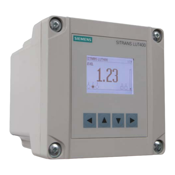
The series is compatible with Siemens full line of EchoMax Transducers, allowing an operating range of 0.3 to 60 meters (dependent on transducer). The SITRANS LUT400 has been coupled with a backlit Local User Interface (LUI) display featuring menu driven programming and a host of wizards for plug and play performance. -
Page 16: Models
Models The SITRANS LUT400 comes in three different models, depending on the application, level of performance and functionality required: • SITRANS LUT420 Level Controller - Level or volume measurement, basic pump control functions, and basic data logging capability • SITRANS LUT430 Pump and Flow Controller - Full suite of advanced control functionality, open channel flow monitoring, and basic data logging capability •... -
Page 17: Installing And Mounting
• Ambient temperature is always within -20 to +50 °C (-4 to +122 °F) • SITRANS LUT400 display window is at shoulder level, unless most interaction is through a SCADA system • Easy access to local push buttons is provided •... -
Page 18: Mounting Instructions
All configurations of the SITRANS LUT400 are shipped with a mounting back plate. SITRANS LUT400 has the option of a lid with a Local User Interface (LUI) display, a remote display for panel mount configuration, or a blank lid. The panel mount model comes with both a LUI display and a blank lid. - Page 19 Fasten with a screwdriver. Line up slotted features on back of device with clips on mounting back plate. Press the LUT400 flush against the back plate and slide downward to fasten in place. A5E33329501 SITRANS LUT400 (HART) – OPERATING INSTRUCTIONS Page 11...
-
Page 20: Remote Mounted Lid
4 panel mount fasteners provided extension cable SITRANS LUT400 SITRANS LUT400 Dimensions For a more detailed dimension drawing, see on page 255 Cutout Dimensions (for Remote Panel Mount) on page 256. Page 12 SITRANS LUT400 (HART) – OPERATING INSTRUCTIONS A5E33329501... -
Page 21: Pipe Mount
Note: Pipe mount fasteners not included. SITRANS LUT400 Dimensions For a more detailed dimension drawing, see on page 255. A5E33329501 SITRANS LUT400 (HART) – OPERATING INSTRUCTIONS Page 13... - Page 22 3" pipe size with M8 or 3/8" thread minimum: 3/4" pipe size with M6 or 1/4" thread • Hex Nuts: M6 or 1/4" to M8 or 3/8" • Washer: maximum: 16 mm or 13/16" outside diameter. Page 14 SITRANS LUT400 (HART) – OPERATING INSTRUCTIONS A5E33329501...
-
Page 23: Din-Rail Mount
Required DIN-rail dimensions: TH 35-7.5 or TH 35-15 per standard IEC 60715. • The DIN-rail MUST be able to support four times the weight of the SITRANS LUT400. Removing the enclosure From the front of the device, place screwdriver in slot at bottom of DIN-rail slide and pry downward. -
Page 24: Preparation For Cable Entry
Replace enclosure lid and tighten screws. SITRANS LUT400 cable entry holes knock-out tab groove for screwdriver (3 places) (3 places) SITRANS LUT400 Dimensions For a more detailed dimension drawing, see on page 255. Page 16 SITRANS LUT400 (HART) – OPERATING INSTRUCTIONS A5E33329501... -
Page 25: Cable Exposed And Entering Through The Cable Glands
The Battery The SITRANS LUT400 is supplied with one battery installed. The battery (BR2032) has a life expectancy of ten years, and is affected by ambient temperature. If the LUT400 loses input power, the battery will maintain operation of the device’s real time clock until power has been restored. - Page 26 Notes Page 18 SITRANS LUT400 (HART) – OPERATING INSTRUCTIONS A5E33329501...
-
Page 27: Connecting
HART FC375/475 or a computer running SIMATIC PDM, AMS Device Manager, FDT, or a web browser Customer Alarm, Pump, or Control Device Customer Device with Digital Output Display, PLC, Chart recorder, or other Control Device A5E33329501 SITRANS LUT400 (HART) – OPERATING INSTRUCTIONS Page 19... -
Page 28: Connecting Sitrans Lut400
Recommended torque on terminal clamping screws. Note: • 0.56 - 0.79 N m • 5 - 7 in-lbs Please do not overtighten the screws. Page 20 SITRANS LUT400 (HART) – OPERATING INSTRUCTIONS A5E33329501... -
Page 29: Power
IEC 61010-1. All field wiring must have insulation ratings suitable for the application. Important! Before applying power to the SITRANS LUT400 for the first time, ensure any connected alarm/control equipment is disabled until satisfactory system operation and performance is verified. NPUT... -
Page 30: Cables
• A circuit breaker or switch in the building installation, marked as the disconnect switch, must be in close proximity to the equipment and within easy reach of the operator, and must disconnect all current-carrying conductors. Cables The SITRANS LUT400 is designed to work with two conductor shielded transducer cables. Connection Cable Type... -
Page 31: Transducers
Warning: Hazardous voltage present on transducer terminals during operation. Notes: • Do not connect coaxial cable directly to SITRANS LUT400 due to high voltage transmitted on shield of coaxial cable • Do not connect the LUT400 shield and white transducer wires together; wire to separate terminals •... -
Page 32: Relays
TO OTHER 100 230V SLOW BLOW SIEMENS UNIT TO TRANSDUCER RELAYS mA OUT/HART BATTERY BR2032 DISPLAY RLY 1 RLY 2 RLY 3 SERVICE 4 to 20 mA Hart USB cable connection connection Page 24 SITRANS LUT400 (HART) – OPERATING INSTRUCTIONS A5E33329501... -
Page 33: Connecting Via Usb
LUT400. Data Logging may not occur, even after extension cable has been disconnected. (If a USB extension cable has been used in error, a power reset of the device is required to restart Data Logging.) A5E33329501 SITRANS LUT400 (HART) – OPERATING INSTRUCTIONS Page 25... -
Page 34: Connecting Hart
2. The nominal value for the HART resistor is 250 Ohm. For more information see application guide Working with HART , which can be downloaded from the product page of our website. Go to: www.siemens.com/sitransLUT400 under Support and click on Application Guides. Page 26 SITRANS LUT400 (HART) – OPERATING INSTRUCTIONS... -
Page 35: Level System Synchronization
• Interconnect the SYNC terminals of all level monitors. • Up to 16 Siemens devices can be synchronized together. For more information or assistance, contact Siemens or your local distributor. Go to: www.siemens.com/processautomation. A5E33329501 SITRANS LUT400 (HART) – OPERATING INSTRUCTIONS... -
Page 36: Discrete Inputs
Discrete inputs The SITRANS LUT400 has a 24V power bias (terminal 10) for use with the discrete inputs, or the discrete inputs can be wired using external power. DISCRETE INPUTS SYNC Discrete Inputs used with internal bias supply DISCRETE INPUTS SYNC Note: terminals 6 and 7 must be connected together. -
Page 37: Remote Mounted Lid With Extension Cable
Feed the free end of the extension cable through cable entry hole on blank lid. Connect extension cable to display cable on remote lid. A5E33329501 SITRANS LUT400 (HART) – OPERATING INSTRUCTIONS Page 29... -
Page 38: Extension Cable
Two cables can be connected together for an extension of up to 5 meters. It is recommended that the exposed extension cable be secured along a Note: wall, or run through conduit to prevent damage to device, should cable be accidentally subjected to stress. Page 30 SITRANS LUT400 (HART) – OPERATING INSTRUCTIONS A5E33329501... -
Page 39: Connecting In Hazardous Area Installations
Assembled in Canada with domestic and imported parts Assembled in Canada with domestic and imported parts CSA Class I, Div 2 connection drawing number A5E03936871 can be downloaded from the product page of our website at www.siemens.com/sitransLUT400. A5E33329501 SITRANS LUT400 (HART) – OPERATING INSTRUCTIONS... - Page 40 Notes Page 32 SITRANS LUT400 (HART) – OPERATING INSTRUCTIONS A5E33329501...
-
Page 41: Commissioning
Commissioning Local Commissioning SITRANS LUT400 is an easy to use, and quick to commission device, with its numerous wizards, and menu driven parameters. The parameters can be modified locally using the LCD and the local push buttons, also known as the Local User Interface (LUI). -
Page 42: The Lcd Display
Power up the device. SITRANS LUT400 automatically starts up in Measurement mode. A transition screen showing first the Siemens logo and then the current firmware revision of the LUI is displayed while the first measurement is being processed. The first time the device is configured, you will be prompted to select a language (English, German, French, Spanish, Chinese, Italian, Portuguese, or Russian). -
Page 43: Program Mode Display
Change parameter settings and set operating conditions to suit your specific application. Operation via SIMATIC PDM 6 (HART) (For remote operation, see on page 127 or Operation via AMS Device Manager (HART) on page 131.) A5E33329501 SITRANS LUT400 (HART) – OPERATING INSTRUCTIONS Page 35... - Page 44 Go to first parameter in the selected menu menu, or open next menu. RIGHT arrow parameter Open Edit mode. LEFT arrow menu or parameter Open parent menu. Page 36 SITRANS LUT400 (HART) – OPERATING INSTRUCTIONS 7ML1998MV01...
- Page 45 Review for accuracy. Key functions in Edit mode Name Function Selecting Scrolls to item. options UP or DOWN Alpha- - Increments or decrements digits arrow numeric - Toggles plus and minus sign editing A5E33329501 SITRANS LUT400 (HART) – OPERATING INSTRUCTIONS Page 37...
-
Page 46: Quick Start Wizards
Quick Start Wizards A Wizard provides an easy step-by-step Quick Start (QS) procedure that configures the device for a simple application. To configure the SITRANS LUT400 for applications of level, Quick Start Wizards via LUI volume (standard vessel shapes), or flow, use the on page 38 of this chapter. - Page 47 DOWN XPS 10 XPS 15 XCT 8 arrow to continue. XCT 12 At any time, you can press UP arrow go back, or LEFT arrow to cancel the wizard. A5E33329501 SITRANS LUT400 (HART) – OPERATING INSTRUCTIONS Page 39...
- Page 48 This screen is not part of the Quick Start when using SIMATIC PDM. Shows the type of Wizard to be executed. CANCEL, START Options Transducer Specifies the Siemens transducer connected to the device. NO TRANSDUCER, XRS-5, XPS-10, XPS-15, XCT-8, XCT-12, XPS-30, XPS-40, XLT-30, XLT-60, STH Options Default: NO TRANSDUCER...
- Page 49 For the purpose of this example, all values are assumed to be in meters (m). Note: High Calibration Point Distance from Sensor Reference Point to High Calibration Point: usually process full level. Range: 0.000 to 60.000 Value Default: 0.000 A5E33329501 SITRANS LUT400 (HART) – OPERATING INSTRUCTIONS Page 41...
- Page 50 If CANCEL is selected, no changes are written to the device.) To transfer Quick Start values to the device and return to Program menu, press DOWN arrow (Finish). Then press LEFT arrow three times to return to Measurement mode. Page 42 SITRANS LUT400 (HART) – OPERATING INSTRUCTIONS 7ML1998MV01...
- Page 51 - Vessel Shape - Dimension A - Units - Dimension L - High Calibration Point - Low Calibration Point - Response Rate Volume Wizard vessel volume complete - Volume Units - Maximum Volume A5E33329501 SITRANS LUT400 (HART) – OPERATING INSTRUCTIONS Page 43...
- Page 52 This parameter is only displayed if FIXED TEMPERATURE selected for Temperature Source. Vessel Shape Defines the vessel shape and allows the SITRANS LUT400 to calculate volume instead of level. If NONE is selected, no volume conversion is performed. Select the vessel shape matching the monitored vessel or reservoir.
- Page 53 L, USGAL, IMPGAL, CUM, USER DEFINED * Options Default: L * If USER DEFINED option selected, the value must be set after completing the 2.6.6. User Defined Unit wizard. See on page 149. A5E33329501 SITRANS LUT400 (HART) – OPERATING INSTRUCTIONS Page 45...
- Page 54 To transfer Quick Start values to the device and return to Program menu, press DOWN arrow (Finish). Then press LEFT arrow three times to return to Measurement mode. Page 46 SITRANS LUT400 (HART) – OPERATING INSTRUCTIONS 7ML1998MV01...
- Page 55 - Zero Head Offset - OCM Dimension 2 - OCM Dimension 3 - Flowrate Units - OCM Dimension 4 - Maximum Flow at 20 mA - Flowrate Decimal - Low Flow Cutoff A5E33329501 SITRANS LUT400 (HART) – OPERATING INSTRUCTIONS Page 47...
- Page 56 This screen is not part of the Quick Start when using SIMATIC PDM. Shows the type of Wizard to be executed. CANCEL, START Options Transducer Specifies the Siemens transducer connected to the device. NO TRANSDUCER, XRS-5, XPS-10, XPS-15, XCT-8, XCT-12, XPS-30, XPS-40, XLT-30, XLT-60, STH Options Default: NO TRANSDUCER Temperature Source Source of the temperature reading used to adjust the speed of sound.
- Page 57 Default: SLOW (0 1 M/MIN) Use a setting just faster than the maximum filling or emptying rate (whichever is greater). Slower settings provide higher accuracy, faster settings allow for more level fluctuations. A5E33329501 SITRANS LUT400 (HART) – OPERATING INSTRUCTIONS Page 49...
- Page 58 The Flow Slope used in the flow calculation formula. Range: -999.000 to 9999.000 Value Default: 0.000 Roughness Coefficient (PMD = ROUND PIPE) The Flow Roughness Coefficient used in the flow calculation formula. Range: -999.000 to 9999.000 Value Default: 0.000 Page 50 SITRANS LUT400 (HART) – OPERATING INSTRUCTIONS 7ML1998MV01...
- Page 59 2. 1 5.4.7. OCM Dimension 3 CREST HEIGHT P ( Rectangular Weir Contracted 2. 1 5.4.5. OCM Dimension 1 CREST WIDTH B ( Round Pipe 2. 1 5.4.5. OCM Dimension 1 PIPE INSIDE DIAMETER D ( A5E33329501 SITRANS LUT400 (HART) – OPERATING INSTRUCTIONS Page 51...
- Page 60 NO DIGITS, 1 DIGIT, 2 DIGITS, 3 DIGITS Options Default: NO DIGITS Low Flow Cutoff Eliminates totalizer activity for head levels at or below the cutoff value. Range: 0.000 to 60.000 Value Default: 0.000 Page 52 SITRANS LUT400 (HART) – OPERATING INSTRUCTIONS 7ML1998MV01...
- Page 61 Measurement mode. Note: Auto Zero Head It is strongly recommended that an be performed after 2.15.2. Auto Zero Head completion of the wizard to ensure best accuracy. See page 191. A5E33329501 SITRANS LUT400 (HART) – OPERATING INSTRUCTIONS Page 53...
- Page 62 If Relay Pump 1 = RELAY 2, then Relay Pump 2 = RELAY 3 Options If Relay Pump 1 = RELAY 3, then Relay Pump 2 = RELAY 2 (view only) Page 54 SITRANS LUT400 (HART) – OPERATING INSTRUCTIONS 7ML1998MV01...
- Page 63 Use the default value for new pumps, or set this value for existing pumps with accumulated run time. (This parameter displays only if a Service Ratio algorithm is selected for Pump Control Mode.) A5E33329501 SITRANS LUT400 (HART) – OPERATING INSTRUCTIONS Page 55...
- Page 64 Options written to the device.) To transfer values to the device and return to Program menu, press DOWN arrow (Finish). Then press LEFT arrow two times to return to Measurement mode. Page 56 SITRANS LUT400 (HART) – OPERATING INSTRUCTIONS 7ML1998MV01...
-
Page 65: Requesting An Echo Profile
Device Address Setting a device address is not necessary for local operation, but must be set if Device Address 4.1. configuring the SITRANS LUT400 for use on a HART network. See page 217. Testing the configuration After programming the device, it is recommended that you test the device to ensure that it performs to your specifications. -
Page 66: Application Examples
Fill rate = (Low Cal Pt. – High Cal Pt.) / fastest of fill or empty time = (15.5 m – 1 m) / 180 min. = 14.5 m /180 min. = 0.08 m/min. Page 58 SITRANS LUT400 (HART) – OPERATING INSTRUCTIONS 7ML1998MV01... -
Page 67: Flow Application Example
The Parshall Flume is considered an exponential device, therefore the supplier’s data sheet includes a flow exponent value of 1.522. The SITRANS LUT400, and the XRS-5 transducer have been installed 1.6 m above the channel beside the TS-3 external temperature sensor. - Page 68 Select relay to be used for fail-safe alarm. Assigned Relay (2.8.8.2.) Relay 1 Relay 1 is the dedicated alarm relay for the LUT400. Continue with sampler setup on next page. Page 60 SITRANS LUT400 (HART) – OPERATING INSTRUCTIONS 7ML1998MV01...
- Page 69 Fail-safe alarm. Default for control relay functions is Normally Normally Relay Logic (2.11.4.6.) Open. In this example, relay 2’s coil will be Nor- Open mally Open, and will close for 0.2 seconds. A5E33329501 SITRANS LUT400 (HART) – OPERATING INSTRUCTIONS Page 61...
- Page 70 Notes Page 62 SITRANS LUT400 (HART) – OPERATING INSTRUCTIONS 7ML1998MV01...
-
Page 71: General Operation
34. Starting measurement The SITRANS LUT400 is a single point device. The device starts in LEVEL mode with a preset of no transducer and a low calibration point of 60 meters. Change the following common parameters to reflect your application. -
Page 72: Relays
SITRANS LUT400 comes with extensive control and alarm functions described below. General introduction Three relays are provided on the SITRANS LUT400. Each relay may be independently assigned to one function (one or more functions for alarms), and has a corresponding status icon on the LCD. -
Page 73: Relay Function
If the ON setpoint is higher than the OFF setpoint, the relay operates as: • pump down control If the ON setpoint is lower than the OFF setpoint, the relay operates as: • pump up control A5E33329501 SITRANS LUT400 (HART) – OPERATING INSTRUCTIONS Page 65... -
Page 74: Miscellaneous
Since pumps do not run when in fail-safe, then the external totalizer will in general not operate either. If a fail-safe condition occurs during a pump cycle then the volume pumped for that cycle will be totalized. Page 66 SITRANS LUT400 (HART) – OPERATING INSTRUCTIONS A5E33329501... -
Page 75: Relay States
The periodic timeout-click will also continue to occur in fail-safe. Communications relays Relays controlled by communications (HART) are not affected by a fail-safe condition. Relay states The relays on the SITRANS LUT400 are programmable, allowing for many control schemes. Relay Types Relay 1 – NO / NC (Form C) Relay 2,3 –... - Page 76 2. 1 1.2.3. Relay Duration 2. 1 1. Other Control 2. 1 1.3. External Totalizer 2. 1 1.3.3. Relay Duration 2. 1 1.4.3. Interval 2. 1 1.4. External Sampler 2. 1 1.4.4. Relay Duration Page 68 SITRANS LUT400 (HART) – OPERATING INSTRUCTIONS A5E33329501...
-
Page 77: Relays Controlled By Hart Communications
HART, contact your Siemens representative. Discrete Inputs SITRANS LUT400 has two discrete inputs to trigger or alter the way SITRANS LUT400 controls devices. A Backup Level Override, Pump Interlock, or a Switch (DI) Alarm can be configured using discrete inputs, and discrete input logic can be reversed if necessary for the application. -
Page 78: Level Override Conditions
Pump Interlocks Discrete inputs can be used to supply pump information to the SITRANS LUT400 to set actions that will occur when a pump is determined to be in a failed state. Pump Control Interlocks For an example of how to configure a pump interlock, see page 87. -
Page 79: Discrete Input Logic
Discrete Input Logic Discrete input logic affects the reaction of the discrete input. Normal state is standard operation, with the SITRANS LUT400 sensing the material level and controlling the pumps. The contacts of the signalling device connected to the discrete inputs may be normally- open or normally closed. -
Page 80: Ma Control
Control mA output The SITRANS LUT400 has one mA output, used for communications with other devices. Example: Configuring the mA output to send a 4 to 20 mA signal corresponding to a scaled value of 10% to 90% of maximum process level on a 60 m transducer:... -
Page 81: Volume
Plot a volume to height chart. Usually a vessel supplier will provide this chart. However, if you have a custom-built vessel, then you will need access to complete drawings of the well or accurate measurements. A5E33329501 SITRANS LUT400 (HART) – OPERATING INSTRUCTIONS Page 73... - Page 82 Level 6 Level 7 5. 1 Determines the Level breakpoints at which Level 8 the volumes are known. Level 9 Level 10 Level 11 Level 12 Level 13 Level 14 Level 15 Page 74 SITRANS LUT400 (HART) – OPERATING INSTRUCTIONS A5E33329501...
- Page 83 = CURVE TABLE for Volume 11 curved approximation Volume 12 Volume 13 10.9 Linear approximation uses a linear Volume 14 13.0 algorithm; curved approximation uses a Volume 15 15.0 cubic spline algorithm. A5E33329501 SITRANS LUT400 (HART) – OPERATING INSTRUCTIONS Page 75...
-
Page 84: Alarms
To assign Relay 3 to a high level alarm that activates when the level rises above 10 m: 2.8.1.1. Enable Enable the High Level Alarm (set = Enabled) 2.8. 1 .2. High Level Value ON = 10 m Page 76 SITRANS LUT400 (HART) – OPERATING INSTRUCTIONS A5E33329501... -
Page 85: In-Bounds/ Out-Of-Bounds Range
Activates alarm assigned to relay 3 when level is outside range 0.3 to 1.3 m • Resets alarm below 1.30 m or above 0.30 m 2.8.5.5. Alarm State to view the current state of the Out-of-bounds Level Alarm. A5E33329501 SITRANS LUT400 (HART) – OPERATING INSTRUCTIONS Page 77... -
Page 86: Temperature
= Enabled) 2.8.3.2. Discrete Input Number Set the 2.8.3.3. Discrete Input State to ON. 2.8.3.4. Assigned Relay to Relay 3. 2.8.3.5. Alarm State to view the current state of the Switch Alarm. Page 78 SITRANS LUT400 (HART) – OPERATING INSTRUCTIONS A5E33329501... -
Page 87: Fail-Safe Fault Alarm
2.8. 1 0.3. Low Flowrate Value OFF 2.8. 1 0.4. Assigned Relay to Relay 3 Pump Control The SITRANS LUT400 has the pump control functionality to solve nearly any water / wastewater application. Pump Control Wizard To set up pump control for simple applications, see... -
Page 88: Pump Control Options
(assist) or one pump at a time (backup). These six modes can be grouped into three main methods of pump control used by the SITRANS LUT400: Fixed, Alternate, and Service Ratio. The LUT420 (Level) model operates with Alternate pump control only. - Page 89 0.5 m. In the next cycle, pump 2 will turn off at 0.5 m. 2.7.1.9. OFF Setpoint Pump 2 0.6 m ** Sets the level at which pump 2 turns off. Sample values denoted by asterisks in illustration on page 80. A5E33329501 SITRANS LUT400 (HART) – OPERATING INSTRUCTIONS Page 81...
-
Page 90: Other Pump Control Algorithms
2.7.1.7. OFF Setpoint Pump 1 0.4 m Sets the level at which pump 1 turns off. 2.7.1.9. OFF Setpoint Pump 2 0.3 m Sets the level at which pump 2 turns off. Page 82 SITRANS LUT400 (HART) – OPERATING INSTRUCTIONS A5E33329501... - Page 91 2.7.1.7. OFF Setpoint Pump 1 0.4 m Sets the level at which the first pump turns off. 2.7.1.9. OFF Setpoint Pump 2 0.3 m Sets the level at which the second pump turns off. A5E33329501 SITRANS LUT400 (HART) – OPERATING INSTRUCTIONS Page 83...
- Page 92 Sets the level at which the second pump turns off. Notes: • The SITRANS LUT400 will not sacrifice other pumping strategies to ensure that the service ratio is held true • If the pump ratios are set to the same value, then the ratio equals 1:1 and all...
-
Page 93: Setting A Pump Up (Reservoir) Group
Set Relays to ALTERNATE DUTY ASSIST (ADA) Parameter Value Description 2.7.1.4. Pump Control Mode Sets the control algorithm used to trip the pump relay to ALTERNATE DUTY ASSIST. 2.7.1.5. Pump Control Mode A5E33329501 SITRANS LUT400 (HART) – OPERATING INSTRUCTIONS Page 85... - Page 94 1.3 m. In the next cycle, pump 2 will turn off at 1.3 m. 2.7.1.9. OFF Setpoint Pump 2 1.2 m** Sets the level at which pump 2 turns off. Sample values denoted by asterisks in illustration on page 85. Page 86 SITRANS LUT400 (HART) – OPERATING INSTRUCTIONS A5E33329501...
-
Page 95: Pump Control Interlocks
2. 1 .2. Sensor Mode 2.1.3. Sensor Mode Volume Response Rate Medium 2. 1 .6. Transducer XPS-10 2. 1 . 1 . Units 2.2.1. Low Calibration Point 2.2.2. High Calibration Point A5E33329501 SITRANS LUT400 (HART) – OPERATING INSTRUCTIONS Page 87... -
Page 96: Totalizing Pumped Volume
This is achieved by running the pumps below the normal OFF setpoint and requires you to set a run-on duration and interval to control this event. Page 88 SITRANS LUT400 (HART) – OPERATING INSTRUCTIONS A5E33329501... -
Page 97: Setting The Pump Start Delays
Pump 2 Setting the pump start delays In the event that power to the SITRANS LUT400 has been lost, the pump start delay ensures that all of the pumps do not start at once to avoid power surges. There are two parameters used here: Pump Start Delay and Power Resumption Delay. -
Page 98: Reducing Wall Cling
A range of 0.5 meters is used to vary the setpoint. The randomly-selected setpoints are always inside the ON and OFF setpoints. ON Setpoint Random Setpoint Level Setpoint Range Variation OFF Setpoint Page 90 SITRANS LUT400 (HART) – OPERATING INSTRUCTIONS A5E33329501... -
Page 99: Saving Energy
Pumps can use different setpoints at different times of the day to account for variable energy costs. The following example illustrates high energy cost usage reduction and/or elimination by using the SITRANS LUT400 Energy Savings function on a wet well (pump down application) using pump 1. Pre-requisite: enable Energy Savings function (set 2.7.2.2. -
Page 100: Tracking Pump Usage
Sets relay 1 to be controlled by elapsed time Use (if necessary) to change the behaviour of Normally 2. 1 1. 1 .5. Relay Logic the relay assigned to the elapsed time control. Closed Default: Normally Open Page 92 SITRANS LUT400 (HART) – OPERATING INSTRUCTIONS A5E33329501... -
Page 101: Flow
External totalizers are simple counters which count the number of relay clicks produced by the SITRANS LUT400. This is generally used to keep track of OCM or pumped volume totals. Note that both of these values are also stored in the SITRANS LUT400 and are available through communications. -
Page 102: Relay Contacts
Shows a relay set up to make one contact for every cubic metre (m ) of liquid. Relay Duration ON time Relay Duration OFF time relay contact closed relay contact open Pump Cycle The following parameters describe how to setup a Totalizer or Sampler. Page 94 SITRANS LUT400 (HART) – OPERATING INSTRUCTIONS A5E33329501... -
Page 103: Totalizer
2. 1 1.3.4. Assigned Relay Relay 1 totalizer Use (if necessary) to change the Normally behaviour of the relay assigned to the 2. 1 1.3.5. Relay Logic Closed totalizer. Default: Normally Open A5E33329501 SITRANS LUT400 (HART) – OPERATING INSTRUCTIONS Page 95... -
Page 104: Flow Sampler
During the periods of low flow, the sampler may be idle for lengths of time. Program 2. 1 1.4.3. Interval time in hours to drive the sampler. The sampler will operate based on the volume of flow or the time interval, whichever comes first. Page 96 SITRANS LUT400 (HART) – OPERATING INSTRUCTIONS A5E33329501... -
Page 105: Open Channel Monitoring (Ocm)
For all other PMDs, the head-to-flow curve can be plotted based on known breakpoints, usually supplied by the PMD manufacturer. Vessel Type See page: Typical flow characterization Example flumes Example weirs A5E33329501 SITRANS LUT400 (HART) – OPERATING INSTRUCTIONS Page 97... -
Page 106: Method Of Flow Calculation
Method of Flow Calculation When using the SITRANS LUT400 in a flow application, the Method of Flow Calculation (2. 1 5.3. 1 .) must be selected. There are two possible methods for calculating flow with the SITRANS LUT400: absolute or ratiometric, and different information must be entered for the Method of Flow device to carry out the calculation. -
Page 107: Setting Zero Head
2.2.1. Low Calibration Point LOE. The value is added to and can be greater than the range of the transducer. The examples on the following pages show both methods. A5E33329501 SITRANS LUT400 (HART) – OPERATING INSTRUCTIONS Page 99... -
Page 108: Pmds With Exponential Flow To Head Function
2. 1 5.3.7. Flowrate Units 2.2.5. Far Range 2. 1 5.4. 1 . K Factor Values are samples only. Consult weir manufacturer’s documentation for cor- rect flow exponent. Required for exponential device absolute calculation only. Page 100 SITRANS LUT400 (HART) – OPERATING INSTRUCTIONS A5E33329501... -
Page 109: Parshall Flume
2.15.3.3. Maximum Head 2.15.3.4. Maximum Flow at 20 mA 2.15.4.1. K Factor Typical Flow Exponent range for Parshall Flume; consult your flume documen- tation. Required for exponential device absolute calculation only. A5E33329501 SITRANS LUT400 (HART) – OPERATING INSTRUCTIONS Page 101... -
Page 110: Leopold Lagco Flume
For rated flows under free flow conditions, the head is measured at a point upstream referenced to the beginning of the converging section. Refer to the following table: Flume Size Point of Measurement (pipe diameter in inches) inches 4-12 1.25 1.75 5. 1 Page 102 SITRANS LUT400 (HART) – OPERATING INSTRUCTIONS A5E33329501... -
Page 111: Cut Throat Flume
2.15.3.4. Maximum Flow at 20 mA 2.15.3.7. Flowrate Units 2.15.4.1. K Factor Typical Flow Exponent range for Cut Throat Flume; consult your flume docu- mentation. Required for exponential device absolute calculation only. A5E33329501 SITRANS LUT400 (HART) – OPERATING INSTRUCTIONS Page 103... -
Page 112: Khafagi Venturi
Exponential Devices 2.15.3.2. Flow Exponent 1.55 (Consult your flume documentation.) 2.15.3.3. Maximum Head 2.15.3.4. Maximum Flow at 20 mA 2.15.3.7. Flowrate Units 2.15.4.1. K Factor Required for exponential device absolute calculation only. Page 104 SITRANS LUT400 (HART) – OPERATING INSTRUCTIONS A5E33329501... - Page 113 Throat length (L) 2. 1 5.3.5. Zero Head Offset 2. 1 5.3.7. Flowrate Units 2. 1 5.3. 1 . Method of Flow Calculation 2. 1 5.3.4. Maximum Flow at 20 mA A5E33329501 SITRANS LUT400 (HART) – OPERATING INSTRUCTIONS Page 105...
- Page 114 Crest Length L 2. 1 5.3.3. Maximum Head 2.2.5. Far Range 2. 1 5.3.7. Flowrate Units 2. 1 5.3. 1 . Method of Flow Calculation 2. 1 5.3.4. Maximum Flow at 20 mA Page 106 SITRANS LUT400 (HART) – OPERATING INSTRUCTIONS A5E33329501...
- Page 115 Throat length L 2. 1 5.3.3. Maximum Head 2.2.5. Far Range 2. 1 5.3.7. Flowrate Units 2. 1 5.3. 1 . Method of Flow Calculation 2. 1 5.3.4. Maximum Flow at 20 mA A5E33329501 SITRANS LUT400 (HART) – OPERATING INSTRUCTIONS Page 107...
- Page 116 Throat Length L 2. 1 5.3.3. Maximum Head 2.2.5. Far Range 2. 1 5.3.7. Flowrate Units 2. 1 5.3. 1 . Method of Flow Calculation 2. 1 5.3.4. Maximum Flow at 20 mA Page 108 SITRANS LUT400 (HART) – OPERATING INSTRUCTIONS A5E33329501...
- Page 117 Crest Length L 2. 1 5.3.3. Maximum Head 2.2.5. Far Range 2. 1 5.3.7. Flowrate Units 2. 1 5.3. 1 . Method of Flow Calculation 2. 1 5.3.4. Maximum Flow at 20 mA A5E33329501 SITRANS LUT400 (HART) – OPERATING INSTRUCTIONS Page 109...
- Page 118 Crest Height p 2. 1 5.3.3. Maximum Head 2.2.5. Far Range 2. 1 5.3.7. Flowrate Units 2. 1 5.3. 1 . Method of Flow Calculation 2. 1 5.3.4. Maximum Flow at 20 mA Page 110 SITRANS LUT400 (HART) – OPERATING INSTRUCTIONS A5E33329501...
- Page 119 Notch angle (a) 2. 1 5.3.3. Maximum Head 2.2.5. Far Range 2. 1 5.3.7. Flowrate Units 2. 1 5.3. 1 . Method of Flow Calculation 2. 1 5.3.4. Maximum Flow at 20 mA A5E33329501 SITRANS LUT400 (HART) – OPERATING INSTRUCTIONS Page 111...
- Page 120 Crest Width b 2. 1 5.3.3. Maximum Head 2.2.5. Far Range 2. 1 5.3.7. Flowrate Units 2. 1 5.3. 1 . Method of Flow Calculation 2. 1 5.3.4. Maximum Flow at 20 mA Page 112 SITRANS LUT400 (HART) – OPERATING INSTRUCTIONS A5E33329501...
- Page 121 Roughness Coefficient n 2. 1 5.3.3. Maximum Head 2.2.5. Far Range 2. 1 5.3.7. Flowrate Units 2. 1 5.3. 1 . Method of Flow Calculation 2. 1 5.3.4. Maximum Flow at 20 mA A5E33329501 SITRANS LUT400 (HART) – OPERATING INSTRUCTIONS Page 113...
- Page 122 Head is referenced to bottom of the throat, not bottom of the pipe • For rated flows under free flow conditions, the head is measured at a distance of D/2 upstream from the beginning of the converging section Page 114 SITRANS LUT400 (HART) – OPERATING INSTRUCTIONS A5E33329501...
- Page 123 For rated flows under free flow conditions, the head is measured at a point downstream from the flume entrance. Refer to the following table. Flume Size Point of Measurement (Diameter in feet) inches 1.75 0.75 2.75 3.75 continued on next page A5E33329501 SITRANS LUT400 (HART) – OPERATING INSTRUCTIONS Page 115...
-
Page 124: Universal Calculation Support
], then both head and flow breakpoints 2. 1 5.5. Universal Head vs. Flow ) must be entered to define the flow. SITRANS LUT400 supports Universal curved (cubic spline) flow calculation shown in the 2.15.3.1. Method of Flow Calculation following chart. (The for universal support can be Ratiometric or Absolute. -
Page 125: Example Flumes
Max. Flow Zero Flow Head Breakpoints Example flumes These example flumes would both require a universal calculation. Trapezoidal Dual Range (nested) Parshall A5E33329501 SITRANS LUT400 (HART) – OPERATING INSTRUCTIONS Page 117... -
Page 126: Example Weirs
• When a fail-safe condition has occurred, it will appear as a gap in the Trend line. • Trend view will timeout. This view will display on LUI until the exit icon is selected. Page 118 SITRANS LUT400 (HART) – OPERATING INSTRUCTIONS A5E33329501... -
Page 127: Data Logging
Data logging The SITRANS LUT400 provides an extensive logging feature which can be viewed on the local display or downloaded to a PC via USB using the Web Browser tool. 2. 1 0. Data Logging Enable data logging for a Process Value, an Alarm, or for Flow (see page 173). -
Page 128: Simulation
To clear entries when memory is full, browse to Delete Logs (2. 1 0.5) and select Yes to permanently delete all logs. Simulation The SITRANS LUT400 supports simulation from the LUI. Level and discrete inputs can be simulated, separately or concurrently. Level simulation In level simulation, the LCD reacts to the simulated level changes, and activates relays based on the setpoints programmed. -
Page 129: Pump Relay Behaviour During Simulation
Run Time parameter (see on page 203.). 2.7.2.4.1. Delay Between • If a pump start delay has been programmed for the device ( Starts ), it will be respected in Simulation mode. A5E33329501 SITRANS LUT400 (HART) – OPERATING INSTRUCTIONS Page 121... -
Page 130: Fail-Safe And Simulation
(see simulation on page 121). 3.4. 1 .1. Level Simulation Enable to Enabled to start level simulation. 3.4.1.1. Level Simulation Enable to Disabled when you wish to stop level simulation. Page 122 SITRANS LUT400 (HART) – OPERATING INSTRUCTIONS A5E33329501... -
Page 131: Application Test
While the level is being cycled, check the results of the discrete inputs either by closing the circuit externally (preferred), or by setting DI simulation parameter to force the input ON or OFF. Try all possible combinations to thoroughly test the setup. When simulating a A5E33329501 SITRANS LUT400 (HART) – OPERATING INSTRUCTIONS Page 123... -
Page 132: Sitrans Lut400 Communication Systems
Retest the system each time you adjust any control parameters. SITRANS LUT400 Communication Systems The SITRANS LUT400 is an integrated level controller capable of communicating process information to a Supervisory Control and Data Acquisition (SCADA) system, via a HART modem. -
Page 133: Burst Mode
In order to configure a HART device, the configuration software requires the HART Electronic Device Description for the instrument in question. You can download the HART EDD for SITRANS LUT400 from the product page of our website. Go to: www.siemens.com/sitransLUT400 and click on Support>Software Downloads. -
Page 134: Configuring Communication Ports
Note: It is recommended that only HCF registered modems be used. Device Address The unique identifier of the SITRANS LUT400 on a HART network. Range: 0 to 63 (Set within range of 0 to 15 if HART 5 master used.) -
Page 135: Remote Operation
277 for a chart. For a complete list of parameters, see reference (LUI) on page 137. Startup and Configuration To startup the SITRANS LUT400 using SIMATIC PDM, check that you have the latest version of SIMATIC PDM version PDM installed (update your installation if necessary - see below), then install the EDD. -
Page 136: Simatic Pdm Version
As a guideline to locate the correct EDD, the major and minor numbers should match between the EDD revision and the Firmware revision in the device (e.g. major and minor numbers in bold text: 1.00.00-04). To check it in PDM, go to SITRANS LUT400 HART > Identification > Device. matching Firmware... -
Page 137: Operation Via Web Browser (Usb)
Language Startup and Configuration To start up the SITRANS LUT400 using the Web Browser, you must first install the USB driver and web browser interface. On the small DVD shipped with the device you will find the driver and installation software . - Page 138 Notes Page 130 SITRANS LUT400 (HART) – OPERATING INSTRUCTIONS A5E33329501...
-
Page 139: Operation Via Ams Device Manager (Hart)
AMS Device Manager features four Quick Start Wizards (Level, Volume, Volume-Linearization, and Flow) to easily configure the SITRANS LUT400. A Pump Control Wizard is also available. Other features include Echo Profile viewing, TVT setup, Process Variables monitoring, and Security. - Page 140 Notes Page 132 SITRANS LUT400 (HART) – OPERATING INSTRUCTIONS A5E33329501...
-
Page 141: Operation Via Field Communicator 375/475 (Fc375/Fc475) (Hart)
Quick Start Wizards within FC375/475. For instructions on how to install the EDD, and how to configure a new device using FC375/475, refer to the LUT400 Communications manual Communications for SITRANS LUT400 (HART) Manual (7ML19985NE01). A5E33329501 SITRANS LUT400 (HART) – OPERATING INSTRUCTIONS... - Page 142 Notes Page 134 SITRANS LUT400 (HART) – OPERATING INSTRUCTIONS A5E33329501...
-
Page 143: Operation Via Fdt (Field Device Tool)
Description) for the device. Startup and Configuration To startup the SITRANS LUT400 using an FDT, you must first install the DTM (see below). You can then configure the device using the parameters available with the FDT. The full process to configure a field device via FDT is outlined in an application guide for SITRANS DTM , which can be downloaded from the product page of our website. - Page 144 Notes Page 136 SITRANS LUT400 (HART) – OPERATING INSTRUCTIONS A5E33329501...
-
Page 145: Parameter Reference (Lui)
131 1. Wizards Several Wizards are available with the SITRANS LUT400. Wizards group together all the settings needed for a particular feature. All Wizards are available via the local push buttons, and many are also available via SIMATIC PDM under the Device menu. -
Page 146: Setup
(based on level) Distance to material surface Zero Head HEAD Flowrate in an open channel in Zero Head (zero flow level) FLOW Flowrate Units Option available only on LUT430, LUT440. Page 138 SITRANS LUT400 (HART) – OPERATING INSTRUCTIONS A5E33329501... - Page 147 2.1.5. Menu number visible on LUT430 (Pump and Flow model), and LUT440 (OCM model). Sets the secondary measurement type to be used in the application. See Sensor Mode (2.1.3.) for illustration. A5E33329501 SITRANS LUT400 (HART) – OPERATING INSTRUCTIONS Page 139...
- Page 148 2.1.6. Transducer Specifies the Siemens transducer connected to the device. NO TRANSDUCER XRS-5 XPS-10 XPS-15 XCT-8 XCT-12 Options XPS-30 XPS-40 XLT-30 XLT-60 Notes: • When Transducer (2.1.6.) is set to NO TRANSDUCER, the LOE fault will display immediately. • An Echo Profile (3.2.1.) cannot be requested from LUI when Transducer (2.1.6.) is set to NO TRANSDUCER.
- Page 149 Point in normal operation. The value produced by the echo processing which represents the distance from sensor refer- ence point to the target (see Sensor Mode on page 138 for illustration). A5E33329501 SITRANS LUT400 (HART) – OPERATING INSTRUCTIONS Page 141...
- Page 150 Measurement Response on page 262. 2.3.1. Fill Rate per Minute Defines the maximum rate at which the reported level is allowed to increase. Allows you to adjust the SITRANS LUT400 response to increases in the actual material level. Range: 0.000 to 99999.000 m/min Values Default: 0.100 m/min...
- Page 151 Default: 100.0 2.4. Fail-Safe The fail-safe parameters ensure that the devices controlled by the SITRANS LUT400 default to an appropriate state when a valid level reading is not available. The PV region on LUI will display dashes (– – – – – – –) until the fail-safe fault has been cleared.
- Page 152 High Calibration Point material level and Point 2.1.1.Units , defined in measured as difference between the DISTANCE Sensor reference point material level and sensor reference 2. 1 . 1 .Units point, defined in Page 144 SITRANS LUT400 (HART) – OPERATING INSTRUCTIONS A5E33329501...
- Page 153 Zero Head (4 mA or 0%) Range Refer to PMD supplier documentation for maximum head. To modify Current Output Function via SIMATIC PDM: Open the menu Device – Select Analog Output. A5E33329501 SITRANS LUT400 (HART) – OPERATING INSTRUCTIONS Page 145...
- Page 154 Prevents the mA output from rising above this maximum level for a measurement value. This does not restrict the Fail-safe or Manual settings Range: 3.5 to 22.8 mA Values Default: 20.0 Page 146 SITRANS LUT400 (HART) – OPERATING INSTRUCTIONS A5E33329501...
- Page 155 Select the vessel shape matching the monitored vessel or reservoir. Vessel Shape LCD DISPLAY/ Also Description required NONE/ None No volume calculation required LINEAR/ maximum Upright, linear (flat bottom) volume CYLINDER/ maximum Flat end horizontal cylinder volume A5E33329501 SITRANS LUT400 (HART) – OPERATING INSTRUCTIONS Page 147...
- Page 156 LINEAR TABLE 1-32 level and Linearization table volume break- (level/volume breakpoints) points Linearization Table must be selected in order for level/volume values [see Table 1-8 (2.6.7.)] to be transferred. Page 148 SITRANS LUT400 (HART) – OPERATING INSTRUCTIONS A5E33329501...
- Page 157 Set the unit text to display for current volume when 2.6.2.Volume Units set to user-defined. Limited to 16 ASCII characters. Note: The text entered is simply for display purposes. No unit conversion occurs. A5E33329501 SITRANS LUT400 (HART) – OPERATING INSTRUCTIONS Page 149...
- Page 158 Press RIGHT arrow to open Edit mode. Enter volume value and press RIGHT arrow to accept it. Press Down ARROW to move to next level breakpoint. Communications for SITRANS LUT400 (HART) Manual (7ML19985NE01) Page 150 SITRANS LUT400 (HART) – OPERATING INSTRUCTIONS...
- Page 159 RELAY 3 2.7.1.4. Pump Control Mode 2.7.1.4. Menu number visible on LUT420 (Level model). 2.7.1.5. Pump Control Mode 2.7.1.5. Menu number visible on LUT430 (Pump and Flow model), and LUT440 (OCM model). A5E33329501 SITRANS LUT400 (HART) – OPERATING INSTRUCTIONS Page 151...
- Page 160 The level at which Pump 2 turns ON, defined in 2.1.1. Units. Range: 0.000 to 99999.000 Values Default: 0.000 This parameter is set according to level even when another reading, such as volume, is shown on the LCD. Page 152 SITRANS LUT400 (HART) – OPERATING INSTRUCTIONS A5E33329501...
- Page 161 Notes: • The SITRANS LUT400 will not sacrifice other pumping strategies to ensure that the ratio is held true. • If the pump relays are set to the same value then the ratio equals 1:1 and all pumps are used equally (default).
- Page 162 The pump ON and OFF Setpoint values are randomly varied inside the range to ensure that the material level does not consistently stop at the same point. level setpoint ON level setpoint variation random setpoint range level setpoint OFF Page 154 SITRANS LUT400 (HART) – OPERATING INSTRUCTIONS A5E33329501...
- Page 163 2.7.2.2.4.Peak 1 End Time Used in conjunction with to define the high cost period. For instructions on how to edit parameters with a string editor, see Using the string editor: on page 188. A5E33329501 SITRANS LUT400 (HART) – OPERATING INSTRUCTIONS Page 155...
- Page 164 Range: 00:00 to 23:59 Format: HH:MM (24 hour format, e.g. for Values 5:30pm, set parameter to 17:30) Default: 00:00 2.7.2.2.8.Peak 3 End Time Used in conjunction with to define the high cost period. Page 156 SITRANS LUT400 (HART) – OPERATING INSTRUCTIONS A5E33329501...
- Page 165 Format: HH:MM (24 hour format, e.g. for Values 5:30pm, set parameter to 17:30) Default: 00:00 2.7.2.2. 1 1.Peak 5 Start Time Used in conjunction with to define the high cost period. A5E33329501 SITRANS LUT400 (HART) – OPERATING INSTRUCTIONS Page 157...
- Page 166 Range: 0.000 to 99999.000 Values Default: 0.000 To stop the pump(s) before the normal relay OFF Setpoint and reduce pump-running time. Enter the value to be used for the high cost period. Page 158 SITRANS LUT400 (HART) – OPERATING INSTRUCTIONS A5E33329501...
- Page 167 Choose a value long enough to clean out the vessel bottom, yet short enough not to run the pump dry. Also be sure that this value does not overlap with Run-On Interval (2.7.2.3.2.). A5E33329501 SITRANS LUT400 (HART) – OPERATING INSTRUCTIONS Page 159...
- Page 168 No digits after the decimal position 1 DIGIT 1 digit after the decimal point Options 2 DIGITS 2 digits after the decimal point 3 DIGITS 3 digits after the decimal point Page 160 SITRANS LUT400 (HART) – OPERATING INSTRUCTIONS A5E33329501...
- Page 169 No inflow adjustment is made (assumes an MENT inflow of zero). For an illustration, see Pump Totalizers on page 266. 2.7.3.5. Reset Running Totalizer Select YES to reset pumped volume totalizer value to zero. Options A5E33329501 SITRANS LUT400 (HART) – OPERATING INSTRUCTIONS Page 161...
- Page 170 2.8. Alarms The SITRANS LUT400 supports eight alarm types. Any alarm can be assigned to any available relay. It is possible to assign more than one alarm to the same relay. In this case, the relay will activate if any one of the alarms is activated. If no alarms are activated, the relay will become inactive.
- Page 171 (2.8.3.3.Discrete Input State). 2.8.3.1. Enable Enables/disables Switch Alarm. ENABLED Options DISABLED 2.8.3.2. Discrete Input Number Determines which discrete input to monitor for Switch Alarm. DISCRETE INPUT 1 Options DISCRETE INPUT 2 A5E33329501 SITRANS LUT400 (HART) – OPERATING INSTRUCTIONS Page 163...
- Page 172 Range: 0.000 to 99999.000 Values Default: 0.000 2.8.4.3. Low Level Value Sets the lower level value for range within which the In-bounds Level Alarm will activate. Range: 0.000 to 99999.000 Values Default: 0.000 Page 164 SITRANS LUT400 (HART) – OPERATING INSTRUCTIONS A5E33329501...
- Page 173 Range: 0.000 to 99999.000 Values Default: 0.000 2.8.5.4. Assigned Relay Determines which relay (if any) will be activated when the Out-of-bounds Level Alarm activates. NO RELAY RELAY 1 Options RELAY 2 RELAY 3 A5E33329501 SITRANS LUT400 (HART) – OPERATING INSTRUCTIONS Page 165...
- Page 174 Reported when process temperature is within a user-defined range (see 2.8.7.2.High Temperature Value ON 2.8.7.3.High Temperature Value OFF The temperature used for the alarm is the same temperature used for sound velocity compensation (see 2.12.1.3.Temperature Source). Page 166 SITRANS LUT400 (HART) – OPERATING INSTRUCTIONS A5E33329501...
- Page 175 Read only. Used to view the current state of the High Temperature Alarm. ACTIVE Options INACTIVE 2.8.8. Fail-safe Fault Alarm Reported when fault that has caused a fail-safe condition is present. 2.8.8.1. Enable Enables/disables Fail-safe Alarm. ENABLED Options DISABLED A5E33329501 SITRANS LUT400 (HART) – OPERATING INSTRUCTIONS Page 167...
- Page 176 Range: 0 to 9999999 Values Default: 0 2.8.9.4. Assigned Relay Determines which relay (if any) will be activated when the High Flowrate Alarm activates. NO RELAY RELAY 1 Options RELAY 2 RELAY 3 Page 168 SITRANS LUT400 (HART) – OPERATING INSTRUCTIONS A5E33329501...
- Page 177 By default an alarm contact is Normally Closed. When an alarm activates, the corresponding relay coil is de-energized. By setting this parameter to Normally Open, the relay coil will be energized when an alarm assigned to the relay activates. A5E33329501 SITRANS LUT400 (HART) – OPERATING INSTRUCTIONS Page 169...
- Page 178 2.9. Discrete Inputs Discrete inputs are used to trigger or alter the way SITRANS LUT400 controls devices such as pumps and alarms. Discrete inputs can be used for the following: •...
- Page 179 Flow). (Volume is calculated based on the Backup level.) 2.9.1.3. Discrete Input Number Sets the discrete input to act as the source for a level reading override when enabled. DISCRETE INPUT 1 Options DISCRETE INPUT 2 A5E33329501 SITRANS LUT400 (HART) – OPERATING INSTRUCTIONS Page 171...
- Page 180 2.9.2. Discrete Input Logic Use the following parameters to configure the discrete input itself. Normal state is standard operation, with the SITRANS LUT400 sensing the material level and controlling the pumps, and no faults or alarms present. The discrete input contacts are either NORMALLY OPEN or NORMALLY CLOSED when the system state is normal.
- Page 181 2.9.3. Pump Interlock Available only on LUT430 (Pump and Flow model), and LUT440 (OCM model). Discrete inputs allow you to supply pump information to the SITRANS LUT400 so that it can modify pump algorithms. The following parameters are used to program actions that should take place when a pump is determined to be in a failed state.
- Page 182 Option available only for LUT440. 2.10.4.3. Standard Flow Log Interval Sets standard flow log interval in minutes, when 2.10.4.1.Flow Log Mode set to a fixed or variable rate. Range: 1 to 1440 Values Default: 1 Page 174 SITRANS LUT400 (HART) – OPERATING INSTRUCTIONS A5E33329501...
- Page 183 The interval in minutes from the activation of the relay until the next activation. Range: 0.1 to 99999 Values Default: 60.0 Fractional values are allowed, such as 0.5 for 30 seconds A5E33329501 SITRANS LUT400 (HART) – OPERATING INSTRUCTIONS Page 175...
- Page 184 Format: HH:MM (24 hour format, e.g. for 5:30 pm, set Values parameter to 17:30) Default: 00:00 Using For instructions on how to edit parameters with a string editor, see the string editor: on page 188. Page 176 SITRANS LUT400 (HART) – OPERATING INSTRUCTIONS A5E33329501...
- Page 185 Range: 0.0000001 to 99999.000 Values Default: 1.000 This allows the totalizer relay to click for different values of volume. Example: 2. 1 1.3.2. Multiplier To click once every 4310 units, set to 4310. A5E33329501 SITRANS LUT400 (HART) – OPERATING INSTRUCTIONS Page 177...
- Page 186 The time in seconds from one change of state in the relay to the next. Range: 0.1 to 1024.0 Values Default: 0.2 2.11.3.4. Assigned Relay Determines the relay assigned to external totalizer control. RELAY 1 RELAY 2 Options RELAY 3 Page 178 SITRANS LUT400 (HART) – OPERATING INSTRUCTIONS A5E33329501...
- Page 187 The time in hours from the activation of the relay until the next activation. Range: 0.10 to 99999.00 Values Default: 1.00 Set the time to activate the relay during low-flow conditions. A5E33329501 SITRANS LUT400 (HART) – OPERATING INSTRUCTIONS Page 179...
- Page 188 If Temperature Source (2.12.1.3.) is set to any value other than Fixed Temperature (2.12.1.4.), the value displayed is the temperature measured. If Temperature Source is set to Temp Fixed, the Fixed Temperature (2.12.1.4.) value is displayed. Page 180 SITRANS LUT400 (HART) – OPERATING INSTRUCTIONS A5E33329501...
- Page 189 FIXED TEMPERATURE EXTERNAL TS-3 AVERAGE OF SENSORS (Transducer and TS-3) With this default, the SITRANS LUT400 uses the transducer’s internal temperature sensor (standard in all Siemens EchoMax Transducers). If the transducer does not have an internal temperature sensor, Fixed Temperature value, or an External TS-3 temperature sensor can be used.
- Page 190 TRacker LARGEST ECHO Largest echo Options Best of First and Largest * BLF BEST F-L echo AREA LARGEST FIRST Area, Largest and First For more details, see Algorithm on page 259. Page 182 SITRANS LUT400 (HART) – OPERATING INSTRUCTIONS A5E33329501...
- Page 191 Limit (2.5.6.), as defined by the application, • DISTANCE is set to zero (corresponding to a high level), • pumps and alarms operate normally (according to level), therefore they remain ON (or activate if not already ON). A5E33329501 SITRANS LUT400 (HART) – OPERATING INSTRUCTIONS Page 183...
- Page 192 Open the menu Device – Echo Profile Utilities and click on the tab Auto False Echo Suppression. Auto False Echo Suppression (For more detailed instructions see in LUT400 Communications manual Communications for SITRANS LUT400 (HART) Manual (7ML19985NE01) Page 184 SITRANS LUT400 (HART) – OPERATING INSTRUCTIONS A5E33329501...
- Page 193 Adjusts the TVT (Time Varying Threshold) at a specified range (breakpoint on the TVT). This allows you to reshape the TVT to avoid unwanted echoes. There are 40 breakpoints arranged in 5 groups. (We recommend using SIMATIC PDM to access this feature.) A5E33329501 SITRANS LUT400 (HART) – OPERATING INSTRUCTIONS Page 185...
- Page 194 2.12.4.4. Breakpoint 25-32 Range: –50 to 50 dB Values Default: 0 dB 2.12.4.5. Breakpoint 33-40 Range: –50 to 50 dB Values Default: 0 dB Communications for SITRANS LUT400 (HART) Manual (7ML19985NE01) Page 186 SITRANS LUT400 (HART) – OPERATING INSTRUCTIONS A5E33329501...
- Page 195 2.13.1. Local Display Backlight Time the backlight remains on. Options TIMED (on for five minutes after key press - takes effect in Measurement View only) Available only via LUI. A5E33329501 SITRANS LUT400 (HART) – OPERATING INSTRUCTIONS Page 187...
- Page 196 Character Description Function colon enters colon in text string space enters space in text string slash enters slash in text string hyphen enters hyphen in text string underscore enters underscore in text string Page 188 SITRANS LUT400 (HART) – OPERATING INSTRUCTIONS A5E33329501...
- Page 197 Ending Month = November 2.14.3.1. Enable Enables/disables daylight saving. ENABLED Options DISABLED 2.14.3.2. Starting Ordinal The order of the day within the month when daylight saving will begin. FIRST, SECOND, THIRD, FOURTH Options FIRST A5E33329501 SITRANS LUT400 (HART) – OPERATING INSTRUCTIONS Page 189...
- Page 198 JANUARY 2.15. Flow Available only on LUT430 (Pump and Flow model) and LUT440 (OCM model). Note: Default settings in the parameter tables are indicated with an asterisk (*) unless explicitly stated. Page 190 SITRANS LUT400 (HART) – OPERATING INSTRUCTIONS A5E33329501...
- Page 199 Measure the actual head (e.g. with a tape measure or solid rule) Enter the actual head value The deviation between the entered head value and the calibrated value, is 2.15.3.5.Zero Head Offset stored in A5E33329501 SITRANS LUT400 (HART) – OPERATING INSTRUCTIONS Page 191...
- Page 200 Q = KH Where: Q = flow K = constant factor H = head Zero Flow Use the exponent specified by the PMD manufacturer, if available, or relevant Open Channel Monitoring reference material. Page 192 SITRANS LUT400 (HART) – OPERATING INSTRUCTIONS A5E33329501...
- Page 201 Use it when the PMD requires a maximum head and flow reference point. Maximum Flow must be set for all Absolute and Ratiometic PMDs. A5E33329501 SITRANS LUT400 (HART) – OPERATING INSTRUCTIONS Page 193...
- Page 202 IMPGAL/MIN (Imperial Gallons per minute) IMPGAL/D (Imperial Gallons per day) CUM/H (Cubic meters per hour) CUM/D (Cubic meters per day) MMGAL/D (Mega-gallons per day) 2. 1 5.3.8.User Defined Unit USER DEFINED (units defined in Page 194 SITRANS LUT400 (HART) – OPERATING INSTRUCTIONS A5E33329501...
- Page 203 - throat length L Round Nose Horizontal Crest Weir BS-3680 215.4.5. OCM Dimension 1 - crest width b 215.4.6. OCM Dimension 2 - crest height p 215.4.7. OCM Dimension 3 - crest length L A5E33329501 SITRANS LUT400 (HART) – OPERATING INSTRUCTIONS Page 195...
- Page 204 215.4.2. V-Notch Angle Rectangular Weir Contracted 215.4.5. OCM Dimension 1 - crest width b Round Pipe 215.4.5. OCM Dimension 1 - pipe inside diameter D 2 15.4.3. Slope 215.4.4. Roughness Coefficient Page 196 SITRANS LUT400 (HART) – OPERATING INSTRUCTIONS A5E33329501...
- Page 205 The Flow Roughness Coefficient used in the flow calculation formula. Range: -999.000 to 9999.000 Values Default: 0.000 Use when PMD is set to Round Pipe. 2.15.4.5. OCM Dimension 1 2.15.4.6. OCM Dimension 2 2.15.4.7. OCM Dimension 3 A5E33329501 SITRANS LUT400 (HART) – OPERATING INSTRUCTIONS Page 197...
- Page 206 Available only on LUT430 (Pump and Flow model) and LUT440 (OCM model). Note: Default settings in the parameter tables are indicated with an asterisk (*) unless explicitly stated. Communications for SITRANS LUT400 (HART) Manual (7ML19985NE01) Page 198 SITRANS LUT400 (HART) – OPERATING INSTRUCTIONS...
- Page 207 LCD. Use a value such that the eight-digit totalizer doesn’t roll over between readings. Example: For an LCD Total display in 1000s of flow units, enter 1000. 2.16.5. Reset Daily Totalizer Select YES to reset daily totalizer value to zero. Options A5E33329501 SITRANS LUT400 (HART) – OPERATING INSTRUCTIONS Page 199...
-
Page 208: Maintenance And Diagnostics
Date the device was first commissioned (YYYY-MM-DD). Manufacturer Read only. The device manufacturer (e.g. Siemens). Product Name Read only. Identifies the product by name (e.g. SITRANS LUT400). 3.1.6. Product Read only. Identifies the product by name and capability: SITRANS LUT420 (Level) - Page 209 Read only. Corresponds to the Electronics Device Description (EDD) installed with the device. 3.1.13. Manufacture Date (Date of Manufacturing in PDM) The date of manufacture of the SITRANS LUT400 (YYYY-MM-DD). 3.1.14. Order Option Read only. Displays the device type: Standard or NAMUR 43-compliant.
- Page 210 PC, see Data Logging on page 269. Notes: Delete Logs • To clear entries when log memory becomes full, see on page 175. Communications for SITRANS LUT400 (HART) Manual (7ML19985NE01) Page 202 SITRANS LUT400 (HART) – OPERATING INSTRUCTIONS A5E33329501...
- Page 211 View the highest process temperature encountered, as measured by the transducer in ° C. 3.2.8.2. Lowest Value View the lowest process temperature encountered, as measured by the transducer in ° C. A5E33329501 SITRANS LUT400 (HART) – OPERATING INSTRUCTIONS Page 203...
- Page 212 (induced into the transducer cable or receiving circuitry). See Noise Problems on page 242. 3.2.9.5. Noise Peak Displays the peak ambient noise (in dB above 1 μV rms) of a noise profile after each measurement. Page 204 SITRANS LUT400 (HART) – OPERATING INSTRUCTIONS A5E33329501...
- Page 213 To clear fault, set Backup Control option to location from where parameter configuration should be read; from the LUI backup file or from the new sensor. A5E33329501 SITRANS LUT400 (HART) – OPERATING INSTRUCTIONS Page 205...
- Page 214 : hours, days, years Range: 0.000 to 20.000 years Values Default: 10.000 years Units are selectable only via SIMATIC PDM, PACTware FDT, and AMS. Communications for SITRANS LUT400 (HART) Manual (7ML19985NE01) Page 206 SITRANS LUT400 (HART) – OPERATING INSTRUCTIONS A5E33329501...
- Page 215 Indicates which level of maintenance reminder has been acknowledged. In SIMATIC PDM, open the menu View – Device Status, click on the Maintenance tab, and check the Device Lifetime Status window. A5E33329501 SITRANS LUT400 (HART) – OPERATING INSTRUCTIONS Page 207...
- Page 216 Time Units Allows you to set the desired units. HOURS DAYS Options * YEARS Units are selectable only via SIMATIC PDM, PACTware FDT, and AMS. Communications for SITRANS LUT400 (HART) Manual (7ML19985NE01) Page 208 SITRANS LUT400 (HART) – OPERATING INSTRUCTIONS A5E33329501...
- Page 217 If Remaining Lifetime (3.3.4.3.) is equal to or less than this value, the device generates a Maintenance Required reminder. Range: 0.000 to 20.000 years Values Default: 0 164 years (8 weeks) Modify values as required. Set Reminder Activation (3.3.4.4.) to the desired option. A5E33329501 SITRANS LUT400 (HART) – OPERATING INSTRUCTIONS Page 209...
- Page 218 The device tracks service intervals based on operating hours and monitors the predicted lifetime to the next service. You can modify the Total Service Interval, set schedules for maintenance reminders, and acknowledge them. Page 210 SITRANS LUT400 (HART) – OPERATING INSTRUCTIONS A5E33329501...
- Page 219 Service Schedule (3.3.5.) > Time Last Service (3.3.5.2.), and set to zero. 3.3.5.3. Time Next Service Read only. Time Next Service (3.3.5.3.) less Time Last Service (3.3.5.2.). Communications for SITRANS LUT400 (HART) Manual (7ML19985NE01) A5E33329501 SITRANS LUT400 (HART) – OPERATING INSTRUCTIONS Page 211...
- Page 220 Service Schedule Status window. 3.3.5.9. Acknowledged Acknowledges the current maintenance reminder. To acknowledge a reminder via SIMATIC PDM: Open the menu View – Device Status and click on the Maintenance tab. Page 212 SITRANS LUT400 (HART) – OPERATING INSTRUCTIONS A5E33329501...
- Page 221 Time Units Allows you to set the desired units. HOURS DAYS Options * YEARS Units are selectable only via SIMATIC PDM, PACTware FDT, and AMS. Communications for SITRANS LUT400 (HART) Manual (7ML19985NE01) A5E33329501 SITRANS LUT400 (HART) – OPERATING INSTRUCTIONS Page 213...
- Page 222 If Time Next Calibration (3.3.6.3.) is equal to or less than this value, the device generates a Maintenance Required reminder. Range: 0.000 to 20.000 years Values Default: 0.164 years (8 weeks) Modify values as required. Set Reminder Activation (3.3.6.4.) to the desired option. Page 214 SITRANS LUT400 (HART) – OPERATING INSTRUCTIONS A5E33329501...
- Page 223 Use simulation to test your application. For further details, see Application examples on page 58. 3.4.1. Level Simulates level changes, and activates relays based on the setpoints programmed. 3.4.1.1. Level Simulation Enable Enables/disables level simulation. DISABLED Options ENABLED A5E33329501 SITRANS LUT400 (HART) – OPERATING INSTRUCTIONS Page 215...
- Page 224 3.4.3. Pump Activations Sets how physical relays (that are assigned to pumps) will behave in simulation mode. DISABLED Pump relays are not activated in simulation Options ENABLED Pump relays are activated in simulation Page 216 SITRANS LUT400 (HART) – OPERATING INSTRUCTIONS A5E33329501...
-
Page 225: Communication
Read only. Revision of the Universal Device Description associated with the device. Protocol Read only. The communication protocol supported by the device. Common Practice Command Revision Read only. Revision of the set of HART common practice commands supported by the device. A5E33329501 SITRANS LUT400 (HART) – OPERATING INSTRUCTIONS Page 217... -
Page 226: Security
5.1 Write Protection. • User PIN cannot be changed via communications. WARNING: • The User PIN value cannot be recovered in the field. Record a new user PIN in a secure manner. Page 218 SITRANS LUT400 (HART) – OPERATING INSTRUCTIONS A5E33329501... -
Page 227: Language
Selects the language to be used on the LCD. ENGLISH DEUTSCH FRANCAIS ESPANOL Options ITALIANO PORTUGUÊS русский Characteristics Certificates & Approvals Device Certification The approvals certificates applicable to the device. A5E33329501 SITRANS LUT400 (HART) – OPERATING INSTRUCTIONS Page 219... -
Page 228: Alphabetical Parameter List
(2 12.4. 1 .) Breakpoint 17-24 (2.12.4.3.) Breakpoint 25-32 (212.4.4.) Breakpoint 33-40 (2 12.4.5.) Breakpoint 9-16 (2.12.4.2.) Calibration (2.2.) Communication (4.) Confidence (3.2.9.2.) Current Output (2.5.) Current Output Function (2.5 1.) Page 220 SITRANS LUT400 (HART) – OPERATING INSTRUCTIONS A5E33329501... - Page 229 (2.8.5.) Enable Low Temperature Alarm (2.8.6.1.): (2.8.6.) Enable High Temperature Alarm (2.8.7.1.): (2.8.7.) Enable Fail-safe Fault Alarm (2.8.8.1.): (2.8.8.) Enable High Flowrate Alarm (2.8.9.1.): (2.8.9.) Enable Backup Level Override (2.9.1.1.): (2.9.1.) A5E33329501 SITRANS LUT400 (HART) – OPERATING INSTRUCTIONS Page 221...
- Page 230 (3.4.1.) Level Measurement (2. 1 2.5 1.) Level Override Value (2.9.1.2.) Level Setpoint Variation (2.7.2.1.2.) Level Simulation Enable (3.4. 1 .1.) Level To Spill (2.8.12.1.) Level Value (3.4.1.2.) Loader Revision (3.1.12.) Page 222 SITRANS LUT400 (HART) – OPERATING INSTRUCTIONS A5E33329501...
- Page 231 Open the menu Device – Select Analog Output. Order Option (3. 1 .14.) Other Control (2.11.) Out-of-bounds Level Alarm (2.8.5.) Peak 1 End Time (2.7.2.2.4.) Peak 1 Start Time (2.7.2.2.3.) Peak 2 End Time (2.7.2.2.6.) A5E33329501 SITRANS LUT400 (HART) – OPERATING INSTRUCTIONS Page 223...
- Page 232 External Totalizer (2.11.3.5.): (2.11.3.) Relay Logic External Sampler (2.11.4.6.): (2.11.4.) Relay Logic High Level Alarm (2.8.11.): (2.8.1.) Relay Pump 1 Basic Setup (2.7.1.2.): (2.7.1.) Relay Pump 1 Pump Records (3.2.7.3.): (3.2.7.) Page 224 SITRANS LUT400 (HART) – OPERATING INSTRUCTIONS A5E33329501...
- Page 233 Totalizer Decimal Position Totalizers (216.3.): (2 16.) Totalizer Decimal Position Pumps (2.7.3.2.): (2.7.) Totalizer Multiplier Totalizers (2.16.4.): (2.16.) Totalizer Multiplier Pumps (2.7.3.3.): (2.7.) Totalizers Setup (2.16.): (2.) Totalizers Pumps (2.7.3.): (2.7.) A5E33329501 SITRANS LUT400 (HART) – OPERATING INSTRUCTIONS Page 225...
- Page 234 V-Notch Angle (2.15.4.2.) Vessel Shape (2.6.1.) View Logs (3.2.6.) Volume (2.6.) Volume Measurement (2. 1 2.5.4.) Volume Units (2.6.2.) Wall Cling Reduction (2.7.2.1.) Wizards (1.) Write Protection (5.1.) Zero Head Offset (2.15.3.5.) Page 226 SITRANS LUT400 (HART) – OPERATING INSTRUCTIONS A5E33329501...
-
Page 235: Service And Maintenance
SITRANS LUT400 requires no maintenance or cleaning under normal operating conditions. Firmware updates To update the LUT400 firmware, please contact your Siemens representative to obtain the installer (self-executable .exe file). For a complete list of representatives, go to www.siemens.com/processautomation. Two installers are available: one to update the firmware in the Local User Interface (LUI) node, and one for the sensor node. -
Page 236: Replacing The Battery
Press down on plastic battery cover to secure in place. Close enclosure lid and tighten screws. Reset the Real Time Clock (See Date and Time (2.14.) on page 188.) Page 228 SITRANS LUT400 (HART) – OPERATING INSTRUCTIONS A5E33329501... -
Page 237: Decontamination Declaration
Decontamination Declaration Any device returned to Siemens for repair must be accompanied by a Declaration of that the returned products/spare parts Decontamination. With this declaration you certify have been carefully cleaned and are free from any residues If the device has been operated together with toxic, caustic, flammable or water- damaging products, clean the device before return by rinsing or neutralizing. - Page 238 Notes Page 230 SITRANS LUT400 (HART) – OPERATING INSTRUCTIONS A5E33329501...
-
Page 239: Diagnosing And Troubleshooting
Verify that the wiring connections are correct. Specifically The SITRANS LUT400 is set to communicate via a HART modem but no communication is returning to the master. • Check that the device address is set correctly for the HART network. -
Page 240: Device Status Icons
• Simulation or substitute value • Communication is good; device is in simulation mode or works with substitute values. • Out of operation • Communication is good; device is out of action. Page 232 SITRANS LUT400 (HART) – OPERATING INSTRUCTIONS A5E33329501... -
Page 241: General Fault Codes
If no issue with cabling, con- tact your local Siemens representative. Device is nearing its lifetime limit according to the value set in Main- Replacement is recommended. tenance Required Limit. A5E33329501 SITRANS LUT400 (HART) – OPERATING INSTRUCTIONS Page 233... - Page 242 Maintenance Required Limit has Perform calibration. expired. Calibration interval as defined in Maintenance Demanded Limit has Perform calibration. expired. Reset power. If fault persists, contact Internal device error. your local Siemens representative. Page 234 SITRANS LUT400 (HART) – OPERATING INSTRUCTIONS A5E33329501...
- Page 243 Verify that the drive where the log file Failed to open log file. resides is not full. Copy the log file to a computer and delete it from the device. A5E33329501 SITRANS LUT400 (HART) – OPERATING INSTRUCTIONS Page 235...
-
Page 244: Common Problems Chart
Incorrect transducer selection Check any junction box connec- (or set to NO Transducer); tions; Transducer has been disabled Check that transducer is enabled through the software (see Transducer Enable (3.3.1.) on page 205) Page 236 SITRANS LUT400 (HART) – OPERATING INSTRUCTIONS A5E33329501... - Page 245 Verify operation; Replace if required, or use fixed temperature. See Temperature Source (2.12.1.3.) on page 181. Vapours If fluctuation is unacceptable, con- sider an alternative technology. Contact your Siemens representa- tive. A5E33329501 SITRANS LUT400 (HART) – OPERATING INSTRUCTIONS Page 237...
- Page 246 Use manual TVT shaping or Auto False Echo Suppression. See TVT Shaper (2.12.4.) on page 185 or Auto False Echo Suppression (2.12.3.1.) on page 184. Page 238 SITRANS LUT400 (HART) – OPERATING INSTRUCTIONS A5E33329501...
- Page 247 Check mounting location; Verify material is not entering Near Range zone. See Near Range (2.2.4.) on page 141. Noise in the application Verify source and minimize. See “Noise Problems” on page 242. A5E33329501 SITRANS LUT400 (HART) – OPERATING INSTRUCTIONS Page 239...
- Page 248 Relay incorrectly assigned Verify with simulation. See Simu- correctly lation (3.4.) on page 215. Incorrect relay function Verify with simulation. See Simu- selected lation (3.4.) on page 215. Incorrect relay setpoints Verify setpoints. Page 240 SITRANS LUT400 (HART) – OPERATING INSTRUCTIONS A5E33329501...
- Page 249 • If a USB extension cable has been used (although may not been used (remove if currently currently be connected). connected), a power reset of the device is required to restart Data Logging. A5E33329501 SITRANS LUT400 (HART) – OPERATING INSTRUCTIONS Page 241...
-
Page 250: Noise Problems
5 dB, then continue here. If the measured noise is above 5 dB go to Noise Sources below. Connect only the shield wire of the transducer to the SITRANS LUT400. If the measured noise is below 5 dB, continue with the next step. If the noise is above 5 Common Wiring Problems dB, go to below. -
Page 251: Non-Transducer Noise Sources
Connections between the wire supplied with the transducer, and any customer installed extension wire should only be grounded at the LUT400. On Siemens transducers the white wire is negative and the black wire is positive. If the extension wire is colored differently, make sure that it is wired consistently. -
Page 252: Reducing Acoustical Noise
2.4.3. Fail-Safe mA If the expires due to a measurement difficulty, the Value displays. In rare cases, the SITRANS LUT400 may lock on to a false echo and report a fixed or wrong reading. Loss of Echo (LOE) 2.4.3. Fail-Safe mA Value 2.5.8. -
Page 253: Increase Fail-Safe Timer Value
Transducer is properly aimed Transducer is not in contact with any metal object. Material mixer (if used) is operating while the SITRANS LUT400 is operating. If it is stopped, ensure that the mixer blade is not stopped under the transducer. -
Page 254: Set The Sitrans Lut400 To Ignore The Bad Echo
If the preceding remedies have not fixed the problem, the false echo has to be ignored. If the Echo is Close to the Transducer If there is a static, incorrect, high level reading from the SITRANS LUT400 there is probably something reflecting a strong echo back to the transducer. If the material level 2.2.4. -
Page 255: Transducer Ringing
To assist in troubleshooting echo profiles, pan and zoom options are available. See “Requesting an Echo Profile” on page 57. Trend Display A trend display is available with pan and zoom options. See “Trends” on page 118. A5E33329501 SITRANS LUT400 (HART) – OPERATING INSTRUCTIONS Page 247... - Page 256 Notes Page 248 SITRANS LUT400 (HART) – OPERATING INSTRUCTIONS A5E33329501...
-
Page 257: Technical Data
Low Calibration Point of 3 m or less. Under severe EMI/EMC environments per IEC 61326-1 the DC powered device may have an additional error increase of up to 0.5 mm. A5E33329501 SITRANS LUT400 (HART) – OPERATING INSTRUCTIONS Page 249... -
Page 258: Interface
• Rated 5A at 250 V AC, non-inductive • Rated 3A at 30 V DC All relays are certified only for use with equipment that fails in a state at or under the rated maximums of the relays. Page 250 SITRANS LUT400 (HART) – OPERATING INSTRUCTIONS A5E33329501... - Page 259 • Back-lit LCD • Dimensions: • 60 x 40 mm (2.36 x 1.57") • Resolution: • 240 x 160 pixels • Removable display, operational up to 5 m from enclosure base A5E33329501 SITRANS LUT400 (HART) – OPERATING INSTRUCTIONS Page 251...
-
Page 260: Mechanical
• Enclosure with display lid: 1.3 kg (2.87 lbs) • Enclosure with blank lid: 1.2 kg (2.65 lbs) Environmental Location • Indoor / outdoor (only suitable for outdoor use with IP65 / Type 4X / NEMA 4X Enclosure) Page 252 SITRANS LUT400 (HART) – OPERATING INSTRUCTIONS A5E33329501... -
Page 261: Approvals
• General , CE, FM, UL listed, C-TICK US/C • Hazardous Non-incendive (Canada) CSA Class I, Div. 2, Groups A, B, C, D; Class II, Div 2, Groups F, G; Class III A5E33329501 SITRANS LUT400 (HART) – OPERATING INSTRUCTIONS Page 253... - Page 262 Notes Page 254 SITRANS LUT400 (HART) – OPERATING INSTRUCTIONS A5E33329501...
-
Page 263: Dimension Drawings
(7.8 ") 190 mm (7.5 ") 144 mm (5.7 ") 34 mm (1.34") 22 mm 34 mm (0.87 ") (1.34") cable entry (3 places) 155 mm (6.10 ") 146 mm (5.75 ") A5E33329501 SITRANS LUT400 (HART) – OPERATING INSTRUCTIONS Page 255... - Page 264 5.50 DIA. 13.50 ± 1.00 (4 PLACES) 6.25 RAD. (4 PLACES) 125.00 97.00 ± 1.00 125.00 DIMENSIONS ARE IN MILLIMETERS. Note: Cut-out template (printed to scale) shipped with remote panel mount model. Page 256 SITRANS LUT400 (HART) – OPERATING INSTRUCTIONS A5E33329501...
-
Page 265: Appendix A - Technical Reference
137 for a complete list of parameters. Principles of Operation The SITRANS LUT400 is a high quality ultrasonic controller, configured to meet the needs of different applications, from medium range solids applications to liquids management with open channel measurement capability. The LUT400 features our next generation of ®... -
Page 266: Echo Selection
TVT curve just once, a loss of echo may occur. The SITRANS LUT400, with it’s advanced tracking ability, can find and track the real echo amongst stationary clutter echoes. Therefore, even if the echo drops below the tvt curve, it can be identified with near certainty for approximately 30 seconds. -
Page 267: Algorithm
Confidence (3.2.9.2.) describes the quality of an echo. Higher values represent higher quality. Echo Threshold Echo Threshold (2.12.2.2.) defines the minimum confidence value required for an echo to be accepted as valid and evaluated. A5E33329501 SITRANS LUT400 (HART) – OPERATING INSTRUCTIONS Page 259... -
Page 268: Figure Of Merit
• For detailed instructions on using this feature via the local push buttons, see Shaper Mode (2.12.3.4.) on page 185. Communications for SITRANS LUT400 (HART) Manual (7ML19985NE01) False echoes can be caused by an obstruction in the transducer shot path (such as pipes, ladders, chains). -
Page 269: Measurement Range
Distance Measurement Range Near Range Near Range (2.2.4.) programs SITRANS LUT400 to ignore the area in front of the transducer. The default blanking distance is 27.8 cm (0.91 ft) from the sensor reference point. Near Range allows you to increase the blanking value from its factory default. But Shaper Mode (2.12.3.4.) is generally recommended in preference to extending the blanking... -
Page 270: Measurement Response
Damping Filter, therefore, if readings are slow to respond to changes, check that Fill and Empty Rates are set to values greater than or equal to the desired Response Rate. Page 262 SITRANS LUT400 (HART) – OPERATING INSTRUCTIONS A5E33329501... -
Page 271: Analog Output
[The PV region on the LUI display will show dashes (– – – – – – –) when a fault that causes fail-safe is present, and will return to the current reading when the fault is cleared.] A5E33329501 SITRANS LUT400 (HART) – OPERATING INSTRUCTIONS Page 263... -
Page 272: Distance Calculation
The sound velocity of the transmission medium is affected by the type, temperature, and vapor pressure of the gas or vapor present. As preset, the SITRANS LUT400 assumes the vessel atmosphere is air at +20 °C (+68 °F). Unless altered, the sound velocity used for the distance calculation is 344.1 m / s (1129 ft / s). -
Page 273: Volume Calculation
Volume Calculation 2.6.Volume The SITRANS LUT400 provides a variety of volume calculation features (see If the vessel does not match any of the eight preset vessel shape calculations, a Universal Volume calculation may be used. Use the level/volume graph or chart provided by the vessel fabricator (or create one based on the vessel dimensions). -
Page 274: Pump Totalizers
Inflow estimation = L –L –T Level –L –T Time Page 266 SITRANS LUT400 (HART) – OPERATING INSTRUCTIONS A5E33329501... -
Page 275: Flow Calculation
PMD fabricator (or create one based on the PMD or channel dimensions). The SITRANS LUT400 supports Universal curved flow calculation. This calculation creates a cubic spline approximation of the head/flow curve, providing best results if the curve is non-linear, and there are no sharp angles. -
Page 276: Method Of Flow Calculation
Method of Flow Calculation The SITRANS LUT400 can be programmed to use either of two methods for calculating flow from the head measurement: absolute or ratiometric. The result is the same regardless of the method used. The main difference is the information that must be entered in order for the 2. -
Page 277: Data Logging
Totalizer Units Date (YYYY/MMM/DD) Time (HH:MM:SS) PV Type PV Value PV Units Temperature Temperature Units Viewing the Data Log To clear entries when log memory becomes full, see on page 119. A5E33329501 SITRANS LUT400 (HART) – OPERATING INSTRUCTIONS Page 269... - Page 278 Notes Page 270 SITRANS LUT400 (HART) – OPERATING INSTRUCTIONS A5E33329501...
- Page 279 Page 271 SITRANS LUT400 (HART) – OPERATING INSTRUCTIONS A5E33329501...
- Page 280 Page 272 SITRANS LUT400 (HART) – OPERATING INSTRUCTIONS A5E33329501...
-
Page 281: Appendix B - Certificates And Support
• Information about field service, repairs, spare parts and lots more under "Services". Additional Support Please contact your local Siemens representative and offices if you have additional questions about the device. Find your contact partner at: Local contact person (http://www.siemens.com/automation/partner) A5E33329501 SITRANS LUT400 (HART) –... - Page 282 Notes Page 274 SITRANS LUT400 (HART) – OPERATING INSTRUCTIONS A5E33329501...
-
Page 283: List Of Abbreviations
Loss of Echo view outputs via LCD display; Local User Interface make modifications via local push buttons μs Second microsecond μV microvolt Volt Milliamp unit of electric current Newton meter unit of torque A5E33329501 SITRANS LUT400 (HART) – OPERATING INSTRUCTIONS Page 275... - Page 284 SPDT Single Pole Double Throw relay configuration SPST Single Pole Single Throw relay configuration Secondary Variable equivalent value Time Varying Threshold sensitivity threshold Universal Serial Bus VSDs Variable Speed Drives Page 276 SITRANS LUT400 (HART) – OPERATING INSTRUCTIONS A5E33329501...
-
Page 285: Lcd Menu Structure
LCD Menu Structure SITRANS LUT400 (HART) – INSTRUCTION MANUAL Page 277 SITRANS LUT400 (HART) – INSTRUCTION MANUAL A5E33329501... - Page 286 FLOWRATE UNITS 2.6.3 MAX. VOLUME MAXIMUM FLOW AT 20MA 2.6.4 DIMENS. A FLOWRATE DECIMAL 2.6.5 DIMENS. L LOW FLOW CUTOFF 2.6.6 USER DEFINED UNIT APPLY? Page 278 SITRANS LUT400 (HART) – INSTRUCTION MANUAL SITRANS LUT400 (HART) – INSTRUCTION MANUAL A5E33329501...
- Page 287 2.7.3.3 TOTALIZER MULTIPLIER 2.8.9.2 HIGH FLOWRATE VALUE ON 2.7.3.4 INFLOW/DISCHARGE ADJUST 2.8.9.3 HIGH FLOWRATE VALUE OFF 2.7.3.5 RESET RUNNING TOTALIZER 2.8.9.4 ASSIGNED RELAY 2.8.9.5 ALARM STATE A5E33329501 SITRANS LUT400 (HART) – INSTRUCTION MANUAL SITRANS LUT400 (HART) – INSTRUCTION MANUAL Page 279...
- Page 288 2.11.2 TIME OF DAY RELAY 2. 1 4 DATE AND TIME 2.11.2.1 ENABLE 2 14 1 DATE 2.11.2.2 ACTIVATION TIME 2 14.2 TIME 2.11.2.3 RELAY DURATION 2.11.2.4 ASSIGNED RELAY Page 280 SITRANS LUT400 (HART) – INSTRUCTION MANUAL SITRANS LUT400 (HART) – INSTRUCTION MANUAL A5E33329501...
- Page 289 3.3.3. 1 LIFETIME EXPECTED 3.3.3.2 TIME IN OPER. 3.3.3.3 REMAIN. LIFETIME 3.3.3.4 REMINDER ACTIV. 3.3.3.5 REMIND. 1 (REQ.) 3.3.3.6 REMIND. 2 (DEM.) 3.3.3.7 MAINT STAT 3.3.3.8 ACK STATUS A5E33329501 SITRANS LUT400 (HART) – INSTRUCTION MANUAL SITRANS LUT400 (HART) – INSTRUCTION MANUAL Page 281...
- Page 290 3.4.2. 1 DISCRETE INPUT 1 3.4.2.2 DISCRETE INPUT 2 3.4.3 PUMP ACTIVATIONS 4. COMMUNICATION DEVICE ADDRESS 5. SECURITY WRITE PROTECTION 5.2 USER PIN 6. LANGUAGE A5E33329501 SITRANS LUT400 (HART) – INSTRUCTION MANUAL Page 282 SITRANS LUT400 (HART) – INSTRUCTION MANUAL A5E33329501...
-
Page 291: Glossary
A5E33329501 SITRANS LUT400 (HART) – OPERATING INSTRUCTIONS Page 283... - Page 292 TVT (time varying threshold): a time-varying curve that determines the threshold level above which echoes are determined to be valid. Page 284 SITRANS LUT400 (HART) – OPERATING INSTRUCTIONS A5E33329501...
-
Page 293: Index
31 pump interlock 87 discrete inputs 69 Identifications and Abbreviations wiring 69 list 275 display 251 in bounds 77 distance calculation 264 inputs 251 installation echo profile hazardous area requirements 31 A5E33329501 SITRANS LUT400 (HART) – OPERATING INSTRUCTIONS Page 285... - Page 294 Parshall flume 101 parameters 67 rectangular flume 105 programming 64 universal calculation 116 totalizer 94 universal Parshall flume 117 resolution 249 universal trapezoidal flume 117 Response Rate V-Notch weir 106 explanation 262 Page 286 SITRANS LUT400 (HART) – OPERATING INSTRUCTIONS A5E33329501...
- Page 295 94 transducers 23 connection 23 enable/disable 38 transmit pulse 257 trends viewing via LUI 118 troubleshooting noise problems 242 TS-3 23 universal example 74 volume 73 vessel shape selection 147 A5E33329501 SITRANS LUT400 (HART) – OPERATING INSTRUCTIONS Page 287...
- Page 296 For more information www.siemens.com/level www.siemens.com/weighing Siemens Canada Limited Siemens Milltronics Process Instruments 1954 Technology Drive Printed in Canada P.O. Box 4225 Peterborough, ON Subject to change without prior notice Canada K9J 7B1 A5E33329501 Rev. AB email: techpubs.smpi@siemens.com © Siemens AG 2014...