Siemens SIMATIC NET S7-1200 Operating Instructions Manual
Hide thumbs
Also See for SIMATIC NET S7-1200:
- Operating instructions manual (98 pages) ,
- Compact operating instructions (50 pages) ,
- Operating instructions manual (55 pages)
Table of Contents
Advertisement
Quick Links
CP 1243-1 DNP3, CP 1243-1 IEC
SIMATIC NET
S7-1200 - Telecontrol
CP 1243-1 DNP3,
CP 1243-1 IEC
Operating Instructions
02/2014
C79000-G8976-C312-02
___________________
Preface
___________________
Application and properties
___________________
Requirements for use
___________________
LEDs and connectors
Installation, connecting up,
___________________
commissioning
___________________
Configuration and operation
___________________
Diagnostics and upkeep
___________________
Technical specifications
___________________
Approvals
___________________
Dimension drawings
___________________
Documentation references
1
2
3
4
5
6
7
A
B
C
Advertisement
Table of Contents

Related Manuals for Siemens SIMATIC NET S7-1200


Summary of Contents for Siemens SIMATIC NET S7-1200
- Page 1 ___________________ CP 1243-1 DNP3, CP 1243-1 IEC Preface ___________________ Application and properties ___________________ Requirements for use SIMATIC NET ___________________ LEDs and connectors S7-1200 - Telecontrol Installation, connecting up, ___________________ CP 1243-1 DNP3, commissioning CP 1243-1 IEC ___________________ Configuration and operation Operating Instructions ___________________ Diagnostics and upkeep...
- Page 2 Note the following: WARNING Siemens products may only be used for the applications described in the catalog and in the relevant technical documentation. If products and components from other manufacturers are used, these must be recommended or approved by Siemens. Proper transport, storage, installation, assembly, commissioning, operation and maintenance are required to ensure that the products operate safely and without any problems.
-
Page 3: Preface
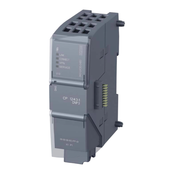
Preface Validity of this manual This document contains information on the following telecontrol products: ● CP 1243-1 DNP3 Article number6GK7 243-1JX30-0XE0 Hardware product version 1 Firmware version V1.1 The CP 1243-1 DNP3 is the communications processor for connecting SIMATIC S7-1200 to control centers using the DNP3 protocol. - Page 4 Preface The CP 1243-1 IEC has the same outer design as the CP 1243-1 DNP3 apart from the inscriptions for the product name, article number, firmware version and possibly hardware product version. At the top right behind the hinged cover of the module housing, you will see the hardware product version printed as a placeholder "X"...
- Page 5 This manual replaces the manual release 07/2013. Current manual release on the Internet You will also find the current version of this manual on the Internet pages of Siemens Industry Online Support in the directory of the relevant CP. This is located below the directory with the following entry ID: 16514597 (http://support.automation.siemens.com/WW/view/en/16514597)
- Page 6 ● DOC_OSS-CP1243-1DNP3-IEC_76.pdf Security information Siemens provides automation and drive products with industrial security functions that support the secure operation of plants or machines. They are an important component in a holistic industrial security concept. With this in mind, our products undergo continuous development.
-
Page 7: Table Of Contents
Table of contents Preface ..............................3 Application and properties ........................9 Communications services ......................9 Other services and properties ...................... 10 Configuration limits and performance data .................. 12 DNP3 device profile ........................13 Configuration examples ....................... 14 1.5.1 Configuration with 1 subnet ......................14 1.5.2 Configuration with connections over the Internet ................. - Page 8 Table of contents Notes on configuring individual functions ..................42 5.8.1 Communication types and SNMP ....................42 5.8.2 Ethernet interface (X1) > Advanced options ................43 5.8.3 Partner stations ........................... 46 5.8.4 Partner stations > Security options (DNP3) ................48 5.8.5 Communication with the CPU .....................
-
Page 9: Application And Properties
Application and properties Communications services Communications services The following communications services are supported: DNP3-CP ● DNP3 protocol Communication is based on the DNP3 SPECIFICATION Version 2.x (2007/2009). The CP is a communications processor of the SIMATIC S7-1200 for system connection to control centers using the DNP3 protocol for telecontrol applications. -
Page 10: Other Services And Properties
Application and properties 1.2 Other services and properties Table 1- 1 DNP3: Byte assignment of the status byte for DNP3 data points Flag name LOCAL_- DISCONTI- OVER_- RESTART ONLINE FORCED NUITY RANGE Meaning Local Counted Value Value not Value is operator value range... - Page 11 Application and properties 1.2 Other services and properties ● IP configuration - IPv4 and IPv6 The essential features of IP configuration for the CP: – The CP supports IP addresses according to IPv4 and IPv6. – An IPv6 address can be used in addition to an IPv4 address. –...
-
Page 12: Configuration Limits And Performance Data
Application and properties 1.3 Configuration limits and performance data ● Online functions From an engineering station (ES) on which STEP 7 is installed, you can use the online functions of STEP 7 via the CP to access the S7-1200 CPU if the station is located in the same IP subnet. -
Page 13: Dnp3 Device Profile
CP in the DNP3 device profile. You will find the DNP3 device profile of the CP 1243-1 DNP3 on the Internet pages of Siemens Industry Online Support under the following entry ID: 82856876 (http://support.automation.siemens.com/WW/view/en/82856876) CP 1243-1 DNP3, CP 1243-1 IEC... -
Page 14: Configuration Examples
Application and properties 1.5 Configuration examples Configuration examples 1.5.1 Configuration with 1 subnet Configuration example with a non-redundant control center The following example describes a configuration with a non-redundant control center in which all nodes are located in 1 IP subnet. In this example, the DNP3 protocol is used;... - Page 15 Application and properties 1.5 Configuration examples A configuration in which the IEC protocol is used would have the same setup apart from the CP type (here CP 1243-1 IEC). The S7-1200 stations are connected to the Internet via the CP and connected to the control center.
-
Page 16: Configuration With A Redundant Control Center
Application and properties 1.5 Configuration examples Addressing Refer to the information in the section Addressing and network configuration (Page 31). 1.5.3 Configuration with a redundant control center Configuration example with a redundant control center The following example contains a configuration with a redundant control center and connections via the Internet. -
Page 17: Requirements For Use
Requirements for use Hardware requirements The following setups do not take into account rails, housing, cabling and other accessories. Depending on the configuration of your plant, you require the following devices and firmware versions. Application example: Project with 1 subnet The following setup assumes that the master and stations are located in 1 IP subnet, see also the section Configuration with 1 subnet (Page 14). -
Page 18: Software Requirements
Requirements for use 2.2 Software requirements ● IEC – IEC CP – CPU with firmware version V3.0 or V4.0 – DSL router + SCALANCE S See also the reference in the section "Notes on the DSL router" below. In the master station: ●... -
Page 19: Leds And Connectors
LEDs and connectors Opening the covers of the housing Location of the display elements and the electrical connectors The LEDs for the detailed display of the module statuses are located behind the upper cover of the module housing. The Ethernet connector is located behind the lower hinged cover of the module. Opening the covers of the housing Open the upper or lower cover of the housing by pulling it down or up as shown by the arrows in the illustration. -
Page 20: Leds
LEDs and connectors 3.2 LEDs LEDs LEDs of the module The module has various LEDs for displaying the status: ● LED on the front panel The "DIAG" LED that is always visible shows the basic statuses of the module. ● LEDs below the upper cover of the housing The LEDs below the upper cover provide more detailed information on the module status. - Page 21 LEDs and connectors 3.2 LEDs Display of the basic statuses of the CP ("DIAG" LED) Table 3- 4 Display of the basic statuses of the CP DIAG Meaning (red / green) (if more than one point listed: alternative meaning) Basic statuses of the CP Power OFF •...
- Page 22 LEDs and connectors 3.3 Electrical connections DIAG LINK CONNECT SERVICE Meaning (red / green) (green) (green) (green) (green) (if more than one point listed: alternative meaning) Missing STEP 7 project data flashing red Backplane bus error flashing red Connection to Industrial Ethernet Connection to Industrial Ethernet exists Connection to Industrial Ethernet being •...
-
Page 23: Electrical Connections
LEDs and connectors 3.3 Electrical connections Electrical connections 3.3.1 Power supply Power supply The CM is supplied with power from the backplane bus. It does not require a separate power supply. 3.3.2 Ethernet interface X1P1 Ethernet interface The Ethernet connector is located behind the lower hinged cover of the module. The interface is an RJ-45 jack according to IEEE 802.3. - Page 24 LEDs and connectors 3.3 Electrical connections CP 1243-1 DNP3, CP 1243-1 IEC Operating Instructions, 02/2014, C79000-G8976-C312-02...
-
Page 25: Installation, Connecting Up, Commissioning
Installation, connecting up, commissioning Important notes on using the device Safety notices on the use of the device Note the following safety notices when setting up and operating the device and during all associated work such as installation, connecting up or replacing the device. Overvoltage protection NOTICE Protection of the external power supply... -
Page 26: Notices Regarding Use In Hazardous Areas According To Atex
Installation, connecting up, commissioning 4.1 Important notes on using the device WARNING EXPLOSION HAZARD DO NOT CONNECT OR DISCONNECT EQUIPMENT WHEN A FLAMMABLE OR COMBUSTIBLE ATMOSPHERE IS PRESENT. WARNING EXPLOSION HAZARD SUBSTITUTION OF COMPONENTS MAY IMPAIR SUITABILITY FOR CLASS I, DIVISION 2 OR ZONE 2. -
Page 27: Notices Regarding Use In Hazardous Areas According To Ul Hazloc
Installation, connecting up, commissioning 4.2 Installation 4.1.3 Notices regarding use in hazardous areas according to UL HazLoc WARNING EXPLOSION HAZARD DO NOT DISCONNECT WHILE CIRCUIT IS LIVE UNLESS AREA IS KNOWN TO BE NON-HAZARDOUS. This equipment is suitable for use in Class I, Division 2, Groups A, B, C and D or non- hazardous locations only. - Page 28 Installation, connecting up, commissioning 4.2 Installation Dimensions for installation Figure 4-1 Dimensions for installation of the S7-1200 Table 4- 1 Dimensions for installation (mm) S7-1200 devices Width A Width B * CPU (examples) CPU 1211C, CPU 1212C 90 mm 45 mm CPU 1214C 110 mm 55 mm...
-
Page 29: Installing, Connecting Up And Commissioning
Installation, connecting up, commissioning 4.3 Installing, connecting up and commissioning Installation location NOTICE Installation location The module must be installed so that its upper and lower ventilation slits are not covered, allowing adequate ventilation. Above and below the device, there must be a clearance of 25 mm to allow air to circulate and prevent overheating. - Page 30 Installation, connecting up, commissioning 4.3 Installing, connecting up and commissioning Table 4- 2 Procedure for installation and connecting up Step What to do Notes and explanations Mount the CP on the DIN rail and connect it to Use a 35 mm DIN rail. the module to its right.
-
Page 31: Configuration And Operation
Configuration and operation Note on operation NOTICE Closing the front panels To ensure interference-free operation, keep the front panels of the module closed during operation. Addressing and network configuration To configure and commission the CP, the following information is required: Address information of the master The following information is required for the STEP 7 configuration of the CP: ●... -
Page 32: Configuration In Step 7
Configuration and operation 5.3 Configuration in STEP 7 ● You configure the master IP address as normal. ● When configuring the CP interface, configure the IP address of the SCALANCE S as a router address. ● You create the VPN configurations with SCALANCE S both for the station end and for the control center end in STEP 7. -
Page 33: Configuring Datapoints And Messages (E-Mails)
Configuration and operation 5.4 Configuring datapoints and messages (e-mails) Requirement for configuring the communication One requirement for configuring communication between CP and control center is the programming of the assigned CPU and the input and output data of the station. PLC tags must also be created to assign the user data to the data points. - Page 34 Configuration and operation 5.4 Configuring datapoints and messages (e-mails) Data received from the communications partner is written by the CP to the CPU via the PLC tags or DBs. Configuring data points and messages in STEP 7 You configure the data points in STEP 7 in the Data point and alarm configuration. You can find this using the project tree: Project >...
-
Page 35: Datapoint Types
Configuration and operation 5.5 Datapoint types Datapoint types During the configuration of the user data to be transferred by the CP, each data point is assigned a protocol-specific data point type. The data point types supported by the CP along with the compatible S7 data types are listed below. - Page 36 Configuration and operation 5.5 Datapoint types Format (memory Data point type DNP3 object group Direction S7 data types Address area requirements) [variations] Floating-point number Analog Input 30 [6] LREAL Q, M, DB (64 bits) Analog Input Event 32 [6, 8] LREAL Q, M, DB Analog Output...
- Page 37 Configuration and operation 5.5 Datapoint types To allow the value resulting from local events or interventions to be transferred to the master, the data point in question requires a channel for mirroring back. This mirroring back function is enabled using the "Value monitoring (Reporting Changes)" option in the STEP 7 configuration, refer to the section "General"...
-
Page 38: Cpu Scan Cycle
Configuration and operation 5.6 CPU scan cycle Format (memory Data point type IEC type Direction S7 data types Address area requirements) Floating-point Measured value, short floating point <13> REAL Q, M, DB number (32 bits) number Measured value, short floating point <36>... -
Page 39: Types Of Transmission, Event Classes, Triggers
Configuration and operation 5.7 Types of transmission, event classes, triggers ● Low-priority read jobs - proportion For data points of the type "Input", which are configured with the "Low priority" setting in the data point configuration in "General > Priority in the scan cycle", the values of a part of the PLC tags are read in every scan cycle. - Page 40 Configuration and operation 5.7 Types of transmission, event classes, triggers The send buffer The send buffer is the data buffer on the CP for storing the values of events. The send buffer has a maximum size of 64000 events. The configured number of events is divided equally among all configured and enabled communications partners.
- Page 41 Configuration and operation 5.7 Types of transmission, event classes, triggers Event classes for the IEC protocol The process data of the various event classes is handled as follows: ● Every value triggered Each value change is entered in the send buffer in chronological order. ●...
-
Page 42: Notes On Configuring Individual Functions
Configuration and operation 5.8 Notes on configuring individual functions Notes on configuring individual functions Below, you will find information on the configuration of individual functions grouped according to parameter groups in STEP 7. Note Information in STEP 7 and in the manual If there are discrepancies between the following descriptions and the information in STEP 7 / Professional V13, the information in this document is valid. -
Page 43: Ethernet Interface (X1) > Advanced Options
Configuration and operation 5.8 Notes on configuring individual functions Range of performance of the CP as an SNMP agent The CP supports data queries using SNMP in version V1. For the CP to support the object groups of the standard MIB-II: ●... - Page 44 Configuration and operation 5.8 Notes on configuring individual functions Ethernet interface (X1) > Advanced options > Transfer settings Transmission settings – DNP3 ● Buffer for class 1 / 2 / 3 events Here, for each of the three event classes you specify the number of events after which the stored events are sent to the communications partner.
- Page 45 Configuration and operation 5.8 Notes on configuring individual functions ● Monitoring time for S and U frames (t Monitoring time for the acknowledgment of data frames of the master by the IEC CP. After receiving data from the master, the CP acknowledges the received data as follows: –...
-
Page 46: Partner Stations
Configuration and operation 5.8 Notes on configuring individual functions 5.8.3 Partner stations Partner stations > "Partner 'X'" ● Partner number The partner number is assigned by the system automatically and is used not to identify only the master address but also the communications partner. The partner number is required during configuration of the datapoints to assign the datapoints to a communications partner. - Page 47 Configuration and operation 5.8 Notes on configuring individual functions ● Report partner status If the "Report partner status" function is enabled, the CP signals the status of the communication to the remote partner. – Bit 0 of "PLC tag for partner status" (data type WORD) is set to 1 if the partner can be reached.
-
Page 48: Partner Stations > Security Options (Dnp3)
Configuration and operation 5.8 Notes on configuring individual functions 5.8.4 Partner stations > Security options (DNP3) Partner stations > Partner 'X' > "Security options" (DNP3 CP only) Preliminary remarks: Authentication and key exchange If the security function is enabled, the DNP3 master and station (DNP3 CP) authenticate themselves with a secret key, the pre-shared key. -
Page 49: Communication With The Cpu
Configuration and operation 5.8 Notes on configuring individual functions ● Authentication timeout Maximum waiting time for the response from the master to an authentication request of the DNP3 CP. Exceeding the wait time is evaluated as an error by the DNP3 CP. In this case, the DNP3 CP generates a security event and sends this to the master. -
Page 50: Data Point Configuration
Configuration and operation 5.8 Notes on configuring individual functions 5.8.6 Data point configuration 5.8.6.1 "General" parameter group "General" parameter group ● Value monitoring (Reporting Changes) (DNP3 CP only) The option is available with the following data point types. The option must be enabled if the data points are to be configured as an Output Event with mirroring back. -
Page 51: Analog Value Preprocessing" Parameter Group
Configuration and operation 5.8 Notes on configuring individual functions Sequence of analog value processing 1. Reading the data from the input area of the CPU 2. Analog value preprocessing (part 1) Processing involves the following steps: – Mean value generation - Mean value generation configured: Calculation and then continued at point 4. - Page 52 Configuration and operation 5.8 Notes on configuring individual functions Exception: The value -32768 / 8000 as fault ID for wire break of live zero hardware analog inputs is transferred. With a software input, on the other hand, all values lower than zero are corrected to zero.
- Page 53 Configuration and operation 5.8 Notes on configuring individual functions Mean value generation With this parameter, acquired analog values are transferred as mean values. The current values of an analog data point are acquired cyclically and totaled. The number of acquired values per time unit depends on the read cycle of the CPU and the CPU scan cycle of the CP.
-
Page 54: Threshold Value Trigger
Configuration and operation 5.8 Notes on configuring individual functions Note Evaluation of the value even when the option is disabled If you enable one or both options and configure a value and then disable the option later, the grayed out value is nevertheless evaluated. To disable the two options, delete the previously configured values "Start of measuring range"... -
Page 55: Configuring Messages
Configuration and operation 5.8 Notes on configuring individual functions Table 5- 4 Example of the integration calculation of a threshold value configured with 2.0 Time [s] Process value Current process Absolute deviation Integrated stored in the send value from the stored deviation (calculation buffer... - Page 56 Configuration and operation 5.8 Notes on configuring individual functions Requirements and necessary information Remember the following requirements in the CP configuration for the transfer of e-mails: ● It is necessary to enable the CP-specific type of communication: – DNP3: "Enable DNP3 protocol" –...
- Page 57 Configuration and operation 5.8 Notes on configuring individual functions Status Meaning 8405 The SMTP server has denied the login request. 8406 An internal SSL error or a problem with the structure of the certificate was detected by the SMTP client. 8407 Request to use SSL was denied.
- Page 58 Configuration and operation 5.8 Notes on configuring individual functions Status Meaning 8550 SMTP server cannot be reached. You have no access rights. Check the following configuration data: CP configuration > E-mail configuration: • – User name – Password – Email address (sender) Alarm configuration >...
-
Page 59: Diagnostics And Upkeep
New firmware versions of the CP If a new firmware version is available for the module, you will find this on the Internet pages of Siemens Industry Online Support under the following ID: 68853485 (http://support.automation.siemens.com/WW/view/en/68853485) CP 1243-1 DNP3, CP 1243-1 IEC... - Page 60 Diagnostics and upkeep 6.2 Downloading firmware On the Internet page, select the "Entry list" tab and the "Download" entry type. You will find the firmware file and a description of the procedure there. Downloading the firmware via the Web server of the CPU Follow the steps below to connect to the Web server of the CPU and to download the CP's new firmware file to the station.
- Page 61 Diagnostics and upkeep 6.2 Downloading firmware 5. Download the certificate to your PC by clicking the "Install certificate ..." button. The certificate is loaded on your PC. You will find information on downloading a certificate in the help of your Web browser and in the STEP 7 information system under the key words "HTTPS"...
-
Page 62: Module Replacement
Diagnostics and upkeep 6.3 Module replacement Module replacement Module replacement CAUTION Read the system manual "S7-1200 Programmable Controller" Prior to installation, connecting up and commissioning, read the relevant sections in the system manual "S7-1200 Programmable Controller" (refer to the documentation in the Appendix). -
Page 63: Technical Specifications
Technical specifications Table 7- 1 Technical specifications of CP 1243-1 DNP3 and the CP 1243-1 IEC Technical specifications Article numbers CP 1243-1 DNP3 6GK7 243-1JX30-0XE0 • • CP 1243-1 IEC 6GK7 243-1PX30-0XE0 • • Attachment to Industrial Ethernet Quantity Design RJ-45 jack Properties 100BASE-TX, IEEE 802.3-2005, half duplex/full duplex, autocrossover,... - Page 64 Technical specifications Technical specifications Design, dimensions and weight Module format Compact module for S7-1200, single width Degree of protection IP20 Weight 122 g Dimensions (W x H x D) 30 x 110 x 75 mm Installation options Standard DIN rail Switch panel Product functions ** * For details, refer to the IK PI catalog, cabling technology...
-
Page 65: Approvals
SIMATIC NET products are regularly submitted to the relevant authorities and approval centers for approvals relating to specific markets and applications. You will also find the current approvals for the product on the Internet pages of Siemens Automation Customer Support under the following entry ID: 68853485 (http://support.automation.siemens.com/WW/view/en/68853485) - Page 66 D-90327 Nürnberg Germany You will find the EC Declaration of Conformity for this product on the Internet at the following address: 68853485 (http://support.automation.siemens.com/WW/view/en/68853485) → tab "Entry list" Filter settings: Entry type: "Certificates" Certificate Type: "Declaration of Conformity" Search items(s): <name of the module>...
- Page 67 Approvals WARNING Installation guidelines The product meets the requirements if you keep to the following during installation and operation: • The notes in the section Important notes on using the device (Page 25) • The installation instructions in the document /1/ (Page 71) Over and above this, the following conditions must be met for the safe deployment of the CP: ●...
- Page 68 Approvals CP 1243-1 DNP3, CP 1243-1 IEC Operating Instructions, 02/2014, C79000-G8976-C312-02...
-
Page 69: Dimension Drawings
Dimension drawings Note All dimensions in the drawings are in millimeters. Figure B-1 CP 1243-1 DNP3 / CP 1243-1 IEC: Front view and side view left CP 1243-1 DNP3, CP 1243-1 IEC Operating Instructions, 02/2014, C79000-G8976-C312-02... - Page 70 Dimension drawings Figure B-2 CP 1243-1 DNP3 / CP 1243-1 IEC: View from above CP 1243-1 DNP3, CP 1243-1 IEC Operating Instructions, 02/2014, C79000-G8976-C312-02...
-
Page 71: Documentation References
Documentation references Where to find Siemens documentation ● You will find the order numbers for the Siemens products of relevance here in the following catalogs: – SIMATIC NET Industrial Communication / Industrial Identification, catalog IK PI – SIMATIC Products for Totally Integrated Automation and Micro Automation, catalog... - Page 72 Documentation references SIMATIC NET CP 1243-1 DNP3, CP 1243-1 IEC Operating Instructions Siemens AG entry ID: 69270828 (http://support.automation.siemens.com/WW/view/en/69270828) CP 1243-1 DNP3, CP 1243-1 IEC Operating Instructions, 02/2014, C79000-G8976-C312-02...
-
Page 73: Index
Index Abbreviations/acronyms, 4 Glossary, 5 Addressing - redundant master, 32 Analog value preprocessing, 51 Article number, 3 Hardware product version, 3 Communication, configuration, 33 Configuring communication, 33 IEC 60870-5, 3 Connection resources, 12 IEC addressing, 31 Image memory, 39 Internet connections, 31 IP address (master), 31 Data buffering, 13 IP address master (redundant), 32... - Page 74 Index Replacing a module, 62 Reporting changes, 36, 50 Reset trigger bit, 41, 56 S7 connections Enable, 42 Resources, 12 S7 data types, 33 Safety notices, 25 Security events, 10 Security options (DNP3), 48 Send buffer, 13, 40 Service & Support, 6 SIMATIC NET glossary, 5 SNMP, 12 Specifications, 9...