Table of Contents
Advertisement
Advertisement
Table of Contents

Related Manuals for Panasonic WR-201E


Summary of Contents for Panasonic WR-201E
- Page 1 Power Amplifier & Mixer Integrated System DESIGN HANDBOOK...
- Page 2 (240W) Mixing Power Amplifier WA-MA120N (120W) Sound Message Unit WU-ZM001E TABLE Surveillance Unit WU-ZS001E CONTENTS Remote Microphone WR-201E Remote Control Microphone WR-210AE Concept P4 ~ P7 System Examples P8 ~ P15 Connections P16 ~ P43 Products P44 ~ P73 Block Diagrams...
- Page 3 30 zones. Energy Saving Design NO.1 (Master) This mixing power amplifier uses Class-H amplifier technology developed by RAMSA, the Panasonic Professional Audio Group, to minimize power consumption. NO.2 (Slave) NO.10 (Slave) WR-210AE...
- Page 4 CONCEPT BASIC SYSTEM DIAGRAM Mixing Power Amplifier (WA-MA120N/240N) Connection Schematic diagram of Remote Microphone with Extension Unit (WU-RM205E) connected for announcements on 15 channels. The illustration in the broken line frame shows how to connect more than one Remote Microphones to Mixing Power Amplifier. Refer to this illustration for method of connecting up to 4 Remote Microphones.
- Page 5 SYSTEM EXAMPLES DEPARTMENT STORE Department Store Outline KEY POINT • Remote-controlled Microphone Connection Allows remote microphones to be used for individual, group, all- at-once emergency, and simultaneous 2-channel broadcasts. • Cascade Connection Allows added amplifier capacity and additional speaker circuits. •...
- Page 6 SYSTEM EXAMPLES RESIDENCE Residence Outline KEY POINT • Remote-controlled Microphone Connection Allows remote microphones to be used for individual, group, all- at-once emergency, and simultaneous 2-channel broadcasts. • Additional Amplifier Connection When additional capacity is needed. • Other Features A chime is built into the main amplifier unit. The optional Sound Message Unit supports configuration of systems for regular broadcasts or simple emergency announcements.
- Page 7 SYSTEM EXAMPLES SHOPPING CENTER Shopping Center Outline KEY POINT • Remote-controlled Microphone Connection Allows remote microphones to be used for individual, group, all- at-once emergency, and simultaneous 2-channel broadcasts. • Cascade Connection Allows added amplifier capacity and additional speaker circuits. •...
- Page 8 SYSTEM EXAMPLES COMPOUND BUILDING Compoumd Building Outline KEY POINT Public Address Paging System for whole facility • 2-channel Broadcast Transmit a message only to the zone that needs it. • Cascade Connection Allows added amplifier capacity and additional speaker units. •...
- Page 9 Note the following precautions when using an external battery. • Make sure the external battery is a 24 V Lead Acid battery (or two 12 V batteries in series connection). Panasonic Corporation holds no responsibility for any Amplifier fault operation or other inconveniences resulting from using any other batteries except that indicated above.
- Page 10 CONNECTIONS WA-MA120N/WA-MA240N LINE1,2, INPUT2,3, REC OUT, INS IN/OUT Connections • Use the connections shown below for a microphone or recording/playback equipment, effect device that is not equipped with activation control (no-voltage make contact). • For information about connecting INPUT1, refer to page 19. WA-MA120N WA-MA240N Microphone, etc.
-
Page 11: Speaker Connection
CONNECTIONS WA-MA120N/WA-MA240N Remote Microphone (WR-210AE) Connection • Up to four Remote Microphone units can be connected. For multiple connections, priority connection between Remote Microphones is required. For more information, consult the operating instructions of the Remote Microphone. WA-MA120N WA-MA240N Important 1 LINE OUT H CONT LINE OUT C... - Page 12 CONNECTIONS WA-MA120N/WA-MA240N Connecting to Override External Attenuation during All-zone Announcement (Using 3-wire connection) WA-MA120N WA-MA240N Amplifier ATT OVERRIDE IN B All-zone announcement ON IN A DIRECT OUT ZONE 1 ZONE 2 ZONE 3 Connecting to Override External Attenuation during All-zone Announcement (Using 4-wire connection) WA-MA120N WA-MA240N...
- Page 13 Battery Connection • Make sure the external battery is a 24 V Lead Acid battery (or two 12 V batteries in series connection). Panasonic Corporation holds no responsibility for any Amplifier fault operation or other inconveniences resulting from using any other batteries except that indicated above.
- Page 14 CONNECTIONS WA-MA120N/WA-MA240N Inter-area All-zone Announcement Connection • When Amplifiers are being used for separate operation in multiple areas, they can be connected using the ALL CALL BUS to allow all-zone announcement from one area to all of the other areas. •...
- Page 15 CONNECTIONS WA-BA240N Line-level Equipment Connection • Connect external devices (e.g. pre-amplifiers) to the LINE IN jack. The following illustration is a connection example with the Mixing Power Amplifier (WA-MA120N or WA-MA240N). • Be sure to use the gold plated plugs (accessories) when using the LINE IN jack and/or the LINE THRU jack. WA-MA120N WA-MA240N Important...
- Page 16 Battery Connection • Make sure the external battery is a 24 V Lead Acid battery (or two 12 V batteries in series connection). Panasonic Corporation Amplifier fault operation or other inconveniences resulting from using any other batteries except that indicated above.
-
Page 17: Connections And Settings
CONNECTIONS WU-ZM001E CONNECTIONS AND SETTINGS Warning: • Be sure to turn off power before connecting or configuring settings. Be sure to turn off the device supplying power to the Sound Message Unit. Leaving power supplied creates the risk of electric shock and damage to equipment. Installing the Sound Message Unit to the mixing power amplifier and configuring connections 1. - Page 18 CONNECTIONS WU-ZS001E SURVEILLANCE I/F Connector Example Application: (1) – Switch Trigger/Status Indication After connecting to an external line as shown below, the switches can be used to trigger various operations, while indicators can be used to determine the status of the amplifier. SURVEILLANCE I/F Connector CLOCK ADJ CONT SP LINE REFERENCE...
- Page 19 CONNECTIONS WR-210AE CONNECTIONS Connectable PA Systems Refer to the following table to determine the number of Remote Microphones that can be connected to the PA systems. PA System Name Number of devices that can be connected Name Type Remote Microphone (WR-210AE) Mixing Power Amplifier WA-MA120N WA-MA240N...
- Page 20 CONNECTIONS WR-210AE Individual Priority Making connection settings Refer to the following illustration for connecting up to 4 Remote Microphone. And the priority order of Remote Microphones depends on the order, in which they are connected to the Mixing Power Amplifier. Connect the high priority Remote Microphone’s priority output to the low priority Remote Microphone’s priority input.
- Page 21 Refer to the following table to determine the number of Remote Microphones that can be connected to the PA systems. PA System Name Number of Possible Connections Name Type Remote Microphone (WR-201E) Mixing Power Amplifier WA-MA120N WA-MA240N Cable Diameters Cable Lengths...
- Page 22 43.) Important: • Set the call sign volume-control on the bottom of the Remote Microphone (WR-201E) to its lowest setting to use the Mixing Power Amplifier's built-in call sign. *1 When using more than one Remote Microphone (WR-201E) to make announcements to each block, a reverse current inhibitor diode (forward current 1 A or greater, peak inverse voltage 200 V or greater) is necessary.
- Page 23 W model (WA-MA240N) to suit the structure of your system. and more. Features such as 2-channel announcement, Remote The term "Amplifier" in this manual refers to the Panasonic Microphone announcement, zone expansion capabilities, WA-MA120N/240N Mixing Power Amplifier. FEATURES •...
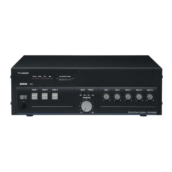
- Page 24 PRODUCTS WA-MA120N/WA-MA240N MAJOR OPERATING CONTROLS & TERMINALS Front View * The illustration shows the WA-MA120N. The WA-MA240N is the same in both appearance and function. Rear View DIMENSIONS ACCESSORIES Operating Instructions (this manual) ...1 pc. Use the following items for installation work. Power Cords (1.8 m)...2 pcs.
-
Page 25: Specifications
PRODUCTS WA-MA120N/WA-MA240N SPECIFICATIONS Model No. WA-MA120N Power Source AC:110 V-120 V or 220 V-240 V (selectable), 50 Hz /60 Hz DC:+24 V (Battery), M3 screw terminal Power Consumption (AC) Non-operation mode (standby) Under normal operating conditions according to IEC60065 With rated output signal Current Consumption (DC) Non-operation mode (standby) Under normal operating... - Page 26 Those who want to expand their high-impedance loudspeakers but feel that the output of their main power The term "Amplifier" in this manual refers to the Panasonic amplifier is insufficient can increase the output of their main WA-BA240N Booster Power Amplifier.
- Page 27 PRODUCTS WA-BA240N ADJUSTING INPUT VOLUME 100 V OUT Power Amplifier (WA-MA120N, MA240N, etc.) for High-Impedance Loudspeakers Pre-amplifier, etc LINE OUT Line-level equipment, etc. • When line-level equipment is connected to LINE IN, use the LEVEL knob on the back of the Amplifier to adjust the volume to the desired level.
- Page 28 • SD memory cards with the following capacity (8 MB to 2 GB) can be used on this unit. (Panasonic cards are recommended.) 8 MB, 16 MB, 32 MB, 64 MB, 128 MB, 256 MB, 512 MB, 1 GB and 2 GB •...
-
Page 29: Connecting External Equipment
PRODUCTS WU-ZM001E MAJOR OPERATING CONTROLS & TERMINALS Front View Rear View RECORDING METHODS Notes on recording • Sound data is recorded to the SD memory card. Do not remove the SD memory card during recording. • You can switch the time display between elapsed recorded time and remaining recording time by pressing the SCHEDULE switch while recording. - Page 30 PRODUCTS WU-ZM001E CONFIGURATION OF MENU SCREEN • Use the SELECT dial to move between screens on the same level. Normal operation • Use the ENTER switch and the CANCEL Use MENU switch to go to setting screen switch to move between different levels. Time setting screen Recording screen Monitoring screen...
- Page 31 Volume adjustment REC IN knob [REC IN] PHONES knob [PHONES] OUTPUT knob [OUTPUT] Storage media SD memory card (Panasonic cards are recommended) *Up to a maximum of 2 GB Audio signal format Playback WAV format: 44.1 kHz, 16 bit, MONO MP3 format: 44.1 kHz, 128 kbps, STEREO...
- Page 32 PRODUCTS WU-ZS001E Surveillance Unit WU-ZS001E PREFACE This Surveillance Unit is intended for installation on the WA- abnormally high temperatures, and notifies when MA120N/240N Mixing Power Amplifier (sold separately). abnormalities are discovered. Installation of the Surveillance Unit ensures system reliability • Speaker line failure detection can be executed by Sound and safety by detection of speaker line failures, as well as Message Unit scheduler.
- Page 33 PRODUCTS WU-ZS001E MAJOR OPERATING CONTROLS & TERMINALS Front of Unit SURVEILLANCE I/F SP LINE SP LINE FAULT CHECK SETTING /SETTING STATUS AMBER-NO SETTING RED-SHORT GREEN-SETTING COMPLETED AMBER-OPEN RM DC /DC OUT VOLTAGE POWER T1AL SELECTOR 1 SURVEILLANCE I/F Connector 2 CHECK/SETTING Switch 3 SETTING STATUS Indicator 4 SP LINE FAULT ZONE 1-5 Indicators 5 SP LINE FAULT GROUND FAULT Indicator...
- Page 34 PRODUCTS WU-ZS001E Front of Mixing Power Amplifier 6 FAULT Indicator [FAULT] When this Surveillance Unit is installed, this indicator lights upon detection of a fault. • Speaker system abnormality (short, grounding, disconnection) • Power amplifier fault (voice system fault, abnormally high temperature) Flashes when checking or acquiring reference value for speaker line.
- Page 35 PRODUCTS WR-210AE Remote Control Microphone WR-210AE PREFACE This Remote Microphone is designed for use with public • The priority function allows you to set the order of priority address (PA) systems. It supports both separate zone between Remote Microphones if more than one Remote announcement and all-zone announcement capabilities.
- Page 36 PRODUCTS WR-210AE SPECIFICATIONS General Power Supply 24 V DC, 45 mA or less (connection terminal) Ambient Temperature 0 °C - +45 °C Dimensions 250 (W) mm x 55 (H) mm x 155 (D) mm (excluding projections and flexible microphone) Weight Approx.
- Page 37 PRODUCTS WR-201E Remote Microphone WR-201E PREFACE This single-channel Remote Microphone is designed for use with public address (PA) systems. • A LINE IN terminal is available to connect an external sound source such as a CD player or background music (BGM) device.
- Page 38 BLOCK DIAGRAMS BLOCK DIAGRAMS SYSTEM WA-MA120N/WA-MA240N...
- Page 39 BLOCK DIAGRAMS WA-BA240N WU-ZM001E/WU-ZS001E WU-ZM001E Sirial IO I/F between the Amplifier Digital Tr Parallel IO Digital Tr CODEC Input MUTE ( Tr ) Phones Output Announce Message Output Message P_FAIL Output SENSE DC24V 12 Reg 5V Reg 3.3V Reg 5V Reg Main Board WU-ZS001E Audio announcement...
- Page 40 BLOCK DIAGRAMS WR-210AE/WU-RM205E FLEXIBLE WR-210AE Modular Jack Modular Jack WU-RM205E Modular Jack VOL CONT BLOCK DIAGRAMS WR-201E...
- Page 41 When choosing speakers, it is important to consider the strucutre or wood quality of the building or the interior. As much as possible, Panasonic speakers have been designed to harmonize with a variety of interiors. Because building interiors tend to be predominantly white, we have used it as the standard underlying tone.