Panasonic WR-DA7 User Manual
Panasonic wr-da7 users guide
Hide thumbs
Also See for WR-DA7:
- User manual (308 pages) ,
- Service manual (86 pages) ,
- Application manual (63 pages)

Related Manuals for Panasonic WR-DA7


Summary of Contents for Panasonic WR-DA7
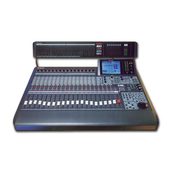
- Page 1 Users’ Guide Audio Mixer WR-DA7 The meter bridge shown in photo is one of the optional accessories. Before attempting to connect or operate this product, please read these instructions completely.
- Page 2 Warning: This equipment generates and uses radio frequency energy and if not installed and used properly, i.e., in strict accordance with the instruction manual, may cause harmful interference to radio communications. It has been tested and found to comply with the limits for a Class A computing device pursuant to Subpart J of Part 15 of FCC Rules, which are designed to provide reasonable protection against such interference when operated in a commercial environment.
- Page 3 If you lose the fuse cover the plug must not be used until a replacement cover is obtained. A replacement fuse cover can be purchased from your local Panasonic Dealer. IF THE FITTED MOULDED PLUG IS UNSUITABLE FOR THE SOCKET OUTLET IN YOUR HOME THEN THE FUSE SHOULD BE REMOVED AND THE PLUG CUT OFF AND DISPOSED OF SAFELY.
-
Page 4: Digital Mixer Wr-Da7
Digital Mixer WR-DA7 Users’ Guide Version 1.10 D A 7 U s e r s ’ G u i d e... - Page 5 Limit of Liability/Disclaimer of Warranty: The author, Audio Video Systems Division of Matsushita Communication Industrial Co., Ltd has used its best efforts in preparing this book. However, Audio/Video Systems Division of Matsushita Communication Industrial Co., Ltd makes no representation or warranties with respect to the accuracy or completeness of the contents of this book and hereby specifically disclaims any implied warranties or merchantability or fitness for any particular purpose and shall in no event be liable for any loss of profit or any other commercial damage, including but not limited...
-
Page 6: Table Of Contents
Digital Mixer WR-DA7 Users’ Guide Table of Contents 1. Introduction 1-1 A New Beginning 1-2 About This Manual 1-3 Making the DA7 Work For You 2. DA7 Tour 2-1 Overview 2-2 Top Panel 2-3 Display Bridge 2-4 Rear Panel 3. Quick Start... - Page 7 6. Fader Layers and Channel Strips 6-1 Fader Layers 6-2 Channel Strip 7. Equalizer 7-1 Overview 7-2 Equalizer Section 7-3 Equalizer Window 7-4 Equalizer Library Window 7-5 Equalizer Window, Multi-Channel View 8. Pan/Assign, Surround, Bus Assign 8-1 Pan/Bus Assign Controls 8-2 Surround Window 8-3 Surround Window, Multi-Channel View 9.
- Page 8 12. D-I/O (Digital Input/Output) 12-1 D-I/O, Input Set Window 12-2 D-I/O, To Slot Window 12-3 D-I/O, Dither Window 13. Group 13-1 Overview 13-2 FADER GRP (Fader Group) Window 13-3 MUTE GRP (Mute Group) Windows 13-4 LINK/STR (Stereo) Window 14. Automation 14-1 Automation, Setup Window 14-2 Automation, Execute Window 14-3 Automation, EVT EDIT (Event Edit) Window...
- Page 9 Appendixes Appendix A, Setup Scenarios Appendix B, LCD Screen Displays Appendix C, Abbreviations and Acronyms Appendix D, Default Settings Appendix E, Cables and Connections Appendix F, Technical Specifications Appendix G, MIDI Implementation Chart Glossary Index T a b l e o f C o n t e n t s D A 7 U s e r s ’...
-
Page 10: Introduction
Introduction 1-1 A New Beginning The Digital Mixer WR-DA7 sets a new standard for affordable automated digital audio mixing and production. The DA7 has a number of features built into it that until recently, were the privilege of only high-end production facilities. - Page 11 C h a p t e r 1 Functionality Let's take a moment to preview some of the main features and benefits of the DA7. Fader Layer controls permits you to mix and monitor the 32 inputs, the 6 aux sends and the 6 aux returns, the 8 buses, and the unique CUSTOM/MIDI layer.
- Page 12 C h a p t e r 1 Simplicity The DA7 is simple to operate, so you will spend less time as an engineer and more time as an artist. Engineered for ease of use, the Human-Machine Interface (HMI) provides a variety of ways to access and assign the channel parameters for your sources.
-
Page 13: About This Manual
1-2 About This Manual Document Notes The first three chapters of the DA7 Users’ Guide provide an introduction to the system and basic information for the system. Chapter 1, Introduction • general information about the Users’ Guide and the system used to produce the document •... - Page 14 Symbols and Conventions Used in this Guide The DA7 Users’ Guide uses the icons and conventions listed below. Whenever possible, the way something appears in the Users’ Guide is as it appears on the DA7. Numbers in a triangle indicate a sequential step in a process. Numbers in a circle indicate a list.
- Page 15 C h a p t e r 1 The term “area” refers to a window region in the LCD of the Display Bridge of the mixer. The term “section” refers to a region on either the Top Panel or the Rear Panel of the mixer.
-
Page 16: Making The Da7 Work For You
C h a p t e r 1 1-3 Making the DA7 Work For You Although the DA7 has some analog inputs, it should really be thought of as a digital mixer. Like most equipment, the DA7 comes set with factory defaults, some of which may or may not provide the kind of operational preferences you would like. - Page 17 MASTER RESET If you’ve already pushed as many buttons as possible after powering up the DA7 to see what it could do, or if you have accidentally changed any of the factory presets and cannot figure out what you have done, you need to know about the master reset command.
- Page 18 C h a p t e r 1 CONFIGURATION The [UTILITY>CONFIG] window can be accessed by pressing the UTILITY button on the Top Panel. This is where the [CONFIGURATION] selections are located. One of the features here is [AUTO CHANNEL SELECT]. When active, every time a fader is moved or a SELECT button is engaged, whatever window you are in will change to the [CHANNEL] window for that selected channel.
- Page 19 C h a p t e r 1 MONITOR SETUP To customize the monitor setup of the DA7, access the [SOLO/MON] window by pressing the SOLO MONITOR button on the Top Panel. UTILITY>SOLO/MON Window The [MON A] area function mutes the MONITOR A speakers 20dB. When selected, the button will appear in inverse video, and the speakers will remain dimmed until the...
- Page 20 C h a p t e r 1 For more information on these windows, see Chapter 16, Utility and Solo Monitor, page 16-2. To find out about the 5.1 surround sound monitor output, see page 16-3, and for more on the DA7s’ surround sound features, see Chapter 8, Pan/Assign, Surround, Bus Assign.
- Page 21 C h a p t e r 1 Or, if you prefer to use an external wordclock reference as the master wordclock, the external wordclock master must output a sample frequency that is common to all devices. When you are referencing the DA7 to video, you should be very careful to set the DA7 up properly.
-
Page 22: Da7 Tour
Chapter 2 DA7 Tour 2-1 Overview Your tour of the DA7 begins with a brief description of the Human-Machine Interface (HMI) design concept, and then an introduction to the elements, functions, and features of the DA7. You may ask, “what is a Human-Machine Interface (HMI)?”... - Page 23 C h a p t e r 2 Functions and features of the mixer are accessed via knobs, faders, and buttons on the Top Panel of the DA7. The LCD screen reflects any cursor controls adjustments and/or selections you make on the Top Panel. The and the JogDial are both used to navigate the current window displayed or to make adjustments to the data fields.
-
Page 24: Top Panel
2-2 Top Panel The illustrations on this page and the next depict the Top Panel of the DA7. The number assignments are reflected on the Top Panel cutaway view on page 2-4. Page 2-5, adjacent to the cutaway view, provides the explanation of the numbered sections of the Top Panel. - Page 25 Illustrated Guide Explanations of the numbered sections begins on the next page. MIC/LINE MIC/LINE INPUT INPUT PEAK / PEAK / SIGNAL SIGNAL MASTER DISPLAY EQUALIZER FADER FADER AUX 1 AUX 1 METER AUX 2 AUX 2 CHANNEL AUX 3 AUX 3 PAN/SURR PAN/SURR AUX 4...
-
Page 26: Aux Section Controls
Channel Strip – input gain controls with channel control and status indicators. Also called a Channel Fader Strip. AUTOMATION/AUX LED button – selects the display mode of the Channel Strip LED field indicators, and arms the AUTOMATION system. MASTER DISPLAY section – the METER and CHANNEL buttons are direct buttons to the respective LCD screen windows. - Page 27 Channel Fader Strip Channel numbers AUX/BUS Layer function Channel Fader Strip There are sixteen Channel Fader Strips on the DA7. The functionality of each Channel Fader Strip is determined by which of the four Fader Layer controls selected: INPUT 1-16, INPUT 17-32, AUX/BUS, and a user CUSTOM/MIDI function.
-
Page 28: Channel Strip
The SELECT LED button, when on (orange), identifies the channel as the current channel selected. Only one Fader Strip can be selected at a time (unless it’s in stereo or link mode). For more detail, see Chapter 5, Channel, Library, and Meter Windows. The ON LED button toggles on (red) and off. - Page 29 Pressing the METER button will display the [METER] window group on the LCD screen in the Display Bridge. Pressing the METER button again will cycle the three window selections: [METER INPUTS 1-32], [BUS/AUX], [SLOT]. Pressing the CHANNEL button will display the [CHANNEL] window group on the LCD screen in the Display Bridge.
- Page 30 PAN/ASSIGN/ PAN parameter knob or center surround sound attenuator PAN ON LED button MASTER L/R LED button DIRECT LED button PAN/ASSIGN/ Pan, bus assignment, and surround sound parameters for the selected channel is set within this area. The pan control is always active for the L/R bus, so you do not need to activate the ON button to pan across the Master L/R out.
- Page 31 DYNAMICS/DELAY Section THL (threshold), ATK(attack), DLY (delay) parameter knob or right surround sound attenuator RATIO, RLS (release), GAIN parameter knob or surround right surround sound attenuator DYNAMICS ON LED button DYNAMICS/DELAY Section DYNAMICS and/or DELAY processing can be added to each of the DA7 Channels.
- Page 32 AUX Section Send LEVEL volume and assign ON/OFF knob FADER CONTROL mode LED button This section of the Top Panel contains controls for routing selected channels from/to outboard sources. These six aux routes are independent of the channel input connectors on the Rear Panel of the DA7 and greatly expand the flexibility of the mixer.
-
Page 33: Display Bridge
Display Bridge LCD screen Display Bridge Section The Display Bridge contains the information for the current status of the DA7 and the LCD screen. The various windows for the functions and features of the mixer are displayed on the LCD screen. BUS Fader Strip Bus Assign numbers... - Page 34 The SOLO LED button toggles on (red) or off. When on, the selected bus output will be routed to the MONITOR A speakers and headphones, overriding the previous input. There are two bus numbers for each strip, indicating the BUS ASSIGN selections that can be controlled by the strip.
- Page 35 Fader Layer Controls Section INPUT 1-16 LED button (green) INPUT 17-32 LED button (red) AUX/BUS LED button (orange) CUSTOM/MIDI LED button (orange) Fader Layer Controls Section The Fader Layer controls significantly expand the flexibility of the DA7 mixer. The LED button selections define the current function for the fader strips.
-
Page 36: Monitor Section
MONITOR Section MONITOR A source selection buttons MONITOR A MONITOR A MONITOR B source selection buttons MONITOR B Talkback ON LED button TALK BACK The DA7 provides controls for two monitor outputs and a talkback circuit. There are source selection LED buttons for the MONITOR A and MONITOR B outputs, and LEVEL knobs for both of the monitor outputs and the talkback circuit. - Page 37 MONITOR B Controls The MONITOR B selection LED buttons route the input selected (green) to the MONITOR B OUTPUT (STUDIO) connections on the Rear Panel of the mixer. The selections are: MONITOR A routes the current MONITOR A selection to the studio monitors.
- Page 38 C h a p t e r 2 UTILITY Button Pressing the UTILITY button will display the [UTILITY] window group on the LCD screen in the Display Bridge. The window displayed will be determined by the window selection buttons at the bottom of the window. Pressing the UTILITY button again will cycle the window selections: [OSC_BATT], [CONFIGuration], [USER CuSToM].
-
Page 39: Library Section
SCENE MEMORY Section WRITE LED button SCENE MEMORY Section SCENE MEMORY allows you to store and recall complete mixer setups and functions. There are fifty registers, numbered 01 through 50, available for storage of mixer settings. Memory 00 is reserved for Automation. Press either the WRITE LED button or the READ LED button (orange) to select it and display the [ReaD/WriTe] window of the [SCENE MEMORY] window group on the LCD screen of the Display Bridge. - Page 40 There are three mixer functions with associated libraries: CHANNEL, EQUALIZER, DYNAMICS/DELAY. The library feature allows you to store and recall individual function parameters to a separate library. There are fifty registers for each library, numbered 01 through 50. The RECALL button opens the library window for the selected function. This means that if the [CHANNEL] window was displayed when you pressed the RECALL button, the CHANNEL library will be displayed.
-
Page 41: Lcd Screen
2-3 Display Bridge LCD screen Display Bridge Section The Display Bridge for the DA7 is your “window” to the mixer functions and features. There are seven elements comprising the Display Bridge: the LCD screen, the L/R meter display, the MEMORY numeric readout, the CONSOLE LOCK LED status indicator, the CONTRAST control knob, the MULTI-CH VIEW (multi-channel) LED button, the SOLO LED status indicator. - Page 42 The LCD screen is the 320x240 backlit liquid-crystal display (LCD) element of the Display Bridge. The screen displays the various windows that show the functions and status of the DA7. The windows contain areas and items that can be accessed with the cursor control or JogDial. There are three general areas for the windows displayed on the LCD screen: the [taskbar] area, the [function] area, the [windows selection buttons] area.
- Page 43 Timecode Field This field displays the most recent time code value received by the mixer, as defined by the settings in the [AUTOMATION>EXECUTE] window. SCENE Field This field displays the most recently read SCENE MEMORY number and name. Function Area The [function] area of a window contains the various controls, buttons, settings, and values for the current window.
- Page 44 C h a p t e r 2 SOLO LED Status Indicator SOLO SOLO LED Status Indicator Located below the L/R meter display, the SOLO LED status indicator will light and flash (red) when SOLO has been activated for any channel on the mixer.
- Page 45 C h a p t e r 2 CONTRAST Control Knob CONTRAST CONTRAST Control Knob This knob controls the contrast value of the LCD screen. Rotate the knob to adjust the contrast value of the LCD screen for optimum viewing and to suit the operating environment.
-
Page 46: Rear Panel
2-4 Rear Panel Everything that goes in, out, and through the DA7 happens on the Rear Panel, with the exception of the headphone connector. The DA7 provides multiple ways for doing many things, so let your creativity be your guide. The rear of the DA7 is configured in four rows. - Page 47 Rows 1 & 2 Connectors Inputs 1-8 (XLR). Use these for balanced Inputs 9-16 (TRS). Use these for balanced -60 to +10 signals -60 to +10 signals. Phantom powered Channel 1-16 Inserts. These are TRS send and return connectors. Cutaway of DA7 Rear Panel (Rows 1 and 2) Input and Insert Connectors Connectors in these two rows are numbered from right to left on the Rear Panel.
- Page 48 Row 3 Connectors Master L/R outputs Monitor B outputs (Analog XLR balanced) (Analog TRS balanced) Record L/R outputs Monitor A outputs (Analog TRS balanced) (Analog TRS balanced) Cutaway of DA7 Rear Panel (Row 3) Output Connectors AUX SEND 1/2 Use RCA connectors to attach a digital effects device or another S/PDIF device to the AUX SEND 1/2 and AUX RETURN 1/2 digital terminals.
- Page 49 Monitor B Out These terminals are 1/4” TRS dual phono plugs at a level of +4dB, 600 and connect the output of the MONITOR B source selection to an external amplifier for monitoring in the studio. [REC OUT] Record Output Use 1/4”...
- Page 50 C h a p t e r 2 Format Select Switch This switch is used to select the signal format of the Digital Record Output, either AES/EBU (RS-422/110Ω) or S/PDIF (0.5 V[p-p]/ 75Ω) physically. The status information included in the output signals is always “professional” regardless of the switch position.
- Page 51 Serial Port [RS-422/485] Use this serial port to connect an IBM compatible computer that has an RS- 422/485 port. Connect to the DA7 with a D-SUB 9-pin connector. Optional remote control software for your computer can be used to control the DA7, thus expanding the features and capabilities of the mixer.
- Page 52 Option Card Slots Slot 1 Slot 2 Slot 3 There are three slots for the optional audio Input/Output cards, plus one dedicated slot for the SMPTE/V SYNC card. The space for the SMPTE/V SYNC card is located directly under the MASTER OUT XLR connectors. Audio option cards are next to the power switch.
-
Page 53: Quick Start
Chapter 3 Quick Start As with any mixer, the basics come first. Take it out of the box, plug it into a standard three-prong, 120v 60Hz electrical outlet, and turn it on. Once the novelty has passed of seeing all the colored lights and the faders going up and down when the buttons are pressed, your real fun can begin. - Page 54 C h a p t e r 3 The following five modules will give you a fundamental understanding of the primary features of the DA7. This chapter does not cover all of the features of a particular example, since it is meant as an introduction. If you do not understand something, go to the chapter that is referenced for further information.
-
Page 55: Module A, Getting Sound Out
3-1 Module A, Getting Sound Out No Waiting . . . Join the 10 Step Program! Look at the Rear Panel of the mixer. Everything that goes in and out of your DA7 comes through here. This Module describes the process for achieving sound output from the mixer. - Page 56 Connect an input source _ From the source to the Rear Panel of the DA7, connect an XLR connector to INPUT 1, or to a 1/4” TRS phone plug to INPUT 9. Attach an output monitor _ In a production environment, attach the amplifier input to the DA7 MONITOR A OUT and press the L/R selection button of the MONITOR A section.
- Page 57 While sending a signal through the channel, look below the MIC/LINE knob, and you will find the PEAK/SIGNAL LED. This LED will light (green) when the signal is present and below clipping. When the signal is near clipping, it will light (red), showing that you are either close to or at an overload condition (something you should not do in digital recording), and you should reduce the level using the MIC/LINE knob.
-
Page 58: Module B, Onboard Signal Processing
3-2 Module B, Onboard Signal Processing Each of the 32 input channels, the 8 buses and the MASTER L/R output of the DA7 has the option of inserting a 4-band Parametric Equalizer with various filter types. There is also a Dynamics Processor on these same channels that offers you a choice of GATE + COMPRESSOR or EXPANDER. - Page 59 When the [AUTO DISP CHANGE] selection in the [UTILITY>CONFIG] window is and display the respective window for the EQ or dynamics/delay adjustment that is currently being performed. Equalizer The EQUALIZER section contains controls for the adjustment of the frequency characteristics for the selected channel. Select a channel _ Press the ON LED button (red) on a channel, and press the SELECT LED button (orange) for the channel.
- Page 60 Select a dynamics type _ Cursor to either the button in the [FUNCTION] area of the [DYNAMICS] EXPANDER window, and press the ENTER button. Either Adjust the Compressor+Gate _ The [COMP] area has software control for [THL] (threshold), [RATIO], [ATK] (attack), [RLS] (release), [GAIN], and [DLY] (delay).
-
Page 61: Module C, Outboard Processing
3-3 Module C, Outboard Processing The DA7 has the ability to route signals outside of the program buses for processing by outboard devices. Outboard effects devices, such as a reverb unit or an effects processor, can be attached to the DA7 in several ways. By using the aux sends and returns and the analog Inserts, you have tremendous flexibility for getting the signal where you need it. - Page 62 Auxs (Auxiliaries) The DA7 has six AUX sends and six AUX returns. AUX1 & 2 are S/PDIF digital IN+OUT, while AUX3 through 6 are analog. While Aux feeds are generally used to send signals to outboard signal processing devices, they are also commonly used for headphone sub-mixes, Cue feeds for announcers in post production environments, etc.
- Page 63 Bring the signal in _ To hear the effects processors’ signal, turn on the AUX RTN 5 and AUX RTN 6 Channel Strips, assign them to an output, and raise the faders. How to send to an aux: Select a channel _ Press the SELECT LED button on the channel you want to assign to an aux send.
- Page 64 Pre/Post ON/OFF buttons buttons CHANNEL Window Effects Outboard effects devices, such as a reverb unit or an effects processor, can be attached to the DA7 in several ways. In conjuction with the aux sends and returns, one of the great features of the DA7 is the Fader Layer controls, which expands the use of the channel faders.
- Page 65 How to Connect the Analog Inserts (1-16) Plug in the effects processor _ Plug the send into the input of the effects device and plug the return into the output of the effects device. Raise the source fader on the DA7. Adjust the mix balance from the effects device.
- Page 66 Press the Fader Layer AUX/BUS LED button. Send the signal out _ Turn on the AUX SND 1 and AUX SND 2 Channel Strips by pressing their ON buttons (red), and raise the faders to send the signal to the digital device. To listen to the return signal _ Turn on the AUX RTN 1 and AUX RTN 2 Channel Strips, assign an output, and raise the faders to hear the return signal.
- Page 67 Analog 4-Track Sends and Returns Connect the output _ Connect the stereo 1/4” TRS connectors (with mono Y connections) to the AUX SEND 3/4 and 5/6 outputs on the Rear Panel of the DA7. Connect the four mono connectors to inputs 1 through 4 of your 4-track tape machine.
-
Page 68: Module D, Monitoring
3-4 Module D, Monitoring There are several ways to listen to sources on the DA7. This section describes the MONITOR A (CR) selections. The DA7’s operator/engineer will usually monitor from the control room(CR). We assume that an amplifier is already connected to the speakers. -
Page 69: Module E, Tips, Shortcuts And Warnings
3-5 Module E, Tips, Shortcuts and Warnings If you read nothing else, this is the section of the manual you should read. It contains information about the DA7 that will make it easier to use and understand. These tips, shortcuts and warnings contain essential information. - Page 70 To restart the DA7: Simultaneously press the METER button in the [MASTER DISPLAY] section and the H(High) LED button in the [EQUALIZER] section, if you need to restart the DA7 without shutting down. To clear flipped faders to a specific layer: Press and hold the master fader layer button for the layer you want all the faders to switch to for two seconds.
- Page 71 know you are there when the PEAK/SIGNAL LED flashes (red) which should be very rare. Another area where you can adjust for proper input gain is the [GAIN] soft knob in the [CHANNEL] window. This control provides an additional level of control for the selected channel.
- Page 72 If you want to view the AUX SEND status on the LED field while AUTOMATION is [ENABLE] and [MMC] is active, simultaneously press the SHIFT key of the Keypad and the AUTOMATION/AUX LED button. This will only change the LED display, and will not interrupt the AUTOMATION operation.
- Page 73 GRP] windows, the window does not have to be displayed when you want to register a group. Use the fader group or mute group selection buttons in the [CHANNEL] window to register the channel to a group. See Chapter 13, Group, for more information. To clear all grouped channels: In the [FADER GROUP] and [MUTE GROUP] windows, pressing any one of the SELECT LED buttons in the group for two seconds will...
- Page 74 When the [AUTO DISP CHANGE] selection in the [UTILITY>CONFIG] window is PAN/ASSIGN/ shortcut to the [TO SLOT] window. See page 12-10, D-I/O TO SLOT Window, for more information. There is a shortcut to recall desired windows directly by pressing one of the SETUP buttons, then one of the buttons on the 10 KeyPad.
- Page 75 C h a p t e r 3 When the [BATTERY] graph displays "LOW BATTERY", you should contact a Panasonic Service Center to replace the battery immediately. You should also back up the DA7 memory by performing a MIDI bulk back up routine from the [MIDI>BULK] window.
-
Page 76: Cursor Control
Chapter 4 Cursor Control LOOP Keypad PQRS REPLAY LOCATE SHIFT ARROW buttons PLAY ENTER button ENTER CURSOR MODE button STOP Cursor Control Section The Cursor Control section includes the Keypad, the Parameter/JogDial, and the UNDO/REDO, MMC/CURSOR, CURSOR MODE, ENTER, and ARROW buttons. - Page 77 Keypad Each of the ten Keypad buttons have several assigned characters (depending on the area or field selected in a window that is displayed on the LCD screen). The buttons are either numeric, symbolic, or alphanumeric. When a selected area or field in the current window accommodates only numeric entries, the buttons only input the assigned numerals.
- Page 78 Use the cursor controls to navigate to the various character and symbol buttons in the [NAME EDITOR] window, and press the ENTER button to update the highlighted character position in the window data entry field. Rotate the JogDial to select the highlighted character position. Press the button in the [NAME EDITOR] window to accept the data entry and close the window.
- Page 79 When the [fader] element of the [CHannel] area of a window is selected, the JogDial can control the level setting of the [fader]. The Channel Fader will follow the JogDial level adjustments. When a [knob] is selected in a window, you can use the JogDial to adjust the value of that [knob].
- Page 80 C h a p t e r 4 /CURSOR Button MMC/CURSOR Button MMC is an acronym for MIDI MACHINE CONTROL. Additional button labelling of text on a dark background identifies the buttons that perform the indicated functions when MIDI control is active. /CURSOR button to switch the buttons from cursor control Press the mode to the indicated MMC functions.
- Page 81 ENTER Button Press the ENTER button to activate functions and/or toggle buttons selected in the windows displayed on the LCD screen. When MMC is active press the ENTER button to have the JogDial switch to the PARAMETER mode. Press the ENTER a second time to return to MMC. ARROW Buttons ARROW Buttons Display When MIDI control is not active, the ARROW buttons control the cursor...
- Page 82 Press the LEFT ARROW button to move the cursor to the left in the display. When the cursor is positioned on the extreme left of the window, pressing the LEFT ARROW button will move the cursor to the extreme right of the window. When MIDI control is active and the functions, the ARROW buttons are switched to the MIDI functions indicated.
-
Page 83: Channel, Library, And Meter Windows 5-1
Chapter 5 Channel, Library, and Meter Windows 5-1 Overview This chapter provides information on the MASTER DISPLAY section of the Top Panel and the primary LCD screen windows for the DA7. The MASTER DISPLAY section is “home base” when operating the mixer. Although you will be accessing and using the various features of the DA7, the windows that are accessed via the buttons in the MASTER DISPLAY section provide a ready-reference for the current settings of the mixer. - Page 84 C h a p t e r 5 Section 5-3 Library Windows, provides information on the library windows of the mixer. Using the [CH LIB] (channel library) window as the example, the common elements found in all of the library windows are detailed in this section.
-
Page 85: Channel Window
5-2 Channel Window The [CHANNEL] window is displayed on the LCD screen by pressing the CHANNEL button in the MASTER DISPLAY section of the Top Panel. When the [AUTO DISP CHANGE] selection in the [UTILITY>CONFIG] window is , you can also display the [CHANNEL] window by pressing one of the AUX section LED buttons, or adjusting the AUX section LEVEL ON/OFF knob. - Page 86 Phase [PH] Area The phase normal and the invert function switches the signal phase of the selected channel. Cursor to the button to invert the signal. The [GAIN] Area By using the JogDial, gain or trim can be added to the selected channel. This should be considered as an additional gain stage.
- Page 87 [INS] Area The insertion mode allows you to send a signal to an external device when an audio option card is installed in SLOT 3 and the [INSERT] mode is selected for [SLOT 3] in the [D-I/O>TO SLOT] window. You can only use the AD/DA card or the AES/EBU card for this purpose.
- Page 88 The soft knob in the [PAN/BAL] area of the [CHANNEL] window controls the balance for the paired channels. When the stereo setting is switched off, the balance value returns to pan value, but the bus assignment status, if any, does not change. Gain Reduction Meter [GR] Area The [GR] meter is displayed when you select a channel that supports dynamics.
- Page 89 C h a p t e r 5 [MUTE GRP] Area A mute group is similar to a fader group. When a fader is assigned to an already activated mute group, pressing the ON LED button of the current Channel Strip will affect the on and off status of all channels in that group. To assign the current channel to a mute group, cursor to one of the mute , and press the ENTER button.
- Page 90 [PAN/BAL] Area Use this area to set the pan or balance characteristics of the current channel. A monophonic channel can be panned. The soft knob controls the pan characteristics for the channel. When a stereo channel is selected, you can adjust its balance.
- Page 91 Pan Adjustment for a Selected Channel Adjust the pan for a selected channel by selecting the pan soft knob with the cursor, and turning the JogDial. Or, turn the Pan knob in the PAN/SURROUND area. Pan Adjustment of an Adjacent Channel When is active, the knob for the odd-numbered channels appears on the left of the area, and the knob for the even-numbered channels...
- Page 92 C h a p t e r 5 The buttons in the [ASSIGN] area mimic the LED buttons in the PAN/ASSIGN BUS ASSIGN section. For example, the button in the [ASSIGN] area of the LCD has the same function as the 1 LED button in the BUS/ASSIGN section on the DA7 Top Panel.
- Page 93 [DLY] Area The [DLY] (delay) area soft knob and data fields are seen only when channels 1 through 32 are selected. Pressing the [DLY] area the selected channel. Use the JogDial to adjust the delay value for increased fine tuning. You can adjust either the msec area or the sample area.The range of the delay is from 0 to 300 msec.
-
Page 94: Library Windows
C h a p t e r 5 5-3 Library Windows The three libraries in the DA7 each contains fifty memories, the channel library, the equalizer library, and the dynamics library. To access the Library windows, first press the function selection buttons on the TopPanel. - Page 95 C h a p t e r 5 EQ LIB Window If the [EQUALIZER] window is currently displayed on the LCD, pressing either the STORE or the RECALL button in the LIBRARY section of the Top Panel will display the [EQ LIB] window. Pressing either the STORE or RECALL button again will return the window to the [EQUALIZER].
- Page 96 Library Window Elements List Area This area indicates the numbers and titles of the fifty library memories for the current library window. Button Use this button to store library settings without displaying the Name Editor. is activated, a setting is stored with the name [NoTitle##A]. When This setting can later be recalled and renamed by using the Data is automatically stored to the currently selected library memory.
- Page 97 The MEMORY numeric readout on the Display Bridge blinks for three seconds, displaying the selected library memory number during the storage process. Button This button clears the current memory settings. Cursor to the and press the ENTER button to delete the contents of the selected memory. Button This button opens the [NAME EDITOR] window where you can enter a name for the selected memory, using up to ten characters.
- Page 98 Library Memory Selection When an element in the [Library Data] area is selected with the cursor, you can rotate the JogDial to scroll the memory list. Position the desired memory in the current field of the list area. The desired memory will move to the current field of the list in the window.
-
Page 99: Meter Group Windows
C h a p t e r 5 5-4 METER Group Windows [INPUT 1-32] Meter Window Pressing the button on the Top Panel displays the last window METER used from the [METER] group, ([INPUT 1-32], [BUS/AUX], or [SLOT]). Repeated presses of the button will display the windows in this METER order. - Page 100 C h a p t e r 5 [PEAK HOLD] Area This area sets the peak hold . Cursor to the selection button, and press the ENTER button. Peak hold dots will appear on the meter. The current peak hold levels appear in the data fields of the [PK] area. When , hold time is 0.3 seconds.
- Page 101 C h a p t e r 5 [METER>SLOT] Window METER>SLOT Window This window has meters for [SLOT 1], [SLOT 2], and [SLOT 3], and sets meter operation modes adjustments for [RESPONSE], [POSITION], and [PEAK HOLD]. For additional technical specifications, refer to Appendix F, Technical Specifications.
-
Page 102: Channel Window, Multi-Channel View
5-5 Channel Window, Multi-Channel View [CHANNEL] Window, Multi-Channel View In the Multi-Channel View window, which is selected by the Multi CH View button on the Display Bridge, the selected channel appears in a split screen. On the left side of the window you will see the selected channel, and on the right, you can choose a channel. - Page 103 [MUTE] Button This button selects a Mute Group, and has the same function as the [MUTE GRP] area in the [CHANNEL] window. [LINK] Button This button has the same function as the area in the [CHANNEL] window. Selecting it will turn stereo pairing There is an additional function of the Multi-Channel View button.
-
Page 104: Fader Layers And Channel Strips
Chapter 6 Fader Layers and Channel Strips INPUT 1-16 LED button (green) INPUT 17-32 LED button (red) AUX/BUS LED button (orange) CUSTOM/MIDI LED button (orange) Fader Layer Section 6-1 Fader Layers The Fader Layer section is where you select the current function you want to use for the Channel Strips. - Page 105 C h a p t e r 6 INPUT 1-16 LED Button When you press this button on (green), the faders reset to control analog inputs 1 through 16, and buses 1, 3, 5, and 7, unless previously flipped. To reset a flipped Channel Fader Strip, press the FLIP button.
-
Page 106: Channel Strip
6-2 Channel Strip Channel number AUX/BUS Fader Layer function Each Channel Strip has several tools that assign and control parameters for that channel. MIC/LINE INPUT Knob The MIC/LINE INPUT knobs, located at the top of each Channel Strip, adjust the channel input signal level. They only control analog inputs 1 through 16. - Page 107 LED Status Indicators These LEDs show whether AUX 1-6 or automation parameters FADER (FADER, CH, EQ, PAN/SURR, LIBRARY, and SEL/MAN) are on. AUX 1 The LED status indicators can be toggled by pressing the AUX 2 AUTOMATION/AUX LED button. The LEDs will flash (red) when [AUTOMATION] is enabled in the [AUTOMATION>EXECUTE] AUX 3 window.
- Page 108 LIBRARY or AUX 5 LED The LED color indicates whether the selected channel is assigned to either AUX 5 or to LIBRARY automation. When nothing is assigned, the LED is not lit. SEL/MAN or AUX 6 LED The LED color indicates whether the selected channel is assigned to either AUX 6 or to SEL/MAN (select/manual) automation.
- Page 109 Pressing the FLIP LED buttons is an easy way to access specific channels that are not in the current Fader Layer without flipping the whole board to a new layer. SELECT LED Button When a SELECT LED button is pressed ON (orange) for a Channel Strip, it becomes the current channel in the LCD screen as displayed in the [taskbar].
-
Page 110: Equalizer
Chapter 7 Equalizer EQUALIZER Section 7-1 Overview This chapter provides information on the EQUALIZER section of the Top Panel and the [EQUALIZER] window group selections. A 4-band parametric equalizer is available for each of the 32 channels, each of the 8 buses, and MASTER L/R. -
Page 111: Equalizer Library Window
C h a p t e r 7 EQUALIZER window Section 7-2 EQUALIZER Section details the controls and buttons accessible on the Top Panel of the DA7. Section 7-3 EQUALIZER Window provides information on the various elements and areas of the [EQUALIZER] window. Section 7-4 EQUALIZER Library Window covers the library memory functions that are available for storing and recalling equalizer settings. -
Page 112: Equalizer Section
7-2 EQUALIZER Section The primary settings for the equalizer can be accessed on the Top Panel while the LCD screen continues to display the [CHANNEL] window. Although this [CHANNEL] window functionality is convenient when you are making general equalizer adjustments, to aid you in understanding the following information, please follow these steps to access and activate the controls in the EQUALIZER section: Press the... - Page 113 There are three knobs and four frequency band LED buttons in the EQUALIZER section, which are used to modify the frequency characteristics of the selected channel. The EQ ON LED button toggles the equalizer on (green) and off. When on, frequency adjustments set with the controls are active on the selected channel.
- Page 114 C h a p t e r 7 This knob is also a shortcut to the selection of filter types. When the H or L band of the EQUALIZER is selected, pressing this knob cycles through the three filter types for these bands. This knob also acts as a level adjustment in a surround sound mix.
-
Page 115: Equalizer Window
7-3 EQUALIZER Window EQUALIZER Window The [EQUALIZER] window has several areas of functionality. Use the ARROW buttons or JogDial to access the parameters in the windows. The data fields, graph, and soft knob positions update in real time to show the adjustment results. - Page 116 Filter Types The DA7 equalizer can be used in several modes, parametric, high and low pass filtering, and shelving. Cursor to one of the filter type buttons, and press the ENTER button. PEQ Buttons [PEQ] filter type is the default setting. HPF Filter Button The [HPF] (high pass filter) cuts off low frequencies and lets high frequencies pass.
-
Page 117: Equalizer Library Window
C h a p t e r 7 7-4 EQUALIZER Library Window This window shows the [EQ LIB] (equalizer library) functions and status of a selected channel. You can edit, store, and recall presets from the EQ library. Pressing the LIBRARY RECALL or STORE buttons on the Top Panel displays the [EQ LIB] window. - Page 118 Button Activating this button stores the current EQ settings into one of the fifty memories. The [NAME EDITOR] window pops up, prompting you to name the new preset. After naming it, scroll to the ENTER button. The MEMORY numeric readout will flash for two seconds, indicating that you have written to the memory.
-
Page 119: Equalizer Window, Multi-Channel View
C h a p t e r 7 7-5 EQUALIZER Window, Multi-Channel View While an [EQUALIZER] window is displayed on the LCD screen, press the MULT CH button on the Display Bridge to change the display to the multi- channel view. This window shows the selected channel on the left side of the LCD and a reference channel on the right. -
Page 120: Pan/Assign, Surround, Bus Assign
Chapter 8 Pan/Assign, Surround, Bus Assign 8-1 PAN/BUS ASSIGN Controls PAN/ASSIGN/SURROUND Section This section explains access to the PAN and 5.1 surround sound controls, and the assignment of L/R, DIRECT, and BUSES 1-8 for a selected channel. The ON LED button in this section only switches the pan on (red) or off for odd and even selected buses. - Page 121 C h a p t e r 8 BUS ASSIGN Controls BUS ASSIGN Control Area Use the BUS ASSIGN section to assign a channel to an output. Once a channel is selected, select either MASTER L/R, DIRECT, or BUS 1, 2, 3, 4, 5, 6, 7, or 8 by pressing the corresponding LED button.
-
Page 122: Surround Window
C h a p t e r 8 8-2 SURROUND Window The parameters for surround sound are set in this window. SURROUND Window, Single Channel View The computer age has made surround sound much easier to create. The phrase 5.1 is a little misleading since there are six discrete channel outputs by the DA7. - Page 123 Button The surround sound function can be turned on from both the [PAN/SURROUND>SURROUND] window or the assign switch on the [CHANNEL] window. Move the cursor to the ENTER button. The button appears as inverse video when engaged, and the data field below it changes from To monitor surround sound, turn ON and assign the buses as surround sound in the [SURROUND MONITOR] area of the [SOLO/MONITOR] window.
- Page 124 Surround Sound [MODES] Area The DA7 has three modes for setting surround sound mixing: a live interaction mix using the DA7 surround sound knobs, a graphical mode using the JogDial and MASTER L/R fader, and a set of vector-based drawing tools to create a sound path.
- Page 125 If you have enabled automation to [REC], the knob adjustment data set in the [SURROUND] window will be recorded in automation memory. JogDial and Master L/R Fader Mode Press the button to select JogDial & Master L/R fader operation mode. Operating the JogDial (left, center, right) and the MASTER L/R fader (front to rear), enables them to work together to move the sound point on a graph anywhere in the surround sound spectrum.
- Page 126 Pattern Mode Press the button to select the pattern mode for surround sound placement. Three new areas _ [PATTERN EDIT], [MOVE], and [AUTO MOVE] _ become available. This mode lets you draw vector paths that move over time. You can combine up to five shape elements when designing the sound path.
- Page 127 C h a p t e r 8 Circle Mode Button This tool lets you draw a circle or an oval. The default direction is clockwise. To draw counter-clockwise, press the button in the [MOVE] area. This pattern cannot be combined with others.
- Page 128 Button Use this button to delete the most recent control point created in mode, which will delete the whole line. JogDial Adjust sound location by turning or rotating the JogDial. [MOVE] Area Button When Return is on, appearing as inverse video, the cursor movement repeats from the starting point —>to the end point —>to the starting point —>.
- Page 129 [TIME] Field In the [AUTO MOVE] area you can set the automated move time. Cursor to the field, and rotate the JogDial to set a time value. The [TIME] field has a duration range of 0.0 sec to 30.0 sec. [START] This button starts and stops the automated move time.
- Page 130 [JOG SPEED] Area These settings determine the speed range of the JogDial when moving a sound point on the graph, or during setup mode. Set the before, after, or during any movement. The speed actions are slow (.5X normal speed) and fast (2X normal speed). These are only operational when either modes are selected.
-
Page 131: Surround Window, Multi-Channel View
C h a p t e r 8 8-3 SURROUND Window, Multi-Channel View In this view, you can display the current channel on the left of the window and another channel on the right. Parameters can only be adjusted on the currently selected channel. - Page 132 C h a p t e r 8 The following functions are not available when the [SURROUND] multi- channel view window is displayed: [RETURN] [REPEAT] [REVERSE] Selection of Reference Channel The [REFER] (reference) field displays the name of the channel being auditioned (inputs 1 through 32 and aux returns 1 through 6).
-
Page 133: Dynamics/Delay
Chapter 9 Dynamics/Delay Dynamics/Delay Section 9-1 Overview The DA7 provides a built-in dynamics processor. Channels 1 through 32, buses 1 through 8, and MASTER L/R can all have either Compression + Gating, or Expansion. Delay attributes can also be added to Channels 1 through 32. - Page 134 C h a p t e r 9 Section 9-2 DYNAMICS/DELAY Section Controls explains how to use the DA7 Top Panel controls to edit parameters. Section 9-3 DYNAMICS Window and Section 9-4 DYNAMICS Window, Multi-Channel View describe the software funtions. Section 9-5 DYNAMICS Library Window explains how to save and recall presets from the dynamics library.
-
Page 135: Dynamics/Delay Section Controls
9-2 DYNAMICS/DELAY Section Controls THL, ATK, DLY parameter knob/R surround sound right level attenuator RATIO, RLS, GAIN parameter knob/SR surround sound right rear level attenuator DYNAMICS ON LED button DYNAMICS/DELAY Section Controls You can discretely provide dynamics processing to a selected channel. The two knobs in the DYNAMICS/DELAY section of the Top Panel are labeled , which correspond to surround sound parameters, but are also used to adjust the various dynamics attributes as indicated. - Page 136 PARAMETER SELECT Button Pressing the PARAMETER SELECT button changes the parameters to be adjusted by the knobs. Repeated pressing of this button cycles the four choices: threshold or ratio—>attack or release—>delay or gain _ > threshold or release. The appropriate LED will light set of parameters are in use: THL and RATIO, ATK and RLS, DLY and GAIN.
- Page 137 C h a p t e r 9 DYNAMICS ON LED Button This LED button switches the dynamics for a selected channel on (green) or off. Press the DYNAMICS ON LED button to toggle between on and off. DELAY ON LED Button This LED button switches the delay for a selected channel on (green) or off.
-
Page 138: Dynamics Window
C h a p t e r 9 9-3 DYNAMICS Window Press the knob in the DYNAMICS/DELAY section to display the [DYNAMICS] window. Or, cursor to the [DYN] area graph in the [CHANNEL] window, and press the ENTER button to display the [DYNAMICS] window. Or, when the [AUTO DISP CHANGE] selection in the [UTILITY>CONFIG] window is , pressing an LED button or adjusting a knob in the... - Page 139 [FUNCTION] Area This area is where you choose either compressor + gate mode, or expander mode. Activate the button to control the parameters for the compressor + gate. Activate the for the expander. [STEREO LINK] Area The stereo link setting defines the relationship between channels in a stereo pair when making gain adjustments to the channels.
- Page 140 C h a p t e r 9 Button When the button is on, it will appear as inverse video, and change the scale of the dynamics graph from OL to -100, to OL to -50. Any changes to the dynamics settings will appear in the graph area beneath the button.
- Page 141 C h a p t e r 9 [RELEASE] Area The release time is how long it takes for the gate to return to its default level after the signal falls below the threshold point. Too short of a release time causes the signal to return to the default gain too quickly and can cut off the decay of the signal.
- Page 142 [EXPANDER] mode [THL] Area Threshold sets the level at which the expander begins to make the signal louder by the pre-determined ratio. Signals below the threshold point will not be affected by the expander. Signals above the threshold point will be raised in volume by the ratio set.
- Page 143 Compressor Operations Display the [DYNAMICS] window by pressing the DYNAMICS/DELAY section. Or, cursor to the [DYN] area graph in the [CHANNEL] window, and press the ENTER button to display the [DYNAMICS] window. Or, when the [AUTO DISP CHANGE] selection in the [UTILITY>CONFIG] window is adjusting a knob in the DYNAMICS section will automatically display the [DYNAMICS] window.
- Page 144 Gate Operations Set the status the same way you selected [DYNAMICS] window. Cursor to [ATK], [THL] or [RELEASE] in the [GATE] area, and adjust the parameter using the JogDial. The adjusted parameter is graphically displayed on the screen. When a signal is input, gain reduction for the input signal is indicated in the [GR] meter.
-
Page 145: Dynamics Window, Multi-Channel View
9-4 DYNAMICS Window, Multi-Channel View This window shows the selected channel on the left side of the LCD and a reference channel on the right. Only the currently selected channel can be modified. However, you can copy entire settings to the reference channel. DYNAMICS Window, Multi-Channel View This window is the same as the [DYNAMICS] window, except for the following items:... - Page 146 C h a p t e r 9 Field (reference) field displays the name of the channel being auditioned (INPUTS 1-32, AUX RTN 1-6, BUSES 1-8, and MASTER). When this field is active, use the JogDial to scroll through all of the input channels to select your dynamics settings.
-
Page 147: Dynamics Library Window
C h a p t e r 9 9-5 DYNAMICS Library Window Press the button in the LIBRARY area on the Top Panel to display the [DYN LIB] window. You may have to toggle through the other libraries to get to the correct window. This window shows the [DYN LIB] (dynamics library) functions and the status of a selected channel which is still editable. - Page 148 Button Activating this button stores the current dynamics settings into one of the fifty library memories. The [NAME EDITOR] window pops up, prompting you to name the memory. After naming it, cursor to the [NAME EDITOR] window, and press the ENTER button. The MEMORY numeric readout will flash for two seconds, indicating that you have written to the library memory.
-
Page 149: Aux
Chapter 10 10-1 Overview The AUX section and [FADER CONTROL] windows give you access to the auxillary functions on the DA7. Many adjustments can also be made from the [CHANNEL] window, where auxes can be assigned on or off, and be designated as pre-fader or as post-fader. - Page 150 C h a p t e r 1 0 When the FADER CONTROL LED button on the Top Panel is pressed (red), the selected aux channel [FADER CONTROL] windows will be displayed. These windows show the status and level of the selected aux send assignments to input channels 1 through 32.
-
Page 151: Aux Section Controls
10-2 AUX Section Controls Level ON/OFF knob FADER CONTROL ON LED button The AUX section contains a LEVEL ON/OFF knob and LED buttons for AUXs 1-6, PRE (pre-fader), and FADER CONTROL. [LEVEL] ON/OFF Knob To assign an aux to a selected channel, press one of the AUX 1-6 LED buttons to select it (green), and then press the LEVEL ON/OFF knob to activate the aux assignment. - Page 152 C h a p t e r 1 0 FADER CONTROL LED Button When active (red), a window from the [FADER CONTROL] window group is displayed in the LCD. When the FADER CONTROL LED button is activated, the [AUX] window last used is displayed on the LCD. When the FADER CONTROL LED button is off, parameter adjustments can be seen in the [CHANNEL] window.
-
Page 153: Fader Control Window
10-3 FADER CONTROL Window FADER CONTROL Window This window displays the aux send status of all the input channels. You can set pre-fader or post-fader selections and the aux send on or off status of each channel from this window. This window is displayed when the [FADER CONTROL] LED button is activated (red). - Page 154 C h a p t e r 1 0 [Level Meter] Display Aux send level meters on the right of the individual channel areas display the aux send level for the selected channel. All 1 through 32 send levels can be monitored from the [FADER CONTROL] windows.
-
Page 155: Midi
Chapter 11 MIDI MIDI button SOLO MONITOR D-I/O UTILITY MIDI GROUP AUTOMATION SET UP SETUP Section Press the MIDI button in the SETUP section of the Top Panel. A window from the [MIDI] window group will appear in the LCD. Each time you press the MIDI button, the [SETUP], [PRG ASGN], [CTRL ASGN], [BULK], and [MIDI RMT] windows are shown in sequence in the LCD. - Page 156 Receive Indicator The window has receive indicators in the [taskbar]. A when data is received at the MIDI IN connection, an when data is received at the RS 422/485 terminal, and a blinks when data is received at the TO PC terminal. [SERIAL I/O SETUP] Area SERIAL I/O SETUP Area [PORT SELECT] Area...
- Page 157 [MIDI SETUP] Area Here, the direction of messages (serial data) coming from and going to MIDI IN, MIDI OUT, and TO PC is set. Select one of these four combinations to set the direction of data: Status 1: When is set to cannot communicate with the personal computer.
- Page 158 Button Set the MIDI output port by pressing the ENTER button. Use the same with the . Cursor to same step described in setting. Cursor to on the line, and perform the same step described in setting. The DA7 sends a message to the selected port, either [MIDI] or [toPC].
- Page 159 Button Set the real-time message input and output port by pressing the ENTER button. Activate a port to send and receive MIDI clock and other real-time messages. line, and press the ENTER button to display either Cursor to the Button This button sets the MMC (MIDI machine control) output destination, either .
-
Page 160: Midi, Prg Asgn (Program Assign) Window
C h a p t e r 1 1 11-2 MIDI, PRG ASGN (Program Assign) Window PRG ASGN (Program Assign) Window Assign scene memory numbers to the change table to be used by the DA7 in the [PROGRAM CHANGE TABLE] area. This is useful when you are exchanging existing scene memories for new ones. - Page 161 [SCENE LIST TABLE] Area Rotate the JogDial to select a scene memory number. [ASSIGN] Indicator An arrow indicates a status. The scene memory is registered to the selected table by pressing the ENTER button. At that time, the arrow symbol is highlighted and shows the selection. Button Initialize the table.
-
Page 162: Midi, Ctrl Asgn (Control Assignment) Window
C h a p t e r 1 1 11-3 MIDI, CTRL ASGN (Control Assignment) Window CTRL ASGN (Control Assignment) Window Change the DA7's input and output channel assignments, fader position, etc. with this window. The [CONTROL CHANGE TABLE] consists of three columns: for item numbers, for parameters, and for channels. - Page 163 Button Select a parameter to be registered in the [CONTROL CHANGE TABLE] by rotating the JogDial. Button Select a channel to be registered in the [CONTROL CHANGE TABLE] by rotating the JogDial. [Assign ] Element This area indicates status. The parameter and channel are registered to the selected table by pressing the ENTER button.
-
Page 164: Midi, Bulk (Bulk Out) Window
11-4 MIDI, BULK (Bulk Out) Window Data can be sent and received between two DA7s, or between the DA7 and a MIDI datafiler, or a personal computer. [MIDI>BULK] may be used to save and read DA7 settings and library data from/to other devices as backup data, or to exchange data between two DA7s to create common settings and library data. - Page 165 Button Select an EQ library by pressing the ENTER button. [EQ library number/title Select an EQ library number by rotating the JogDial. Choose ALL or 1-50. The initial setting is ALL. Button Select a dynamics library by pressing the ENTER button. [Dynamics library number/title Select a dynamics library number by rotating the JogDial.
- Page 166 [Rx] Switch bulk command reception ENTER button.When this is OFF, the DA7 ignores any of commands or data sent by external devices. Button Begin bulk data reception from another DA7 by pressing the ENTER button. If a MIDI device other than DA7 is connected, you need to have the device start sending data.
- Page 167 Setting of Bulk Command Reception Switch the setting to receive a bulk data or bulk out transmission request from outside by pressing the ENTER button. You can choose whether or not to ignore a request made by other devices. Cursor to [Rx], and press the ENTER button. Each time the button is pressed, toggles.
-
Page 168: Midi, Remote Windows
C h a p t e r 1 1 11-5 MIDI, REMOTE Windows REMOTE Windows These windows display and set MIDI remote operations for the external MIDI devices, and edit MIDI remote libraries. Set registration of the MIDI remote to the fader layers on the User Customize Window. Execute the MIDI remote by using the MIDI control change command. - Page 169 C h a p t e r 1 1 [EDIT] This button sets the edit mode. [TITLE] This area displays a remote library title. Button This button calls up the MIDI Remote Library window. [SOLO] Use the [SOLO] switch to assign a control change message that is predetermined in an external MIDI device.
- Page 170 [FADER] Use the [FADER] to assign a control change message. Functions and operations are the same as the [SOLO] switch. The following operators reflect the MIDI messages sent from the external devices, if the [MIDI REMOTE] is active and the channels are assigned in the [UTILITY>USER CSTM] window(See page 16-12) and the selected in the [MIDI REMOTE] [Edit] window(See below).
- Page 171 [TABLE SETUP] Area Selecting a Table After turning on the button in the [MIDI>RMT] window, cursor to a channel. Select the [SOLO] or [ON] button, a [PAN] soft knob, or a [FADER]. Press the ENTER button, and the pop up window [REMOTE COMMAND EDIT] [TABLE SETUP] will appear.
- Page 172 Operator Title Input Cursor to the button, and press the ENTER button to set the edit mode. (Remote operation is not allowed in the edit mode.) Cursor to the [TITLE] of the relevant operator, and press the ENTER button. The Name Edit Window appears.
- Page 173 Selecting [COMMAND MODE] Cursor to the [COMMAND MODE] area. Select either [CONTROL CHANGE]. Select the control change number with the JogDial. In the message can be edited. Edit the Control Change button, and press the ENTER button. The [CTRL Cursor to the CHG NO] area appears.
- Page 174 [Library Selection] Window Library Selection Window Set Registration of the MIDI remote to the panel in the [MIDI>SETUP] window. Select a channel set for the MIDI remote, and press the SELECT LED button. The [MIDI>REMOTE] window will appear. [SOLO], [ON], and [FADER] directly operate each channel.
- Page 175 Calling of [MIDI>RMT] Library Press the button on the window, and the library window will appear. Cursor to the scroll part, and rotate the JogDial to select a library. Cursor to the button, and press the ENTER button. Recalling is performed . The library window closes, and the title of the called library appears on the window.
-
Page 176: D-I/O (Digital Input/Output)
Chapter 12 D-I/O D-I/O button SOLO D-I/O MONITOR UTILITY MIDI GROUP AUTOMATION SET UP SETUP Section Pressing the D-I/O (Digital Input/Output) button on the Top Panel displays the most recently accessed [D-I/O] window group selection. These windows give you control over the digital input and output features of the DA7. Pressing the D-I/O button cycles the windows in this group: [INPUT SET], [TO SLOT], and [DITHER]. -
Page 177: D-I/O, Input Set Window
12-1 D-I/O, INPUT SET Window INPUT SET Window This is where you set the sample rate frequency that the DA7 will operate at, as well as select the wordclock master source. You can also route the various digital input sources to the faders, and get a visual confirmation of which option cards are in which slots. - Page 178 It is imperative that the sampling frequency settings for the DA7 and all digital peripheral devices connected to the DA7 be set to the same sampling frequency. The devices cannot perform properly if the frequency settings do not match. The DA7 does not convert from one sample frequency to the other.
- Page 179 CLOCK GENERATOR BLOCK WORD CLOCK GENERATOR BLOCK GRAPHIC When the DA7 is the last device in a wordclock chain, the termination switch must be on. In the [D-I/O>INPUT SET] window, cursor to the press the ENTER button. When the DA7 is connected between devices, the wordclock termination switch must be off.
- Page 180 Video Sync Operations When the DA7 is using the optional SMPTE/V SYNC card, it can receive a video input signal from an external device and use it to drive the internal wordclock. The video sync input port has a built-in 75 termination.
- Page 181 As you are probably aware, video frame rates do not match up exactly with digital audio sample rates. In a video production environment, if these video frame rates and digital audio sample rates are not able to be locked together, this will introduce many problems when it comes time to edit the audio and video together.
- Page 182 [2 TR A] Areas 2 TR A Status Area A status field shows whether or not there is a source connected to the 2 TR A input ( when there isn't; mode, the 2TR A input signal can be selected as the master wordclock.
- Page 183 C h a p t e r 1 2 [DIGITAL INPUT SELECT] Area DIGITAL INPUT SELECT Area This area depicts the routing system for digital sources in the DA7. There are three boxes inside the [DIGITAL INPUT SELECT] area that are used for routing the audio signal.
- Page 184 [SLOT3] Digital SLOT 3 can have its inputs routed directly to inputs 9 through 16, replacing the analog inputs. On the Top Panel of the DA7, inside the label strip for inputs 9 through 16, it also says SLOT 3. When there is an option card in SLOT 3, and you have selected the option on the DIGITAL INPUT SELECT area, these faders become inputs for that option card.
-
Page 185: D-I/O, To Slot Window
12-2 D-I/O, TO SLOT Window TO SLOT Window The [TO SLOT] window functions as a built in “patch bay” for the DA7. From the [TO SLOT] window, direct output assignments can be made to option cards. Eight discrete sources can be sent to each option card. The eight source choices can be from INPUT 1-32, AUX SND 1-6, BUS 1-8, MASTER L, or MASTER R. - Page 186 [SLOT1] Cursor to the top of this area , and use the JogDial to scroll through the available inputs. The data field will change as the choices are scrolled. Repeat the process of assigning sources to the eight digital outs as needed. Or, you can cursor to one of the eight selection fields, and press the ENTER button, which will automatically assign the currently selected channel to that output.
- Page 187 [SLOT3] Mode SLOT 3 in NORMAL Mode mode, [SLOT 3] is similar to [SLOT 1] and [SLOT 2]. Mode SLOT 3 in INS Mode The insertion mode allows you to send a signal to an external device (using either the ADAT, TDIF, AES or AD/DA cards). You would then route this signal to any outboard device, and return it to the DA7 via SLOT 3 (using either the ADAT, TDIF, AES or AD/DA cards).
- Page 188 SLOT 3 in TANDEM Mode Mode The DA7 can slave another DA7 through the TANDEM option card. Buttons Enable the [TANDEM] connection by moving the cursor to the button, and pressing the ENTER button. The toggle to Data Field indicates whether or not the [TANDEM] mode can be activated.
-
Page 189: D-I/O, Dither Window
12-3 D-I/O, DITHER Window This window shows and sets the status of Dither to the digital output signal. In normal operation, the digital audio signals output from the DA7 and are 24 bit word lengths. If the device connected to the DA7 operates at fewer than 24 bits, the bit in the least significant digits will be dropped by the device on the receiving side, possibly resulting in unnatural sounds. - Page 190 Cursor to the bit field, and change the value by rotating the JogDial, setting the bit rate to the same as the receiving device. The setting is adjustable in one bit increments from 23 to 16. If cursor to the button, and press the ENTER button to activate the setting.
- Page 191 [REC OUT] Area This sets dither for the digital REC OUT terminal. Buttons Determines the 16 thru 23 can be selected by rotating the JogDial, once that field is highlighted, until the desired dither value appears. [AUX SEND 1/2] Area AUX SEND 1/2 Area This sets the dither value for AUX SND 1/2.
- Page 192 [SLOT 2] Area This sets the dither value for the eight channels of the SLOT 2 terminal. The functions are the same as SLOT 1. [SLOT 3] Area This sets the dither value for the eight channels of the SLOT 3 terminal. The functions are the same as SLOT 1.
-
Page 193: Group
Chapter 13 Group SOLO D-I/O MONITOR UTILITY MIDI GROUP AUTOMATION Group button SET UP Setup Section 13-1 Overview The GROUP button is one of the display control buttons in the SETUP section of the Top Panel. Press the GROUP button to display the most recently selected window for the window group. - Page 194 C h a p t e r 1 3 Section 13-3 MUTE GRP (Mute Group) Windows details the elements and operations of the [MUTE GRP] windows. MUTE GROUP Output Window MUTE GROUP Input Window Section 13-4 LINK/STR Window details the elements and operations of the [LINK/STR] window.
-
Page 195: Fader Grp (Fader Group) Window
C h a p t e r 1 3 13-2 FADER GRP (Fader Group) Window Use the [FADER GRP] window to select channels to a group so that multiple faders can be controlled by operating one of the faders in that group. Up to four groups can be defined. - Page 196 Selection Cursor Pressing the CURSOR MODE button displays the corner of the LCD screen. In this group selection that moves the cursor from group to group. The disappears by pressing the CURSOR MODE button again. Rotating the JogDial moves the cursor from mark to mark in a selected group. For grouping operations, switch the JogDial to the cursor mode and scroll to select the group.
-
Page 197: Mute Grp (Mute Group) Windows
C h a p t e r 1 3 13-3 MUTE GRP (Mute Group) Windows The [MUTE GRP] functions are split between two windows. One window depicts the input selections for the function, and the other depicts the output selections. There are “go to” buttons in each of the [MUTE GRP] windows, indicating the appropriate ARROW button that can be pressed to change the current [MUTE GRP] window displayed. - Page 198 Creating a Mute Group There are two methods for assigning a channel to a mute group while the [MUTE GRP] windows are displayed. Pressing a channel SELECT LED button on the Top Panel to select the channel (orange) will add the channel to the current mute group. If the group selection marker is not positioned within the table which includes the selected channel, the marker shifts to the relevant table automatically.
-
Page 199: Link/Str (Stereo) Window
13-4 LINK/STR Window Use this window to designate the adjacent channel pairs that are to operate as a fader linked pair or stereo pair. Pairs can be set for inputs, aux returns, aux sends, and buses. LINK/STR Window The channel pairs are established from left to right for the channel strips of the DA7, beginning with the lower-number, odd-numbered channel. - Page 200 button The link function joins adjacent channels to create a pair while respecting the current individual settings, including fader position and value. button The stereo function joins adjacent channels to create a stereo pair, and overwrites the even-numbered channel settings with the current odd- numbered channel settings for phantom power, phase, gain, aux send, fader group, mute group, equalizer, dynamics, delay, channel on-off and fader.
-
Page 201: Automation
Chapter 14 Automation UTILITY MIDI GROUP The automation function synchronizes the DA7 to a timing signal, and records and plays back mixes. You can set it to synchronize to a Timecode input from outside the DA7, such as MIDI Timecode, MIDI clock, and SMPTE. -
Page 202: Automation, Setup Window
14-1 AUTOMATION, SETUP Window Use the [SETUP] window to set up the automation and to store or recall library automation events. [MANUAL CHANNEL SELECT] Area MANUAL CHANNEL SELECT Area This area permits you to select [INPUT 1-32], [AUX RTN1-6], [AUX SND 1- 6], [BUS 1-8], or [MASTER L/R] as manual channels. - Page 203 [MEMORY] Area The [MEMORY] area is a library for the event list in the window. The DA7 allows you to select from four automation mixes that can be stored into the library. Button Recall the automation library. Button Store the automation library. Button Initialize the automation library.
- Page 204 C h a p t e r 1 4 [TIME BASE] Area TIME BASE Area The time base for Automation can be selected here, as well as in the [AUTOMATION>EXECUTE] window. See page 14-8. D A 7 U s e r s ’ G u i d e...
-
Page 205: Automation, Execute Window
C h a p t e r 1 4 14-2 AUTOMATION, EXECUTE Window EXECUTE Window Automation is principally controlled from the [AUTOMATION>EXECUTE] window. Recording and playback of automation are not possible unless the button is set to . Automation recording is “enabled” when button is pressed, and recording begins when Timecode starts running. - Page 206 C h a p t e r 1 4 [OFFSET] Area OFFSET Area To offset the timecode, cursor to the [OFFSET] area, and use the JogDial to change the values in hours, minutes, seconds, and frames. This feature allows you to synchronize an automation mix with its own timecode to an external source (such as a video tape) that has a different timecode.
- Page 207 [UNDO] Area There is an [ENABLE] button, a [BUF CLR] button and an [UNDO] button. The [ENABLE] button allows you to set aside some of the automation memory to create an UNDO buffer. This will take away space from your mix memories.
- Page 208 Button When selected, the START SCENE which is stored as SCENE 00. If you do not store the , the DA7 will begin recording of Automation from the first event. It is recommended that you begin all automated mixes by storing the beginning of the mix in the [TIME BASE] Area You can choose between [INT], [MTC], [MIDI CLK], and [SMPTE] Timecode...
- Page 209 [MMC] Area The [MMC] area provides controls for the automation system and for sending control commands to externally connected machines (via the MIDI port on the rear panel) that accept MMC (MIDI Machine Control) commands. To operate this area it is practical to use the KeyPad in the MMC mode. Set the Keypad to MMC mode by selecting the MMC/CURSOR button before operating.
- Page 210 C h a p t e r 1 4 [Stop ] Button Select this button to Stop the current automated mix (once the Internal Clock is selected and Automation and Record are enabled). The [Stop ] button also can be used to independently control any connected device that accepts MMC commands.
- Page 211 [EDIT PARAMETER] Area EDIT PARAMETER Area Parameters that can be recorded by the automation are button chooses all the parameters, while the parameters from the recording sequence. When selected, the parameter will appear as inverse video. There is a short cut to the selection of these parameters. When in MMC mode, press the SHIFT (#0) key and one of the #1 –...
- Page 212 [FADER EDIT MODE] Area FADER EDIT MODE Area In this area, you can select two different modes of operation. There is also a selection for the fade time of the offset of the fader position. This fade time is how long it will take the fader to "dissolve" or "smooth -out" the difference in level from where you have finished the fader move to where it was before the edit.
- Page 213 [AUTO PUNCH IN] When engaged, [AUTO PUNCH IN] appears as inverse video. Once you select the channel and parameter you wish to adjust (if [AUTO PUNCH IN] is engaged and the automation is record ready), moving the fader or knob of a selected channel, while playing back a mix, will cause the DA7's automation to go into record for that channel or channels.
-
Page 214: Automation, Evt Edit (Event Edit) Window
C h a p t e r 1 4 14-3 AUTOMATION, EVT EDIT (Event Edit) Window EVT EDIT Window Use the [EVT EDIT] window to change parameters of events in the automation by changing them in an "off-line" method. In other words, you can make a simple change to an event (single or multiple channels) by entering in new data instead of doing another mix. - Page 215 C h a p t e r 1 4 [OFFLINE EDIT PARAMETER] Area OFFLINE EDIT PARAMETER Area Select the parameters to be edited in this area of the window. The parameters , and . Using the button, you can edit parameters for Dynamics on/off, Protect Channel and Beat Change.
- Page 216 [TIME/PARAMETER/DATA/CH] Area TIME/PARAMETER/DATA/CH Area In order to select an event, you must first place the cursor in this area. You can then select an event to be edited from here. Rotate the JogDial through the events and select an entire event or a single event item. To edit an individual event item from the list, use the left and right arrow keys to select the item you wish to edit.
- Page 217 Rotating the JogDial displays these 41 parameters sequentially. HIGH HIGH HIGH FADER FADER FADER FADE PAN/BAL PAN/BAL SEND SEND SEND SEND SEND SEND C h a p t e r 1 4 SURROUND L SURROUND R SURROUND C SURROUND SB SURROUND SL SURROUND SR SCENE...
- Page 218 [DATA] Data for parameters can be set in numerical values with the JogDial and the ENTER button. [CH] Here the user can select the channels where editing is desired. Scroll to a channel number with the JogDial, and press the ENTER button. [SHEET EDIT] Area SHEET EDIT Area These edit functions give you the ability to insert, delete, and copy event data...
-
Page 219: Automation Operation
14-4 AUTOMATION Operation Preparations Before starting Automation you need to prepare by connecting any external input signals for timecode reference, such as SMPTE, MTC, or MIDI CLK. Or, you select INT as the time reference. You also need to make sure that all of your audio sources are connected and operational. - Page 220 [NEW MIX] operation will erase the data that is stored in the current memory, if any. This data is from your previous mix. If you do not want to erase this information, take the following steps prior to beginning the [NEW MIX] operation: Cursor to one of the memories [No.
- Page 221 AUTOMATION EXECUTE Press the AUTOMATION button in the SETUP section of the Top Panel to display the [AUTOMATION EXECUTE] window. You may have to press it again to cycle through the windows. Cursor to the [START SCENE], and press the ENTER button. You will see this area blinking if nothing has been registered for the start scene.
- Page 222 Cursor to the [ENABLE] button in the [AUTOMATION] area, and press the ENTER button. Don't forget about the AUTOMATION/AUX button shortcut on the Top Panel to enable Automation. You may find it is a faster way to perform this function. Cursor to the [REC] button in the [AUTOMATION] area, and press the ENTER button to start or stop recording.
- Page 223 Editing of AUTOMATION EXECUTION You can edit a MIX if there is something that you wish to change. Stop the audio master device and switch off the SELECT LED buttons for channels you do NOT wish to update. Press the SELECT LED buttons to turn on the channels you wish to update.
- Page 224 Editing with use of the [RELATIVE] button After editing there may be a situation where you want to change something in your MIX, such as the level of vocal in a chorus, while saving the other fader moves you have made for that channel. This is where you would use the [RELATIVE] button in the [FADER EDIT] area.
- Page 225 END of a MIX From your mixdown, store the audio portion of the final MIX data to an audio recording device such as DAT, CDR, etc. Store the data into the memory (No 01 to 04 of the DA7). This may be the easiest method, but since only four files are available the space is very limited.
-
Page 226: Scene Memory
Chapter 15 Scene Memory WRITE READ SCENE MEMORY SCENE MEMORY Section 15-1 RD/WR (Read/Write) Window The SCENE MEMORY section of the DA7 is accessed from the Top Panel by pressing either the READ or WRITE LED buttons. When either function is on, its button will illuminate (orange). - Page 227 This window allows you to record to the Scene Memory. Scene Memory can be recorded globally for all 32 input channels, aux send and return, buses, and master. Button Once you are in the [RD/WR] window, scroll the [No. Scene Name] field with the JogDial to select the desired file.
- Page 228 Button When this parameter is selected, access to other global information is turned on. Button All of the parameters in the [READ PARAMETER] area are selected on or off. Selected parameters appear as inverse video. Button All parameter selections in the [READ PARAMETER] area are deactivated. [PROTECT CHANNEL SELECT] Area Here you can identify which, if any, Channel Strips will be protected: INPUT 1-32, AUX RTN 1-6, AUX SND 1-6, BUS 1-8, or MASTER L/R.
- Page 229 C h a p t e r 1 5 Writing a Scene Memory Writing a Scene Memory uses the same procedure as READ. Select a memory button, and press the ENTER file number, move the cursor to the button. The [MEMORY] display will flash for five seconds, indicating that the settings have been written to the selected Scene Memory.
-
Page 230: Xfade Time Window
15-2 XFADE TIME Window XFade Time sets a programmable crossfade duration to be executed when a scene memory is changed. FADE TIME Window [XFADE TIME CHANNEL SELECT] Area This area lets you select crossfade time of INPUTS 1-32, AUX RTN 1-6, AUX SND 1-6, BUS 1-8, and MASTER L/R. -
Page 231: Utility And Solo Monitor
Chapter 16 Utility and Solo Monitor SOLO MONITOR D-I/O UTILITY MIDI UTILITY button SOLO MONITOR button GROUP AUTOMATION SET UP SETUP Section The UTILITY and the SOLO MONITOR buttons on the Top Panel of the DA7 access the following functions for the mixer. By pressing the [SOLO MONITOR] button, you can adjust the Talk Back, Surround Monitor and Solo Monitor. -
Page 232: Utility, Solo/Monitor (Solo/Mon) Window
16-1 Utility, Solo/Monitor (SOLO/MON) Window SOLO / MONITOR Window The [SOLO/MONITOR] window provides controls for the monitoring functions of the DA7. [TALK BACK ASSIGN] Area TALK BACK ASSIGN Area Selects the areas that will hear the Talk Back signal assigned in this area. See Section 16-3, Utility, Configuration (CONFIG) Window for information on momentary and locking features of the Talk Back button. - Page 233 [MON A] Area Engaging the [MON A] button lowers the volume of the MONITOR A system by 20dB, regardless of Talk Back operations. To toggle the [MON A] DIM button while the button is not displayed on the LCD, from the TopPanel press and hold the MMC/CURSOR button, at the same time press the SOLO/MONITOR button.
- Page 234 [SOLO MONITOR] Area SOLO MONITOR Area There are four operational parameters for the [SOLO MONITOR]: [POSITION] Area SOLO can be assigned in these ways: Button When assigned to this button, the solo source monitoring is pre- fader. When enabled, the video.
- Page 235 [SOLO LEVEL] Area The [SOLO LEVEL] can be controlled by the soft knob in the window . The current value appears in the field with a range of - When you position the cursor on the soft knob, rotating the JogDial will raise or lower the output level.
-
Page 236: Utility, Oscillator/Battery (Osc Batt) Window
16-2 Utility, Oscillator/Battery (OSC/BATT) Window OSC/BATT Window There is an on board oscillator in the DA7. A reference [SINE WAVE] or [NOISE] generator can be assigned to the BUS, AUX, and L/R outputs of the mixer. [ASSIGN] Area The Oscillator can be assigned to any one or all of the [BUS 1-8], [AUX 1-6], and [L/R] outputs. - Page 237 C h a p t e r 1 6 [LEVEL] Area LEVEL Area The [LEVEL] soft knob controls the output level. Move the cursor to the knob, and rotate the JogDial to change the level. Buttons Activating the buttons turns the Oscillator on or off for the system.
- Page 238 It would be a good idea to back up all important data stored in the DA7 prior to the battery running out. To replace the battery, contact the PANASONIC Service Center nearest you. When the [BATTERY] graph displays “LOW BATTERY”, back up the DA7 memory by performing a bulk output routine from the [MIDI>BULK] window.
-
Page 239: Utility, Configuration (Config) Window
16-3 Utility, Configuration (CONFIG) Window Use the settings in this window to define the configuration of various features in the DA7. This area allows you to set up your own "personality" for the DA7, making it work the way you want it to. [CONFIGURATION] Area CONFIGURATION Area The selections in this area are toggled... - Page 240 C h a p t e r 1 6 This selection determines whether the motorized faders are active or not. When this selection is off, automation will still play back and on the TopPanel a LED button in the FADER LAYER Selection section will blink if selected.
- Page 241 C h a p t e r 1 6 [KEY LOCK AREA SELECT] KEY LOCK AREA SELECT The [KEY LOCK AREA] lets you lock operational sections of the DA7, preventing anyone without the password from operating a section or sections of the mixer. The area diagram in the window shows areas that can be locked, which will appear in inverse video when locked.
- Page 242 C h a p t e r 1 6 [PASSWORD] Field PASSWORD Field This is a 4-digit field where you enter the password for controlling access to the DA7. When the password is correct, both the [NEW PASSWORD] field and the lock section field can be operated. [NEW PASSWORD] Field NEW PASSWORD Field When you enter the correct password in the [PASSWORD] field, a new...
-
Page 243: Utility, User Custom (User Cstm) Window
C h a p t e r 1 6 16-4 Utility, User Custom (USER CSTM) Window USER CSTM Window This window allows you to program which sources will be controlled by the 16 channels in the CUSTOM/MIDI Fader Layer. The [FADER LAYER CUSTOMIZE ASSIGN TABLE] lets you assign sources to the channels. -
Page 244: Options
Chapter 17 Options SLOT 1 SLOT 2 SLOT 3 SLOT Panels The DA7 has three option card slots on the Rear Panel. SLOT 1 corresponds to Channel 17-24, SLOT 2 connects to Channel 25-32, and SLOT 3 can appear as Channel 9-16. Although SLOT 3 has multiple functions when SLOT 3 is being used to bring sources into the DA7, the FLIP LED buttons for those channels will change to (orange) to let you know you are using the option slot inputs. -
Page 245: Adat Digital I/O Card, Wr-Adat
17-1 ADAT Digital I/O Card, WR-ADAT ADAT Digital I/O Card ADAT Digital I/O Card You can use the ADAT card with the DA7 to connect an external ADAT recorder. Connect the ADAT card to an ADAT recorder, with a pair of fiber cables, from the In and Out of the ADAT card to the Out and In of the ADAT recorder. - Page 246 Connections With the power to the DA7 off, insert two optional ADAT cards into SLOT 1 and SLOT 2. Carefully screw these cards into their respective slots in the DA7 so they are properly grounded. Each ADAT machine is connected to an option card via two optical cables, one In and one Out.
- Page 247 C h a p t e r 1 7 Connections Insert two optional ADAT cards into SLOT 1 and SLOT 2. Carefully screw these cards into their respective slots in the DA7 so they are properly grounded. Each ADAT machine is connected to an option card via two optical cables, one In and one Out.
-
Page 248: Tdif (Tascam Digital Audio Interface) Card, Wr-Tdif
17-2 TDIF (TASCAM Digital Audio Interface) Card, WR-TDIF TASCAM DIGITAL AUDIO INTERFACE TDIF Digital I/O Card TDIF Digital I/O Card Use the TDIF card with the DA7 to connect an external digital tape recorder, such as the TASCAM DA-88. DA88 + DA7 This diagram will help you set up a pair of DA88 DTRs with the DA7 using one of the DA88s as the Word Clock master. - Page 249 Connections With the power to the DA7 off, insert a TDIF option card into both SLOT 1 and SLOT 2. Carefully screw these cards into their respective slots in the DA7 so they are properly grounded. The DA88 8-track signal from SLOT 1 is assigned to inputs 17-24.
-
Page 250: Aes/Ebu & S/Pdif Card, Wr-Aess
17-3 AES/EBU & S/PDIF Card, WR-AESS AES/EBU&S/PDIF I/O Card AES/EBU & S/PDIF I/O Card AES/EBU (Audio Engineering Society/European Broadcasting Union) is a digital audio interface standard used in most modern professional equipment. S/PDIF (Sony/Phillips Digital InterFace) is the standard interface used by many consumer-level components. -
Page 251: Ad/Da Card, Wr-Adda
C h a p t e r 1 7 17-4 AD/DA Card, WR-ADDA WR-ADDA + 4dB 1 0 k 8ch AD/DA Card AD/DA Card The AD/DA card is an analog-to-digital/digital-to-analog converter. Use this card to input an external analog device to the DA7. Since the DA7 only has 16 analog inputs accessible from the Rear Panel, using the AD/DA card in the D-I/O slots permits routing additional sources into Channel INPUTS 17-25 and 26-32. -
Page 252: Smpte Card, Wr-Smpt
17-5 SMPTE Card, WR-SMPT SMPTE & V Sync Card SMPTE IN UNBAL SMPTE & V Sync Card The SMPTE (Society of Motion Picture and Television Engineers) & V Sync (Vertical Sync) option card lets external time code, usually from a video source, control the DA7’s Automation functions. - Page 253 Connections Please take the following steps to install the SMPTE/V SYNC card. See illustration above. Loosen the 4 screws, and then remove the blank panel of the SMPTE/V SYNC slot. Bend one end of the accessory cable of the WR-SMPT card, so that the conductive surface becomes exposed as in the illustration.
-
Page 254: Tandem Card, Wr-Tndm
17-6 TANDEM Card, WR-TNDM TANDEM CONNECTION I/O Tandem Connection Card TANDEM Connection Card The TANDEM card is for use only with SLOT 3 on the Rear Panel of the DA7. SLOT 3 has the options of [NORMAL], [INS], or [TANDEM] mode. When button is selected, the SLOT 3 column of the [D-I/O>TO SLOT] window changes to recognize which option card is in the slot. - Page 255 C h a p t e r 1 7 Insert a TANDEM connection card into SLOT 3 of each of the DA7s. Connect using the customized table in the [D-I/O>TO SLOT] window by selecting TANDEM from the SLOT 3 column. Connect a serial cable between the two option cards.
- Page 256 TANDEM Connection + Remote Control Software (future development) This diagram depicts the TANDEM Connection setup using an external computer. SYNC IN DA88 ID2 SYNC OUT WCK Master SYNC IN DA88 ID3 WCK OUT SYNC OUT (need terminator) TDIF TDIF TNDM MIDI OUT MIDI IN S/PDIF/ I/O...
- Page 257 The differences in operation from a single DA7 are: On the TopPanel of the slave DA7, the buttons and the faders in the following channel strips are inoperative except the FLIP buttons. These channels are AUX SEND 1-6, BUS 1-8 and MASTER LR. On the LCD screen of the slave DA7, the windows of CHANNEL, CHANNEL LIBRARY, EQ, EQ LIBRARY, DYNAMICS and DYNAMICS LIBRARY of these channels are not displayed.
- Page 258 The buttons of [ON], [SELECT], [SOLO] and [FADER] that are placed in the INPUT 1-16, 17-32 and the AUX Return channels can be operated from the TopPanel of both the slave and master DA7. For the output channels of AUX Send, BUS and the MASTER L/R, these buttons and faders are inoperative from the TopPanel of the slave DA7.
-
Page 259: Meter Bridge
17-7 METER BRIDGE SOLT1 AUX SND AUX SND AUX SND 3 AUX SND AUX SND AUX SND AUX RTN AUX RTN AUX RTN 3 AUX RTN AUX RTN The METER BRIDGE option for the DA7 provides a visual representation of the [METER] input window. -
Page 260: Max, Expansion Software
C h a p t e r 1 7 17-8 MAX, EXPANSION SOFTWARE Expansion Software is a sophisticated software package engineered to automate your Panasonic WR-DA7 Digital Mixer in conjunction with a Macintosh or Windows computer. Expansion Software provides time code-synchronized record and playback of all automatable mixer features, including automated moving faders, surround panning, channel on/offs, aux send levels, EQ, dynamics, and routing. - Page 261 The Graphic Editing view displays the mix as curves on a time line. You can see multiple channels at the same time, and easily see what moves are coming up. You edit the mix by drawing fader curves. Graphic View Expansion Software also adds up to 15 groups to your mixer called "SoftGroups".
-
Page 262: Appendix A Setup Scenarios
Setup Scenarios The DA7 is a versatile mixer that can be used in many different production and performance environments. Use these as guidelines for integrating the DA7 into your own world. The DA7 in a Live Environment CONNECTION THS EQUIPMENT COMPLIES WITH THE REQUIREMENTS FOR A CLASS A COMPUTING DEVICE IN FCC RULES-PART IS INPUT/OUTPUT INS/AUX... - Page 263 A p p e n d i x A AUDIO INPUT • Microphones ....INPUTS 1-3 (only 1 shown) • Drum microphones ....INPUTS 4-7 •...
- Page 264 The DA7 provides an incredible amount of flexibility in the studio environment. Multi-track recording is easily achieved with option cards and some basic understanding of the studio process. There are no black and white rules to follow. Let creativity be your guide. The DA7 in a Studio Environment Studio Monitors Studio Monitor...
- Page 265 A p p e n d i x A AUDIO INPUT • Microphones ....INPUTS 1-4 • Bass guitar ....INPUT 8 •...
-
Page 266: Appendix Blcd Screen Displays
Appendix B LCD Screen Displays This appendix is designed to provide a ready-reference of the windows displayed on the LCD screen. Pages B-2 and B-3 reflect the window titles for the window groups and the Top Panel selection method of displaying the windows. The remaining pages in this appendix reflect the windows for the window groups. - Page 267 MASTER DISPLAY SECTION Meter Button Input 1-32 Window Channel Button Master Display Channel Window Section EQUALIZER SECTION Press the knob Equalizer Window Equalizer Section PAN/ASSIGN/SURROUND SECTION Press the knob Surround Window Pan/Assign/Surround Section DYNAMICS/DELAY SECTION Press the knob Dynamics Window Dynamics/Delay Section AUX SECTION Aux 1 Window...
-
Page 268: Scene Memory Section
MIDI, SETUP SECTION SOLO MONITOR D-I/O UTILITY MIDI MIDI button GROUP AUTOMATION SET UP Setup Section D-I/O, SETUP SECTION SOLO D-I/O MONITOR UTILITY MIDI D-I/O Button GROUP AUTOMATION SET UP Setup Section GROUP , SETUP SECTION SOLO D-I/O MONITOR UTILITY MIDI GROUP AUTOMATION... - Page 269 METER, MASTER DISPLAY SECTION Meter Button Input 1-32 Window Master Display Section Input 1-32 Window A p p e n d i x B Bus/Aux Window Slot Window Bus/Aux Window Slot Window D A 7 U s e r s ’ G u i d e Return to First Window...
- Page 270 CHANNEL, MASTER DISPLAY SECTION Channel Channel Window Button Master Display Section Channel Window Channel Window, Multi Channel View A p p e n d i x B STORE RECALL LIBRARY Library Section Channel Library Window Channel Library Window Channel Library Window, Multi Channel View D A 7 U s e r s ’...
- Page 271 EQUALIZER SECTION Press the knob Equalizer Window Equalizer Section Equalizer Window Equalizer Window, Multi-Channel View A p p e n d i x B STORE RECALL LIBRARY Library Section Equalizer Library Window Equalizer Library Window D A 7 U s e r s ’ G u i d e Return to First Window...
- Page 272 A p p e n d i x B PAN/ASSIGN/SURROUND SECTION Press the knob Surround Window Pan/Assign/Surround Section Surround Window (Send Vol) Surround Window (Jog & Fader) Surround Window (Pattern) Surround Window, Multi-Channel View D A 7 U s e r s ’ G u i d e...
- Page 273 DYNAMICS/DELAY SECTION Press the knob Dynamics Window Dynamics/Delay Section Dynamics Window(COMP+GATE) Dynamics Window(EXPANDER) Dynamics Window, Multi-Channel View(COMP) A p p e n d i x B STORE RECALL LIBRARY Library Section Dynamics Library Window Dynamics Library Window Dynamics Window, Multi-Channel View(GATE) D A 7 U s e r s ’...
- Page 274 A p p e n d i x B AUX SECTION Aux 1 Window Aux Section Aux 1 Window When the FADER CONTROL ON LED button is on (green), press the respective AUX1-6 LED buttons to view other AUX windows. D A 7 U s e r s ’...
- Page 275 MIDI, SETUP SECTION SOLO Setup Window D-I/O MONITOR UTILITY MIDI MIDI button GROUP AUTOMATION SET UP Setup Section MIDI Setup Window Control Assign Window MIDI Remote Window (EDIT) A p p e n d i x B Program Assign Window Control Assign Window Bulk Wndow Remote Window...
- Page 276 D-I/O, SETUP SECTION SOLO D-I/O MONITOR UTILITY MIDI D-I/O Button GROUP AUTOMATION Input Set Window SET UP Setup Section Input Set Window To Slot Window, Tandem Mode To Slot Window Dither Window To Slot Window, Normal Mode To Slot Window, Insert Mode Dither Window D A 7 U s e r s ’...
- Page 277 GROUP , SETUP SECTION SOLO D-I/O MONITOR UTILITY MIDI GROUP AUTOMATION Group Fader Group Window SET UP Button Setup Section Mute Group Window A p p e n d i x B Mute Group Window Link/STR Window Fader Group Window Mute Group Window Link/STR Window D A 7 U s e r s ’...
- Page 278 AUTOMATION, SETUP SECTION SOLO MONITOR D-I/O UTILITY MIDI Automation GROUP AUTOMATION Button SET UP Setup Section Setup Window Setup Window Execute Window Execute Window Event Edit Window D A 7 U s e r s ’ G u i d e A p p e n d i x B Return to First...
- Page 279 UTILITY/ SOLO MONITOR, SETUP SECTION Utility SOLO Button Oscillator/Battery Window MONITOR UTILITY MIDI D-I/O Solo GROUP AUTOMATION Monitor SET UP Button Solo/Monitor Window Setup Section Oscillator/Battery Window Configuration Window Configuration Window User Custom Window Solo/Monitor Window D A 7 U s e r s ’ G u i d e A p p e n d i x B Return to First...
- Page 280 SCENE MEMORY SECTION Write Read Button Button Scene Memory Read/Write Window Section Read/Write Window A p p e n d i x B Return to First Window XFade Window XFade Window D A 7 U s e r s ’ G u i d e...
-
Page 281: Appendix C, Abbreviations And Acronyms
Appendix C Abbreviations & Acronyms alternating current AES/EBU Audio Engineering Society/ European Broadcasting Union attack auto display change AUTO DSP CHANGE automation/auxiliary AUTOMATION/AUX auto store AUTOSTR auxiliary auxiliary send AUX SEND auxiliary return AUX RTN balance bayonet nut connector buffer clear BUF CLR bus assign BUS ASGN... - Page 282 CTRL control CTRL ASGN control assign CTRL CHG control change D-I/O digital input/output Digital Mixer WR-DA7 digital audio tape DATA TBL data table delete DISP display delay DMTR digital master tape recorder dynamics DYN LIB dynamic library effects...
- Page 283 GEN RX MIDI general receive GEN TX MIDI general transmit gang gain reduction high high-mid human machine interface high pass filter insert JOG+FDR jog and fader left/right liquid crystal display light emitting diode low-mid low pass filter MASTER L/R master left/right memory microphone MIDI...
- Page 284 MIDI machine control MON SETUP monitor setup MONO monaural MIDI timecode meter MULTI-CH multi channel MUTE GRP mute group OL PRTCT overload protect OSC/BATT oscillator/battery OTHER CMD other command public address PAN/BAL pan/balance PAN/ASSIGN/SURR pan assign surround parametric equalizer phase PINK pink noise PK LVL...
- Page 285 RD/WT read/write REC OUT record out REC MODE record mode REMOTE remote release RT MSG realtime message return receive S I/O serial input/output S/PDIF Sony/Phillips digital interface signal (to) noise SCENE MEM scene memory SEL/MAN select manual SEL ALL select all SEND VOL send volume shelf high...
- Page 286 table TDIF Tascam digital interface format threshold TITLE DISP title display TO PC to personal computer transmit UNBAL unbalanced USER CSTM user custom UTILITY USER CSTM utility user custom UTILITY USER CONF utility user configuration UTILITY CONFIG utility configuration V SYNC video synchronization volume volume units...
-
Page 287: Appendix D Default Settings
Appendix D Default Settings SCREEN/CATEGORY PARAMETER CHANNEL PHANTOM PHASE GAIN INSERTION LINK FADER GROUP MUTE GROUP PAN/BAL CH ON FADER DELAY ASSIGN AUX SEND INITIAL VALUE NOR (normal) MODE LINK ON/OFF ON/OFF Value C (center) GANG ∞ ON/OFF TIME 0 (sample) BUS1 BUS2 BUS3... - Page 288 EQUALIZER ON/OFF LOW BAND FILTER HIGH BAND FILTER L-MID H-MID HIGH DYNAMICS ON/OFF FUNCTION STEREO LINK POSITION COMP+GATE A p p e n d i x D AUX5 PST (post-fader) AUX6 PST (post-fader) ∞ LEVEL AUX1 ∞ AUX2 ∞ AUX3 ∞...
- Page 289 CHANNEL LIBRARY REFERENCE ON/OFF SELECT LIBRARY EQUALIZER LIBRARY SELECT LIBRARY DYNAMICS LIBRARY SELECT LIBRARY MONITOR SETUP TALK BACK MONITOR A DIMMER SURR MON SOLO MON OSCILLATOR ON/OFF SOURCE ASSIGN CONFIGURATION CONFIG KEY LOCK CUSTOMIZE ASSIGN CH A p p e n d i x D 100msec RANGE 20dB...
- Page 290 MIDI SETUP SERIAL I/O MIDI SETUP BULK OUT SEL DATA A p p e n d i x D CH12 NONE CH13 NONE CH14 NONE CH15 NONE CH16 NONE BUS1 NONE BUS3 NONE BUS5 NONE BUS7 NONE PORT SELECT TO PC BAUD RATE 31.25 kbps GEN Rx PORT...
- Page 291 Rx ON/OFF INTERVAL MIDI REMOTE FADER SELECT EDIT SOLO SW ON SW PAN KNOB FADER SELECT LIBRARY DIGITAL INPUT WORD CLOCK SOURCE VSYNC INPUT9-14 INPUT15-16 2TR IN A SLOT OUT SLOT1 SLOT2 A p p e n d i x D MIDI REMOTE NO.
- Page 292 SLOT3 DITHER REC OUT AUX SEND1/2 SLOT1 SLOT2 SLOT3 FADER GROUP GROUP1 GROUP2 GROUP3 A p p e n d i x D BUS5 BUS6 BUS7 BUS8 MODE NORMAL BUS1 BUS2 BUS3 BUS4 BUS5 BUS6 BUS7 BUS8 TANDEM ON/OFF DELAY 0 (sample) DELAY AUTO PORT SELECT MIDI ON...
- Page 293 GROUP4 MUTE GROUP GROUP1 GROUP2 GROUP3 GROUP4 INPUT METER RESPONSE PEAK HOLD POSITION BUS/AUX METER POSITION AUTOMATION EXEC OFFSET AUTOMATION TIME BASE MMC LOCATE POINT EDIT PARAMETER UNDO FADER EDIT AUTO PUNCH IN AUTOMATION EVENT EDIT CHANNEL SELECT OFFLINE EDIT PARAMETER SELECT AUTOMATION MEMORY AUTOMATION SETUP MANUAL CHANNEL SELECT...
- Page 294 PROTECT CHANNEL SELECT FADE TIME FADE CHANNEL SELECT FADE TIME SURROUND SURROUND SURROUND MODE LR:C JOG SPEED MOVE MODE AUTO MOVE TIME SEND LEVEL CURRENT POSITION PANEL AUTOMATION LED FLIP LAYER MULTI CH VIEW MONITOR A SOURCE MONITOR A MONO MONITOR B SOURCE TALK BACK MMC/CURSOR...
- Page 295 TO PC cable to connect with a Windows computer is shown below. Mini DIN 8 (Male) Pin # TO PC of the DA7 Note: Recommended Panasonic cables, described in this Appendix, are available only in the US market. Pin # TO PC of the 2nd DA7 Frame Shield wire...
- Page 296 Y Cable for AUX Sends and AUX Returns This is used to connect external analog devices with AUX SEND 3/4, 5/6 and AUX RETURN 3/4, 5/6 connectors on the DA7’s Rear Panel. 1/4” TRS Phone Plug Odd CH AUX SEND 3/4, 5/6 Even CH AUX RETURN 3/4, 5/6 Ring...
- Page 297 TANDEM Option Card One of the Panasonic Premium Cables, part # DA/DB-DB (DB-25 to DB-25, Length 1 meter) is recommended. See drawings below when you build a customized cable. UL2464, AWG#28, 13-Twisted Pair, Shielded DB-25 (Male) Name Pin# PWRFAILO PWRFAILI...
- Page 298 AES/EBU S/PDIF Option Card Panasonic part # DA/DB-AES (DB-25 to 4 Male XLR/ 4 Female XLR, 110 Ω Length 3 meters) is recommended for connection with AES/EBU equipment. DB-25 (Male) CH 7, 8 Cold GND Hot CH 5, 6 Cold...
- Page 299 AD/DA Option Card Panasonic part # DA/DB-XLRF (DB-25 to 8 Female XLR, Length 3 meters) and Panasonic part # DA/DB-XLRM (DB-25 to 8 Male XLR, Length 3 meters) are recommended. DB-25 (Male) Cold GND Hot Cold Cold GND Hot Cold...
- Page 300 A p p e n d i x E TDIF Option Card The recommended cable for use with this card is Panasonic part # DA/DB- TDIF (DB-25 to DB-25(TDIF), Length 3 meters). D A 7 U s e r s ’ G u i d e...
-
Page 301: Appendix F Technical Specifications
Appendix F Technical Specifications General Power requirement Power consumption Frequency response T.H.D. (total harmonic distortion) Equivalent input noise Residual noise Maximum voltage gain Common Mode Rejection Ratio Crosstalk Dynamic Range (Fs = 48kHz, DIN audio filter) AD Converter DA Converter Internal signal processing Sampling Frequency (Fs) Signal delay... - Page 302 Compressor Threshold Ratio Attack time Release time Gain Gate Threshold Attack Time Release time Expander Threshold Ratio Attack time Release time Range Equalizer LOW band PEQ (parametric equalizer) type: LOW band SHL (shelving low) type: LOW band HPF (high-pass) type: LOW-MID band PEQ type: HIGH-MID band PEQ type: HIGH band PEQ type:...
-
Page 303: Analog Outputs
CHANNEL library EQUALIZER library DYNAMICS library AUTOMATION Ambient operating temperature Dimensions (mm) Weight (without options) Finish Standard Accessories Analog Inputs (0dB = 0.775 Vrms, 0dBV = 1 Vrms) Input Source Type Impedance CH inputs 1-8 5kΩ mics, 50Ω ~ 600Ω lines, 600Ω... - Page 304 Digital In and Out 2TR IN (INPUT 15,16) in/out: format: IEC 958 Professional (AES/EBU) or Consumer (S/PDIF) Level: RS-422 (AES/EBU) or 0.5v [pp]/75Ω (S/PDIF) Connector: XLR 3-31 REC OUT in/out: format: IEC 958 Professional (AES/EBU) or Consumer (S/PDIF) switchable Level: RS-422 (AES/EBU) or 0.5v [pp]/75Ω...
-
Page 305: Optional Accessories
TO PC in/out: In and Out Connector: Mini-DIN Connector 8P RS422/485 in/out: In and Out Connector: D-sub 9P FOOT SWITCH in/out: Level: TTL level, Normally Open (Unlatch type) Connector: Phone jack Optional Accessories Meter Bridge Type: Bargraph LED, 26 channels, 15 points for each Format: RAMSA original Level NET II Power:... - Page 306 A-D/D-A Card (8 in / 8 out) Input 1 ~ 8 (balanced) Indicated impedance: Nominal source impedance: Nominal input level: Maximum input level before clipping: Connector type: Output 1 ~ 8 (balanced) Indicated impedance: Nominal source impedance: Nominal input level: Maximum input level before clipping: Connector type:...
- Page 307 Technical Specifications ANALOG INSERTION UNBAL (–0.1) (+34 to –14) (+5.6) (+24 (–19) to +2) INPUT –60 to +10 (–0.1) (–21.6) (–0.2) AUX RTN UNBAL dBFS CLIP LEVEL 24.7 18.7 MAX LEVEL NOMINAL LEVEL INPUT AUX –0.9 –3.2 –10 –15.6 –14.7 –17.9 –20 –30...
-
Page 308: Block Diagram
Block Diagram L:HPF/SHL/PEQ PHANTOM ML:PEQ SGNL MH:PEQ 4 band H:LPF/SHH/PEQ A / D GAIN +10– -60dB POST 24bit +12 - –24dB 0.5 dB step POST PRE / POST EQ CONT CH1-8 SGNL CH15,CH16 only Slot3 (INPUT SELECT) A / D +10 - –60dB 24 bit CH9 - 16... - Page 309 INS I/O BUS1 to 8 TANDEM CNNECTION L:HPF/SHL/PEQ 32input ML:PEQ RAMSA MH:PEQ H:LPF/SHH/PEQ AUXSEND 1,2 AUXSEND 3,4 DIRECT AUXSEND 5,6 SLOT SLOT1,2,3 INS I/O DIRECT SLOT MASTER L/R SLOT1,2,3 SORROUND BUS1 BUS2 AUX1,3,5 AUX2,4,6 2TRA MASTER L SOLO / MONITOR MASTER R AUX1,3,5 AUX2,4,6...
- Page 310 A p p e n d i x F Dimensions 549.5 (601) Unit= mm Scale= 1/10 aprx. D A 7 U s e r s ’ G u i d e...
-
Page 311: Appendix Gmidi Implementation Chart
Appendix G Implementation Chart This appendix is designed to provide MIDI related information. MIDI Implementation Chart Page G-2 MIDI Control Change Assign Table Page G-3 MIDI Program Change Assign Table Page G-4 MIDI Program Change Page G-5 MIDI Control Change Page G-6 NRPN (Parameter) Page G-7 through G-11... -
Page 312: Midi Implementation Chart
MIDI Implementation Chart Function Transmitted Basic Default 1 - 16 Channel Changed 1 - 16 Default Mode Messages Altered * * * * * * * * * * * * * Note Number True Voice * * * * * * * * * * * * * Velocity Note ON Note OFF... - Page 313 MIDI Control Change Assign Table Control No. Parameter FADER INPUT FADER INPUT FADER INPUT FADER INPUT FADER INPUT FADER INPUT NRPN LSB DATA FADER INPUT FADER INPUT FADER INPUT FADER INPUT FADER INPUT FADER INPUT FADER INPUT FADER INPUT FADER INPUT FADER INPUT...
- Page 314 MIDI Program Change Assign Table Program Initial User Program User Scene No. Scene No. SceneName Initial User Program Initial User Scene No. Scene No. Scene No. SceneName D A 7 U s e r s ’ G u i d e A p p e n d i x G User User...
- Page 315 MIDI Program Change 1st Byte 2nd Byte : MIDI Channel Number - 1 : Program Change Number Initial Assignment of Program Change Program Scene Program Scene Change No. Memory No. Change No. Memory No. No Assign No Assign No Assign No Assign No Assign No Assign...
- Page 316 MIDI Control Change 1st Byte 2nd Byte 3rd Byte : MIDI Channel Number cc : Control Change Number vv : Defined as follows NRPN Parameter MSB (pm) when cc is 63H,Data MSB (dm) when cc is 06H, Parameter LSB (pl) when cc is 62H, and Data LSB (dl) when cc is 26H. Mode Control When cc is 7AH, vv data of 00H means Console Lock and vv data of 7FH means Console Unlock.
- Page 317 Assignable Parameter for Control Change [1/2] Parameter INPUT PHANTOM PHASE 1-32 GAIN 1-32 INSERTION – STEREO 1-32 FADER GROUP 1-32 MUTE GROUP 1-32 PAN/BAL ON 1-32 PAN/BAL 1-32 PAN/BAL GANG 1-32 CH ON 1-32 FADER 1-32 DELAY ON 1-32 DELAY TIME 1-32 ROUTING BUS1 1-32...
-
Page 318: Midi Control Change
MIDI Control Change Assignable Parameter for Control Change [2/2] Parameter INPUT EQ ON 1-32 EQ LOW BAND FILTER TYPE 1-32 EQ HIGH BAND FILTER TYPE 1-32 EQ LOW BAND Q 1-32 EQ LOW BAND F 1-32 EQ LOW BAND G 1-32 EQ L-MID BAND Q 1-32... - Page 319 NRPN (Parameter) Assignment of NRPN Parameter MSB (pm) [1/2] Parameter (pl) INPUT 20H PHANTOM 21H PHASE 1-32 22H GAIN 1-32 23H INSERTION 24H STEREO 1-32 25H FADER GROUP 1-32 26H MUTE GROUP 1-32 27H PAN/BAL ON 1-32 28H PAN/BAL 1-32 29H PAN/BAL GANG 1-32 2AH CH ON...
- Page 320 NRPN (Parameter) Assignment of NRPN Parameter MSB (pm) [2/2] Parameter INPUT 5BH EQ ON 1-32 5CH EQ LOW BAND FILTER TYPE 1-32 5DH EQ HIGH BAND FILTER TYPE 1-32 5EH EQ LOW BAND Q 1-32 5FH EQ LOW BAND F 1-32 60H EQ LOW BAND G 1-32...
- Page 321 Assignment of NRPN Parameter LSB (pl) for System Current [1/3] Category Parameter MONITOR TALK BACK ASSIGN MONITOR A DIMMER SUR MON ASSIGN MASTER LEVEL SOLO MON ON POSITION MODE LEVEL OSCILLATOR SOURCE LEVEL KEY LOCK FADER 10 KEY CURSOR&JOG OTHERS DIGITAL INPUT WORD CLOCK SOURCE VSYNC...
- Page 322 NRPN (Parameter) Assignment of NRPN Parameter LSB (pl) for System Current [2/3] Category Parameter TO SLOT SLOT3 DITHER REC OUT AUXSND1/2 SLOT1 SLOT2 SLOT3 FADER GROUP GROUP1 ON GROUP2 ON GROUP3 ON GROUP4 ON MUTE GROUP GROUP1 ON GROUP2 ON GROUP3 ON GROUP4 ON METER...
- Page 323 Assignment of NRPN Parameter LSB (pl) for System Current [3/3] Category SCENE MEMORY READ PARM FADE TIME PANEL MONITOR A SOURCE MONITOR A MONO MONITOR B SOURCE MEMORY AUTOMATION Reserved Reserved REMOTE SW STATUS MULTI CHANNEL VIEW LCD SCREEN CHANGE D A 7 U s e r s ’...
- Page 324 NRPN (Data) Assignment of Data Value for Control Change 3rd Byte and NRPN Data LSB (dl) [1/2] Data Value OFF/ON NOR/INV OFF/LINK/STEREO LINK STEREO OFF/1/2/3/4 OFF/=/X OFF/PST/PRE OFF/SND/J&F/PTN J&F PEQ/HPF/SHL PEQ/LPF/SHH OFF/COMP+GATE/EXP COMP+GATE LEFT OFF/LEFT/RIGHT/BOTH RIGHT BOTH PRE EQ PRE EQ/POST EQ POST EQ PFL/AFL/IN PLACE IN PLACE...
- Page 325 Assignment of Data Value for Control Change 3rd Byte and NRPN Data LSB (dl) [2/2] Data Value NONE INPUT1-32 NONE/INPUT1-32 AUXSND1-6 /AUXSND1-6/BUS1-8 BUS1-8 /MASTER L/MASTER R MASTER L MASTER R NORMAL NORMAL/INS/TANDEM TANDEM MIDI MIDI/TO PC TO PC PRE EQ PRE EQ/PRE FDR/POST FDR PRE FDR POST FDR...
- Page 326 NRPN (Data) Individual Assignment of Data Value for Control Change 3rd Byte and NRPN Data MSB, LSB (dm, dl) GAIN [GAIN] of Channel (INPUT 1-32, AUX RTN 1-6) [G] of Equalizer [GAIN] of Dynamics Compressor [RANGE] of Dynamics Expander <Expression> Value = Code 0.5 - 40 <Table>...
- Page 327 PAN/BAL [LR] of PAN [LR] of Balance [LR] of Surround [FR] of Surround <Table> Code Value Code Code Send Receive 32-127 20H-7FH Value Code Value Code Value D A 7 U s e r s ’ G u i d e A p p e n d i x G Value...
- Page 328 N R P N ( D a t a ) FADER [FADER] of Channel [L], [R], [C], [SB], [SL] and [SR] of Surround [MASTER LEVEL] of Surround Monitor [LEVEL] of Solo Monitor [LEVEL] of Oscillator <Table> Code Code Value [dB] –...
- Page 329 LR:C [LRC] of Surround <Table> Code Code Value Value 0 00H 10:0 5 05H 1 01H 6 06H 2 02H 7 07H 3 03H 8 08H 4 04H 9 09H Code Send Receive Value Dec Hex 10 0AH 10-127 0AH-7FH 0:10 NRPN : Data LSB = Code, Data MSB (dm) is 00H fixed.
- Page 330 N R P N ( D a t a ) [Q (Quality)] of Equalizer <Table> Code Code Value 0 00H 50.00 16 10H 1 01H 45.00 17 11H 2 02H 40.00 18 12H 3 03H 35.00 19 13H 4 04H 32.00 20 14H 5 05H...
- Page 331 [F (Frequency)] of Equalizer <Table> Code Code Value [Hz] 0 00H 20.0 32 20H 1 01H 21.0 33 21H 2 02H 22.4 34 22H 3 03H 24.0 35 23H 4 04H 25.0 36 24H 5 05H 27.0 37 25H 6 06H 28.0 38 26H 7 07H...
- Page 332 N R P N ( D a t a ) [THL] of Dynamics <Table> Code Code Value [dB] Value [dB] 0 00H 32 20H 1 01H –80.0 33 21H 2 02H –79.0 34 22H 3 03H –78.0 35 23H 4 04H –77.0 36 24H 5 05H...
- Page 333 RELEASE [RELEASE] of Dynamics <Range> 5..2000 [ms] <Expression> Control Change : Value = Code NRPN : Value = (dm dm = INT ((Value – 5) / 5 / 80H), dl = (Value – 5) / 5 – dm RATIO [RATIO] of Dynamics <Table>...
- Page 334 NRPN (Data) SOURCE [SOURCE] of Oscillator <Table> Code Send Receive Value 30Hz 1 01H 60Hz 2 02H 100Hz 3 03H 300Hz 4 04H 1kHz 5 05H 4kHz 6 06H 10kHz 7 07H 15kHz 8 08H 8-127 08H-7FH PINK NRPN : Data LSB = Code, Data MSB (dm) is 00H fixed. WORD CLOCK SOURCE [WORD CLOCK SOURCE] of Digital Input <Table>...
- Page 335 [BIT] of Dither <Table> Code Send Receive Value 0 00H 1 01H 16bit 2 02H 17bit 3 03H 18bit 4 04H 19bit 5 05H 20bit 6 06H 21bit 7 07H 22bit 8 08H 8-127 08H-7FH 23bit NRPN : Data LSB = Code, Data MSB (dm) is 00H fixed. FADE TIME [FADE TIME] of Scene Memory Code...
- Page 336 NRPN (Data) SCREEN ID [SCREEN ID] of LCD Screen Change <Table> Code Value 0 00H CHANNEL 1 01H CHANNEL LIBRARY 2 02H 3 03H 4 04H 5 05H 6 06H 7 07H 8 08H EQUALIZER 9 09H EQUALIZER LIBRARY 10 0AH 11 0BH 12 0CH 13 0DH...
- Page 337 Start of Exclusive Maker ID Code = Matsushita Communication Industrial Co., Ltd. FMT 12H Format = One Way Model Name Code = WR-DA7 MDC 20H - 2FH [MIDI Channel] – 1 + 20H 50H/53H Polling Message : 50H, Selecting Message : 53H...
- Page 338 MIDI System Exclusive Command List of System Exclusive Polling Command Command Name Sub CMD 20H STATUS REQUEST 2AH PTN TABLE REQUEST 48H MEMORY REQUEST 49H TITLE REQUEST 58H CURRENT REQUEST 59H MEMORY NO. REQUEST 5AH PARAMETER REQUEST Request of System Status Request of Automation Status Request of Program Change Table Request of Control Change Table...
- Page 339 Selecting Command Command Name Sub CMD 20H STATUS RETURN 22H PTN TABLE WRITE 2AH PTN TABLE RETURN 30H MEMORY RECALL 38H MEMORY STORE 40H MEMORY WRITE 41H TITLE WRITE 48H MEMORY RETURN 49H TITLE RETURN 50H CURRENT SET 52H PARAMETER SET 58H CURRENT RETURN 59H MEMORY NO.
- Page 340 MIDI System Exclusive MEMORY REQUEST, TITLE REQUEST (Polling Commands) Header 48H/49H Data Sub CMD 20H/21H/22H/23H/24H/25H/28H/29H/2AH/ 2BH/2CH/2DH Top Memory No. ’0’ - ’F’ ’0’ - ’F’ Bottom Memory No. ’0’ - ’F’ ’0’ - ’F’ Footer PARAMETER REQUEST - Request of Status Parameter (Polling Command) Header Data Sub CMD 41H/42H...
- Page 341 When MIDI Clock is Selected Header Data Sub CMD Automation Status ’0’/’1’ Meas ’0’ - ’F’ ’0’ - ’F’ ’0’ - ’F’ ’0’ - ’F’ Beat ’0’ - ’F’ ’0’ - ’F’ Clock ’0’ - ’F’ ’0’ - ’F’ Time Base ’4’...
- Page 342 MIDI System Exclusive Write Control Change Table, Return of Control Change Table Need to Send 2 Blocks 1st Block Header 22H/2AH Data Sub CMD As Control ’0’ - ’F’ Change No.0 ’0’ - ’F’ ’0’ - ’F’ ’0’ - ’F’ As Control ’0’...
- Page 343 MEMORY WRITE, MEMORY RETURN (Selecting Command) Need to Send Several Blocks Header Data Sub CMD 20H - 25H Memory (Library) ’0’ - ’F’ ’0’ - ’F’ Data to be Written to Memory (Library) Footer Intermediate and Last Blocks Header Data Data to be Written to Memory (Library) Footer TITLE WRITE, TITLE RETURN (Selecting Command)
- Page 344 MIDI System Exclusive International and Last Blocks Header Data Title of 20H - 7FH Memory(Library) 20H - 7FH 20H - 7FH 20H - 7FH 20H - 7FH 20H - 7FH 20H - 7FH 20H - 7FH 20H - 7FH 10th 20H - 7FH Footer CURRENT SET, CURRENT RETURN (Selecting Command)
- Page 345 Control Parameter List Param. PARAMETER AUTOMATION DISABLE/ENABLE REC OFF/ON SCENE ENTER START TIME TIME BASE OFFSET High OFFSET Low EDIT PARAMETER FADER EDIT MODE FADE FADE TIME AUTO PUNCH IN UNDO PANEL UNDO FADER LAYER DATA DISABLE/ENABLE OFF/ON INT/MTC/SMPTE/MIDI CLK ND/DF/24/25 Hour/MEAS-H Minute/MEAS-L...
-
Page 346: Glossary
Glossary A/D converter. An electronic device that converts analog signals into digital signals. D/A is the opposite, converting digital signals to analog. AES/EBU. A specification using time division multiplex to send two channels of digital audio data via twisted pair and using XLR connectors. analog. - Page 347 balance/balanced. Adjusting of various sound levels on an audio mixing board to give a pleasant consistent result. Balanced line. A cable that uses a twisted pair for the signal and is wrapped with grounded shield. Balanced lines have superior noise immunity. Baud rate.
- Page 348 clipping. An audio circuit overloaded with a signal that is too large causing the unwanted effect of distortion. Excessive gain caused by severe audio distortion where the peaks of the audio signal will rise above the capabilities of the amplifier circuit. When viewed on an oscilloscope, audio peaks will appear clipped off.
- Page 349 digital. Information that can be quantified and measured in discrete, exact values. The binary representation of audio information that can be stored, processed and copied. dither. A process that allows high quality transfers between systems that have different digital word sizes. The use of dither greatly reduces distortion. Dither is a built in function of the DA7.
- Page 350 Equalizer library. Predefined commonly used equalizer settings that can be recalled. The DA7 allows the creation of custom settings that can be saved and recalled. equalization. The adjustment of the frequency response of an audio signal. See Equalizer. EPROM Electrically Progamable Read Only Memory. A intergrated circuit memory chip that can store the instructions or programs needed to operate digital equipment.
- Page 351 Ground loop. A type of interference in audio equipment that is grounded in more then one location, often through cables or connections, that can be the source of hum interference due to small currents that exists between the two pieces of equipment. Ground loop eliminator devices can prevent this type hum.
- Page 352 MIDI Timecode. An addition to the MIDI Standard to allow the synchronization of audio equipment, such as the DA7, to MIDI equipped devices. Mix. The combination of various audio signals. The DA7 provides an almost limitless number of ways to combine audio signals. Complex settings can be saved as “scenes”...
- Page 353 PPM/Peak Program Meter A peak oriented type of volt meter system designed to detect signal overloads easily. A PPM responds to input signals very quickly, several times faster than a Volt Unit meter. peaking. A broad band equalizer process used to increase or decrease a wide band of frequencies.
- Page 354 equalizer. See equalizer. Routing. The designation of inputs, faders, buses, outputs and processes’ of the signal. See Signal Path. RS-422. A protocol for communication that specifies which pins in a 9-pin cable connector are supposed to do what. Scene Memory. The part of the DA7’s memory used to store scene settings. Serial port or interface.
- Page 355 Talk Back. A DA7 feature that allows the person operating the mixer to talk to the studio from the control room. TDIF/Teac Digital Interface Format. An 8-channel digital audio interface for use with DA-88 type digital multitrack recorders (DTRS). timecode. An eight-digit number that identifies a specific frame in a tape. It is also an electronic timing signal, based on the 24-hour clock, that is recorded along the length of the tape and provides markers for locating specific program material.
-
Page 356: Index
Area defined 1-6 A/B button [DYNAMICS] window ARROW button cursor control [EQUALIZER] window 7-6 AC inlet Rear Panel 2-25 [ASSIGN CH] selection ADAT + DA7 17-2 USER CSTM window 16-12 using with BRC Clock master [ASSIGN] area selections 17-3—17-4 [ASSIGN] indicator 11-7 ADAT digital I/O card [PRG ASGN] window 11-6 options 17-2—17-4... - Page 357 MIC/LINE INPUT knob [BATTERY] area ON LED button 6-6 OSC/BATT window 16-8 PEAK/SIGNAL LED 6-3 [BAUD RATE] area SELECT LED button [MIDI>SETUP] window SOLO LED button 6-5 11-2 Channel type field Backup LCD screen, Display Bridge bulk 1-8 2-21 BUF CLR button [CHANNEL] window [SETUP] window, [ASSIGN] area...
- Page 358 AUTO DISP CHANGE selection CURSOR MODE/REC button 16-9 Connections 16-9 ENTER button ADAT + BRC + DA7 17-3 JogDial 4-1, 4-3—4-4 ADAT + DA7 17-2 Keypad 4-1, 4-2 DA88 + DA7 17-5 MIDI control SMPT Card 17-9 MMC/CURSOR button 4-1 TANDEM card 17-11—17-15 UNDO/REDO button 4-1, 4- CONSOLE LOCK LED status...
- Page 359 Display Bridge DYNAMICS ON LED button [taskbar] area 2-21—2-22 PARAMETER SELECT button CONSOLE LOCK LED status 9-3—9-4 indicator 2-23 quick start onboard tools 3- CONTRAST control knob 6—3-7 R knob 9-3 L/R meter display 2-22 SR knob LCD screen 2-20—2-22 THL and RATIO LED buttons MEMORY numeric readout 2- THL and RLS LED button 9-...
- Page 360 FREQ or SL knob 7-5 [FADER EDIT MODE] area 14-12 GAIN or SUB knob 7-4 [Fast Forward] button 14-9 H, HM, and L LED buttons [Loop] button overview 7-1—7-2 [MEMORY] area 14-6 Q or L knob [MMC] area quick start onboard tools 3- [OFFSET] area 14-6 [EQUALIZER] window [Play] button...
- Page 361 Foot SW [Switch] Rear Panel 2-28 IN PLACE button Format Select Switch Rear Panel SOLO/MON window 2-29 [INPUT 1-16] area FREE DEF button [MIDI RMT] METER group windows 5-17 windows 11-19 INPUT 1-16 LED button FREQ or SL knob EQUALIZER Fader Layer section 6-1, 6-2 section 7-5 [INPUT 17-32] area...
- Page 362 NAME button 5-15 [MEMORY] area PROTECT button 5-15 [EXECUTE] window [CH LIB] window 5-2, 5-12 [SETUP] window, AUTOMATION button 14-3 [DYN LIB] window 5-13 Memory Name Function 1-6 [Equalizer Library] window 5-13 MEMORY numeric readout library windows 5-15 CLEAR button 5-15 Library window elements 5- Display Bridge...
- Page 363 [MIDI>SETUP] window 11-1— Monitor A Out 11-5 Rear Panel 2-27 [BAUD RATE] area 11-2 Monitor B Out Gen. Rx button 11-3 Rear Panel 2-28 Gen. Tx button 11-3 [MONITOR CHANNEL SELECT] [MIDI SETUP] area 11-3— area 11-5 SOLO/MON window MMC button 11-5 Monitor setup 2-5, 2-15—...
- Page 364 [BATTERY] area 16-8 Circle Mode button 8-8 [LEVEL] area 16-7 Curved Line Mode button 8- [NOISE] area 16-7 DEL button 8-9 [SOURCE] area 16-7 EDIT button Other CMD button 16-6 MOVE button OTHERS button Straight Line Mode button 8- SCENE MEMORY section 15-3 [PEAK HOLD] area Outboard tools...
- Page 365 AC inlet 2-25 2-25 AUX RETURN 3/4 5-6, 2-27 Video Synch Input [V SYNC] 2-31 AUX SEND 1/2 2-27 REC button[EXECUTE] window AUX SEND 3/4, 5/6 2-27 14-7 Clock Input 2-29 [REC OUT] area Clock Output 2-29 [DITHER] window 12-16 Clock Terminating 75Ω...
- Page 366 FADER button 15-2 Rear Panel 2-29 FDR GRP button 15-2 Setting of read protection channel SCENE MEMORY section Input of Scene Memory Title 15-4 15-4 Setting registration MUTE GRP button 15-2 [PRG ASGN] window 11-7 NAME button 15-2 SETUP section OTHERS button 15-3 AUTOMATION button 14-1—...
- Page 367 SOLO/MON window 16-2 terms 1-4—1-5 [INPUT SET] window 12- CONFIG window 16-10 2—12-6 SYSTEM EX button SR knob [MIDI>SETUP] window DYNAMICS/DELAY section 9- 11-4 [STEREO LINK] area [TALK BACK ASSIGN] area [DYNAMICS] window 9-7 SOLO/MON window [Stop] button TANDEM card [EXECUTE] window 14-10 connection 17-11—17-12...
- Page 368 SCENE MEMORY section 2-5, 2-18 SETUP section 2-17 [2 TR A] area [INPUT SET] window 12-7 2-Track B Input CONFIG window 16-10 Rear Panel 2-27 [2 TR IN A] [INPUT SET] window 12-8 Tx button 2-2, 2-3 [MIDI>SETUP] window 11-5 [UNDO] area [EXECUTE] window [SETUP] window,...
- Page 369 3330 Cahuenga Boulevard West. Los Angeles, CA 90068 (323) 436-3500 CENTRAL REGIONAL OFFICE: 1707 North Randall Road #E1-C1, Elgin, IL 60123 (847) 468-5130 EASTERN REGIONAL OFFICE: One Panasonic Way #2E-2, Secaucus, NJ 07094 (201) 348-7394 N0198-2118 YWA8QA4842CN Printed in Japan Matsushita Communication Industrial Co., Ltd.