Table of Contents
Advertisement
TABLE OF CONTENTS
1 Specifications ----------------------------------------------------- 2
2 Location of Controls and Components ------------------- 3
3 Troubleshooting Guide ----------------------------------------- 5
4 Disassembly and Assembly Instructions ---------------- 6
4.1. Dust box cover assembly removal -------------------- 6
4.2. Separate the upper and lower body units ----------- 7
removal------------------------------------------------------- 7
4.4. Motor removal ---------------------------------------------- 9
unit ------------------------------------------------------------ 9
and indicator unit -----------------------------------------10
4.7. Cord reel partition unit replacement ----------------- 11
4.8. Rail base U replacement ------------------------------- 11
4.9. Spring-loaded cord reel pre-winding -----------------12
4.10. How to disassemble the turbine nozzle ------------12
5 Wiring Connection Diagram ---------------------------------14
MC-CG677-SC79
MC-CG677-SA76
MC-CG677K-SP47
Product Color :Silver
Destination
PAGE
6 Exploded View and Replacement Parts List ----------- 15
6.1. EXPLODED VIEW (ATTACHMENTS) -------------- 15
6.2. PARTS LIST (ATTACHMENTS) ---------------------- 16
6.3. EXPLODED VIEW (BODY UNIT)-------------------- 17
6.4. PARTS LIST (BODY UNIT)---------------------------- 18
6.5. PACKING INSTRUCTIONS --------------------------- 19
6.6. PACKING LIST ------------------------------------------- 20
© 2007 Matsushita Electric Industrial Co., Ltd. All
rights reserved. Unauthorized copying and distribu-
tion is a violation of law.
Order No.VCB07040011CE
Vacuum Cleaner
:Europe
PAGE
Advertisement
Table of Contents

Related Manuals for Panasonic MC-CG677-SC79


Summary of Contents for Panasonic MC-CG677-SC79
-
Page 1: Table Of Contents
Order No.VCB07040011CE Vacuum Cleaner MC-CG677-SC79 MC-CG677-SA76 MC-CG677K-SP47 Product Color :Silver Destination :Europe TABLE OF CONTENTS PAGE PAGE 1 Specifications ----------------------------------------------------- 2 6 Exploded View and Replacement Parts List ----------- 15 2 Location of Controls and Components ------------------- 3 6.1. EXPLODED VIEW (ATTACHMENTS) -------------- 15 3 Troubleshooting Guide ----------------------------------------- 5 6.2. -
Page 2: Specifications
1 Specifications Model No. MC-CG677 MC-CG677K Power source AC230V~50Hz AC230-240V~50Hz Input power (MAX) 1400W Input power (Nominal) 1200W 1100-1200W Power control Extension wand Metal telescopic Turbin nozzle Dimensions (WxLxH)mm 280x430x260 Net weight 5.1kg Cleaning tools Crevice nozzle / Dusting brush... -
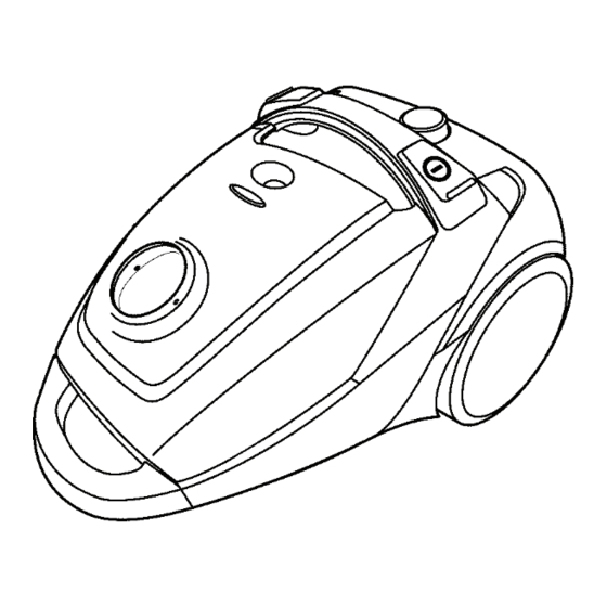
Page 3: Location Of Controls And Components
2 Location of Controls and Components... -
Page 5: Troubleshooting Guide
3 Troubleshooting Guide CONDITION CHECKPOINT METHOD OF INSPECTION CAUSE / REMEDY When dust is vacuumed off, the Air inlet Check whether or not dust or for- Wipe the dust sensor with a dry dust sensor indicator lamp doesn’t eign substances adhere to the dust soft cloth. -
Page 6: Disassembly And Assembly Instructions
4 Disassembly and Assembly Instructions Important notice: Before replacing any components, make sure to turn OFF the vacuum cleaner. Remove the power plug from the outlet. 4.1. Dust box cover assembly 3. Remove the connectors from the lead wire AU and P.C.B. removal 1. -
Page 7: Separate The Upper And Lower Body Units
4.2. Separate the upper and lower 3. Lift the upper body U to separate it from the lower body U. body units 1. Remove the five screws fixing the upper body U and lower body U. 4.3. Printed circuit board assembly (P.C.B Ass’y) removal 1. - Page 8 4. Remove the P.C.B. Ass'y from the P.C.B. holder. 6. Remove the Control and Lead wiire BU. * When removing the P.C.B Ass’y, widen the frame of the P.C.B holder, and then remove the P.C.B from the hook of the P.C.B holder. Note: When removing the P.C.B.
-
Page 9: Motor Removal
4.4. Motor removal * Note: When the thermal protector has been replaced, make sure to paste the tape (gasket V) back 1. Lift the motor section from the lower body U. on the terminals. 4.5. Replacement of the indicator ornamental plate unit 1. -
Page 10: Replacement Of The P.c.b. Du, P.c.b. Ku
3. Turn it over to remove the indicator ornamental plate unit. 3. Remove the P.C.B. KU. 4. Remove the air inlet guide U and then remove the lead 4.6. Replacement of the P.C.B. DU, wire AU from the P.C.B. DU. P.C.B. -
Page 11: Cord Reel Partition Unit Replacement
6. Similarly, remove the LED lamp printed circuit board from * For easy removal, pull out the cord slightly, and then lift the cord reel. the Air inlet guide U. 4.8. Rail base U replacement 4.7. Cord reel partition unit 1. -
Page 12: Spring-Loaded Cord Reel Pre-Winding
4.9. Spring-loaded cord reel 4.10.2. Separation of the floor nozzle upper U from the floor nozzle pre-winding lower U 1. The cord reel partition U has a spring that pre-winds the 1. Remove the four screws fixing the floor nozzle lower U. cord reel. - Page 13 4.10.4. Removal of the floor nozzle brush CU.DU.EU.FU 1. Turn the floor nozzle lower unit over. Insert the tip of a flat-blade screwdriver into the ditch in the brush installa- tion part, then remove the brush.(Fig.32)
-
Page 14: Wiring Connection Diagram
5 Wiring Connection Diagram MODEL MC-CG677 / CG677K... -
Page 15: Exploded View And Replacement Parts List
6 Exploded View and Replacement Parts List 6.1. EXPLODED VIEW (ATTACHMENTS) " & " &... -
Page 16: Parts List (Attachments)
6.2. PARTS LIST (ATTACHMENTS) Safety Ref No. PART NO. PART NAME & DESCRIPTION Q'TY Remarks AMC94P-YD0SE HOSE ASS'Y AMC99P-ZF06E EXTENSION WAND UNIT AMC99R-ZF0VE TURBIN NOZZLE (Floor Nozzle) AMC60R-UA0VE CREVICE TOOL (Crevice Nozzle) AMC88R-UA0VE DUSTING BRUSH AMC98R-ZF00E FLOOR NOZZLE UPPER UNIT AMC18R-ZF02E NOZZLE LEVER AMC78Z-ZF0VE... -
Page 17: Exploded View (Body Unit)
6.3. EXPLODED VIEW (BODY UNIT) & " " & " & !" "! " "" " " "# "% !& "& "$ "' #& #"... -
Page 18: Parts List (Body Unit)
6.4. PARTS LIST (BODY UNIT) Safety Ref No. PART NO. PART NAME & DESCRIPTION Q'TY Remarks AMV93K-4K0KE DUST COVER ASS'Y AMV94M-4K0SE INDICATOR PLATE UNIT Silver AMV66J-4K00E AMV64H-4K00E SUCTION INLET PACKING AMV67V-4K00E LEAD WIRE A UNIT AMV87V-4K00E PRINTED CIRCUIT BOARD AMV80J-4K0KE AIR INLET GUIDE UNIT AMV66H-4K00E SUCTION INLET PACKING... -
Page 19: Packing Instructions
6.5. PACKING INSTRUCTIONS "... -
Page 20: Packing List
6.6. PACKING LIST Safety Ref No. PART NO. PART NAME & DESCRIPTION Q'TY Remarks AMV61Z-4K0SE CARTON BOX AMC49Z-YD00E PARTITION BOARD A AMC69Z-YD00E CUSHION A AMC10Z-YD00E BODY BAG AMV01Z-4K008 OPERATING INSTRUCTIONS MC-CG677K Only UK AMV01Z-4K00E OPERATING INSTRUCTIONS MC-CG677 Europe.Switzerland...