
Related Manuals for Siemens Simatic box pc 627b


Summary of Contents for Siemens Simatic box pc 627b
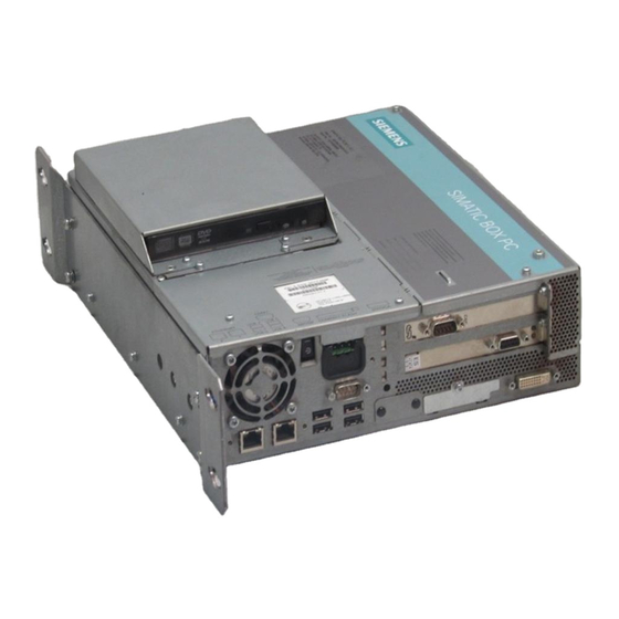
- Page 1 Operating Instructions Edition 05/2006 SIMATIC Industrial PC SIMATIC Box PC 627 Industrial PC Box PC 627 simatic DOCUMENTATION DOCUMENTATION...
- Page 3 Introduction Safety Information Description SIMATIC Application Planning Industrial PC SIMATIC Box PC 627 Installation Connecting Operating Instructions Commissioning Integration Functions Expansions and configuration Maintenance and service Alarm, Error and System Messages Troubleshooting Technical Data Dimensional Drawings Detailed descriptions Appendix ESD Guidelines Release 05/2006 A5E00362052-03 Abbreviations...
-
Page 4: A5E00362052
Trademarks All names identified by ® are registered trademarks of the Siemens AG. The remaining trademarks in this publication may be trademarks whose use by third parties for their own purposes could violate the rights of the owner. -
Page 5: Table Of Contents
Table of contents Introduction............................. 1-1 Preface............................1-1 Guideline to the operating instructions ..................1-2 Safety Information........................... 2-1 General safety instructions ......................2-1 Description.............................. 3-1 Overview ............................ 3-1 Areas of application ........................3-2 Benefits ............................3-2 Function ............................. 3-3 Features ............................. 3-3 Windows XP Embedded ...................... - Page 6 Table of contents Commissioning ............................7-1 Requirements for commissioning....................7-1 Basic commissioning - initial startup ..................7-1 Windows XP Security Center ..................... 7-2 Switching off the device ......................7-2 Notes on operation........................7-3 7.5.1 DVD ROM/CD RW ........................7-3 7.5.2 2HDD/RAID system (optional) ....................
- Page 7 Table of contents 11.2.2 Windows XP Professional / Windows 2000 MUI ..............11-19 11.2.2.1 General installation procedure ....................11-19 11.2.2.2 Restoring the Software to Factory State Using the Restore DVD ......... 11-19 11.2.2.3 Setting up the operating system via the Recovery CD ............11-21 11.3 Partitioning the hard disk .......................
- Page 8 Table of contents 16.2.4 PCI slot pin assignment ......................16-19 16.2.5 Pin assignment 12V power supply connection for WinAC module ........16-20 16.3 System resources ........................16-21 16.3.1 Currently allocated system resources..................16-21 16.3.2 System resources used by the BIOS/DOS ................16-21 16.3.2.1 I/O address allocation ......................
-
Page 9: Introduction
Introduction Preface Purpose of this document These operating instructions contain all the information you need for commissioning and using the SIMATIC Box PC 627. It is intended both for programming and testing personnel who commission the device and connect it with other units (automation systems, additional programming devices), as well as for service and maintenance personnel who install add-ons or carry out fault/error analyses. -
Page 10: Guideline To The Operating Instructions
Introduction 1.2 Guideline to the operating instructions Guideline to the operating instructions Contents format Contents Contents Organization of the documentation, including the index of pages and chapters Introduction Purpose, layout and description of the important topics. Safety information Refers to all the valid safety-related aspects which are derived from statutory regulations and should be adhered to when installing, commissioning and operating the product/system. -
Page 11: Safety Information
Safety Information General safety instructions Caution Please observe the safety instructions on the back of the cover sheet of this documentation. You should not expand your device unless you have read the relevant safety instructions. This device is compliant with the relevant safety measures to IEC, EN, VDE, UL, and CSA. If you have questions about the validity of the installation in the planned environment, please contact your service representative. - Page 12 Safety Information 2.1 General safety instructions Battery This device is equipped with a Lithium battery. Batteries may only be replaced by qualified personnel. Caution There is the risk of an explosion if the battery is not replaced as directed. Replace only with the same type or with an equivalent type recommended by the manufacturer.
-
Page 13: Description
Description Overview The SIMATIC Box PC 627 is especially suited for industrial PC applications and delivers high processor performance in compact space: • Compact design • Expandable (2 PCI slots) • High performance • Rugged SIMATIC Box PC 627 SIMATIC Box PC 627 Operating Instructions, Release 05/2006, A5E00362052-03... -
Page 14: Areas Of Application
Description 3.2 Areas of application Areas of application The SIMATIC Box PC 627 provides engineers building machines, plants and switch cabinets with a high performance, expandable PC platform for industrial application on the plant floor: • Measurement, controlling and regulation of process and machine data, for example, for redundant process control systems and transport systems in production facilities •... -
Page 15: Function
Description 3.4 Function Function • Integrated configurable monitoring functions (program execution (watchdog) for internal housing temperature, processor temperatures, disk drive temperatures and RPM of the two fans) • Enhanced diagnostics / messaging via Ethernet, e-mail, SMS, and for direct input in SIMATIC software applications via OPC (optional via SIMATIC PC DiagMonitor ≥... - Page 16 Description 3.5 Features Basic data Interfaces Ethernet 2x 10/100 Mbps (RJ45) PROFIBUS / MPI 12 Mbps (isolated potential, compatible to CP 5611), optional External: 4x USB 2.0 high current (max. 2 can be simultaneously operated as high current) Internal: 1x USB 2.0 high current, 1x USB 2.0 low current Front panel ports: 1x USB 1.1, 1x USB 2.0, both high current Serial V.24 interface...
-
Page 17: Windows Xp Embedded
Description 3.6 Windows XP Embedded Windows XP Embedded The overview shows the most important device functions under Windows XP Embedded: Function Compact Flash card version Enhanced Write Filter (EWF) In the RAM Safecard on Motherboard (SOM) Available Pagefile Not available System Restore Core Available Not available... -
Page 18: Design
Description 3.7 Design Design 3.7.1 External structure Front view 2 slots for expansion modules Cover for Compact Flash Card slot Front interfaces Power supply fan On / Off switch IEC connector for AC power supply or connection for 24 V DC Rear view Status display: Two part 7 segment display and two LEDs for... - Page 19 Description 3.7 Design Side view (drive side) Mounting for WinAC backup battery (please use the supplied battery mount without cover for WinAC module) Input data of the power supply Drive mount module for hard disks and DVD ROM / CD-RW Bottom Equipotential Bonding SIMATIC Box PC 627...
-
Page 20: Operator Controls
Description 3.7 Design 3.7.2 Operator Controls On / Off switch On / Off switch Description The On / Off switch does not disconnect the device from mains. When the switch is in 0 position (Off), the device is still connected to the auxiliary voltage. Warning The On / Off switch does not disconnect the device from mains. -
Page 21: Connection Elements
Description 3.7 Design 3.7.3 Connection elements Interfaces Arrangement of the ports on the front of the device Description Description DVI/VGA DVI/VGA connection for CRT or LCD monitor with DVI interface, VGA via DVI/VGA adapter Compact Flash Card Slot for Compact Flash Card PROFIBUS/MPI/DP MPI interface (RS485, electrically isolated), 9-pin Cannon socket... - Page 22 Description 3.7 Design Interfaces for connecting operator panels / displays Arrangement of the ports Retaining screw for the steel cover plate that covers the interfaces described below. I/O interface for connecting front panel components USB 2.0 for front LVDS display interface for TFT displays up to 1024 x 768 pixels Access to 2nd LVDS display interface for TFT displays up to 1280 x 1024...
- Page 23 Description 3.7 Design DC power supply Location of the DC power connector Description DC power connector for DC power supply of the device SIMATIC Box PC 627 3-11 Operating Instructions, Release 05/2006, A5E00362052-03...
- Page 24 Description 3.7 Design SIMATIC Box PC 627 3-12 Operating Instructions, Release 05/2006, A5E00362052-03...
-
Page 25: Application Planning
Application Planning Transport Despite the device's rugged design, its internal components are sensitive to severe vibrations or shock. You must therefore protect the PC from severe mechanical stress when transporting it. You should always use the original packaging for shipping and transporting the device. Caution Risk of damage to the device! When transporting the PC in cold weather, it may be submitted to extreme variations in... -
Page 26: Device Identification Data
Application Planning 4.3 Device identification data Device identification data The device can be identified uniquely with the help of these numbers in case of repairs or theft. Enter the following data in the table below: • Serial number: The serial number is found on the rating plate. Rating plate N117 Figure 4-1... -
Page 27: Ambient And Environmental Conditions
Application Planning 4.4 Ambient and environmental conditions Ambient and environmental conditions When you plan your project, you should make allowances for: • The climatic and mechanical environmental conditions specified in the specifications given in your operating manual. • At least 100 mm space should be left free around the ventilation slots, in order that the PC receives sufficient ventilation. -
Page 28: Permitted Mounting Positions
Application Planning 4.5 Permitted mounting positions Permitted mounting positions Fitting positions of the PC according to UL60950-1/UL508/EN60950-1/CSA22.2 No. 60950-1 An inclination of ± 20° is permitted for all approved mounting positions. Position 2 Position 1 (preferred) Position 4 (ceiling) Position 3 (desktop) CD/DVD drive cannot be operated. - Page 29 Application Planning 4.5 Permitted mounting positions Additional permissible PC mounting positions according to UL508/CSA 22.2 No. 142 An inclination of ±15° is allowed in this mounting position. An external fire protection casing is required. Position 5 (ports facing down) Position 6 (ports facing above) CD/DVD drive cannot be operated.
- Page 30 Application Planning 4.5 Permitted mounting positions SIMATIC Box PC 627 Operating Instructions, Release 05/2006, A5E00362052-03...
-
Page 31: Installation
Installation The device is particularly suitable for installation in consoles, switch cabinets and switchboards. Warning Function test while installing the device in machines or execute systems Following the results of a risk analysis, additional protection equipment on the machine or the system is necessary to avoid endangering persons. -
Page 32: Installation Of The Device With The Vertical Mounting Kit
Installation 5.2 Installation of the device with the vertical mounting kit Instructions for ceiling or wall mounting Mounting examples Material Hole diameter Mounting Concrete 8 mm diameter, 60 mm depth Dowel: 8 mm, 50 mm screws 4 mm, 50 mm Plasterboard 14 mm diameter Tilting dowel... - Page 33 Installation 5.2 Installation of the device with the vertical mounting kit Mounting the vertical mounting plate onto the device Remove the equipotential bonding screw (1) from the device and attach it with the vertical mounitng plate (2). Attach the vertical mounting plate with four M4 screws and three M3 screws to the device SIMATIC Box PC 627 Operating Instructions, Release 05/2006, A5E00362052-03...
- Page 34 Installation 5.2 Installation of the device with the vertical mounting kit Note Please note the information on the permissible mounting position in the section "Permissible Mounting Positions" SIMATIC Box PC 627 Operating Instructions, Release 05/2006, A5E00362052-03...
-
Page 35: Connecting
Connecting Connecting peripherals Note before connecting Notice Connect only I/O modules approved for industrial applications to EN 61000-6-2:2001. Note Hot-plug I/O modules (USB) may be connected while the PC is in operation. Caution I/O devices not capable of hot-plugging may only be connected after the device has been disconnected from the power supply. -
Page 36: Connecting The 120 V / 230 V Ac Power Supply
Connecting 6.2 Connecting the 120 V / 230 V Ac power supply Connecting the 120 V / 230 V Ac power supply To be noted before you connect the device Note The varying voltage power supply module is designed for operation on 120/230/240 V AC networks. - Page 37 Connecting 6.2 Connecting the 120 V / 230 V Ac power supply Localized information Outside of the USA and Canada, operation on a 230 V power supply: This device is equipped with a safety-tested power cord which may only be connected to ground contact power outlet.
-
Page 38: Connecting The (24 V) Dc Power Supply
Connecting 6.3 Connecting the (24 V) DC power supply Connecting the (24 V) DC power supply Note before connecting Warning Only connect the device to 24 V DC power supply systems which meet the requirements of a safe extra-low voltage (SELV); in addition, a protective conductor must be connected. The conductors must withstand the short-circuit current of the 24 V DC power source, so that a short-circuit will not damage the cable. -
Page 39: Connecting The Equipotential Bonding Circuit
Connecting 6.4 Connecting the equipotential bonding circuit Connecting the equipotential bonding circuit A low-impedance earth connection ensures that interference signals generated by external power supply cables, signal cables or cables to the I/O modules are safely discharged to earth. Equipotential bonding terminal The equipotential bonding terminal on the device (large surface, large-area contact) must be connected with the... - Page 40 Connecting 6.4 Connecting the equipotential bonding circuit SIMATIC Box PC 627 Operating Instructions, Release 05/2006, A5E00362052-03...
-
Page 41: Commissioning
Commissioning Requirements for commissioning • Connect the peripherals, such as the keyboard, mouse, monitor and the power supply, before putting the device into operation. • The operating system of your device is preinstalled on the hard disk. Caution Risk of damage to the device! Make sufficient allowances for the device to acquire room temperature before you put it into use. -
Page 42: Windows Xp Security Center
Commissioning 7.3 Windows XP Security Center After you have entered all necessary information, and after the operating system setup is completed, the PC is automatically restarted and displays the user interface of the relevant operating system. From now on, after you switch on the PC, the user interface of the operating system is automatically opened when the startup routine is completed. -
Page 43: Notes On Operation
Commissioning 7.5 Notes on operation Notes on operation 7.5.1 DVD ROM/CD RW The DVD-ROM/CD-RW drive is an optional feature. Recording methods supported by the disk drive: Disc at once, Track at once, Session at once, Packet writing, whereby Disc at once und Track at once are recommended due to their compatibility to other optical drives. -
Page 44: Hdd System
Commissioning 7.5 Notes on operation 7.5.2.1 2 HDD system Two 2.5" hard disks are installed in the device depending on the device features. The two hard disks are connected to the SATA ports 0 and 2. The hard disk on SATA port 2 is not configured. - Page 45 Commissioning 7.5 Notes on operation Configuring a RAID1 system Requirements: Two identical SATA hard disks; the primary hard disk contains the operating system and data (boot drive), the second is empty. The default pre-installed operating systems Windows XP or 2000 already include the required drivers and the RAID software (Intel Matrix Storage Manager).
- Page 46 Commissioning 7.5 Notes on operation 7. In the subsequent dialog, select RAID 1 (Mirroring) and enter a name for this configuration. SIMATIC Box PC 627 Operating Instructions, Release 05/2006, A5E00362052-03...
- Page 47 Commissioning 7.5 Notes on operation 8. Now select the hard disk to be used in the RAID 1 system. This is usually the hard disk containing the operating system (default: Port 0). This hard disk is used as the source and its data will later be mirrored to the partner drive.
- Page 48 Commissioning 7.5 Notes on operation The data on the hard disk specified as the source drive will now be copied to the partner drive. The time required to copy the data (migration) depends on the capacity of the hard disk and may take approximately 45-90 minutes. The device can continue to operate during the copy process although at a reduced speed.
- Page 49 Commissioning 7.5 Notes on operation Comments about faults Should a drive fail, the "Intel Matrix Storage Console" application will output a message. This message is recorded in the log file of this program and in the event display of the Windows operating system.
- Page 50 Commissioning 7.5 Notes on operation Solution: Before performing a RAID commissioning, the SIMATIC PC DiagMonitor should be deactivated. Subsequently, it can be reactivated. Measures: If the DiagMonitor Management Station is in operation on your device: • Close all applications, also the Management Station. •...
-
Page 51: Integration
To couple the device to an S7 PLC, you need the software package “SOFTNET for PROFIBUS”. Further information For further information, refer to the catalog and to the online ordering system of Siemens A&D. Internet address: http://www.mall.automation.siemens.com SIMATIC Box PC 627... - Page 52 Integration SIMATIC Box PC 627 Operating Instructions, Release 05/2006, A5E00362052-03...
-
Page 53: Functions
Functions Overview The following individual functions are implemented: • Temperature monitoring and over/under temperature indication • Watchdog • Fan monitoring Messages can be output from the monitoring modules to the applications. The SOM software (Safecard On Motherboard) and DiagMonitor software on CD (optional) are available for this. -
Page 54: Watchdog (Wd)
Functions 9.3 Watchdog (WD) Watchdog (WD) Function The watchdog monitors the program execution and reports a program crash to the user by means of various reactions. The watchdog is idle when the PC is switched on or after a HW-RESET(cold restart), i.e., no reaction of the WD is triggered. -
Page 55: Safecard On Motherboard (Som)
Functions 9.5 Safecard on Motherboard (SOM) Safecard on Motherboard (SOM) This application is used to monitor PC hardware (temperature, watchdog and fans) and to display the current measured values. A GUI is used to configure the application and also to activate the temperature monitoring watchdog function and fan monitoring function. -
Page 56: Status Display
Functions 9.6 Status display Status display The status display consists of two 7-segment displays with two dual-color LEDs. LED H2 LED H1 2 x 7-segment display Function of the 7-segment displays The POST codes of the respective test step are displayed during the startup of the BIOS. The POST code of the most recently started test step is displayed should an error occur. -
Page 57: Expansions And Configuration
Expansions and configuration 10.1 Opening the Device 10.1 Caution Work on the open device may only be carried out by authorized and qualified personnel. Within the warranty time, you are only allowed to install expansions for memory and expansion card modules. Caution The device contains electronic components which may be destroyed by electrostatic charge. - Page 58 Expansions and configuration 10.1 Opening the Device Open the device up Steps for opening the device Unscrew 2 screws (1). Swing the cover up and remove SIMATIC Box PC 627 10-2 Operating Instructions, Release 05/2006, A5E00362052-03...
-
Page 59: Memory Expansion
Expansions and configuration 10.2 Memory expansion 10.2 Memory expansion 10.2 10.2.1 Removing/Installing Memory Module Memory expansion options The motherboard is equipped with 2 slots for memory modules. For 184-pin DDR2 RAM chips, unbuffered, no ECC. This allows you to expand the memory capacity of your PC to a maximum of 2 GB. - Page 60 Expansions and configuration 10.2 Memory expansion Installing a memory module How to install a memory module Open the device Note where the (polarized) cutout is on the pin side of the RAM chip before inserting it Push the module carefully into the slot until the interlocks engage Close the device.
- Page 61 Expansions and configuration 10.2 Memory expansion Removing a memory module How to remove a memory module Open the device Open the left and right interlocks Pull the memory module out of the slot Close the device. Display of the current memory configuration A new memory module is automatically detected.
-
Page 62: Installing Pci Expansion Cards
Expansions and configuration 10.3 Installing PCI expansion cards 10.3 Installing PCI expansion cards 10.3 10.3.1 Notes on the modules The device is designed for use with modules conforming to PCI specifications V 2.2. PCI modules with 5 V and 3.3 V supply voltage can be operated. The permitted dimensions of the modules are found in the dimensional drawings section. - Page 63 Expansions and configuration 10.3 Installing PCI expansion cards Inserting the slider To insert the slider: How to install a slider Push the slider through the guide slot until it is seated firmly on the module. Insert the module into the slot.
-
Page 64: Installing Disk Drives
Expansions and configuration 10.4 Installing disk drives 10.4 Installing disk drives 10.4 10.4.1 Options of installing disk drives Drive bay module for hard disks and DVD-ROM/CD-RW drives DVD-ROM/CD-RW drive bay Pos Description DVD-ROM/CD-RW drive bay Mounting slot for DVD-ROM or DVD-ROM/CD-RW drive One 3.5"... - Page 65 Expansions and configuration 10.4 Installing disk drives Two 2.5" hard disks Pos Description Hard disk drive bay for two 2.5" hard disks Two mounting slots for 2.5" hard disks SIMATIC Box PC 627 10-9 Operating Instructions, Release 05/2006, A5E00362052-03...
-
Page 66: Installing/Removing A Drive Bay Module
Expansions and configuration 10.4 Installing disk drives 10.4.2 Installing/removing a drive bay module Preparations Disconnect the device from mains and unplug all cables. Removing a drive bay for hard disks / DVD/CD-RW Steps for removing the drive bay Unscrew 4 screws (1). Lift out the drive bay module for hard disks and DVD / CD-RW drives and set it down on the... -
Page 67: Installing And Removing Dvd-Rom/Cd-Rw Drives
Expansions and configuration 10.4 Installing disk drives 10.4.3 Installing and removing DVD-ROM/CD-RW drives Removing a DVD-ROM/CD-RW How to remove the DVD-ROM/CD-RW drive Remove the drive bay module. Remove the 2 screws (1) on the DVD-ROM/CD-RW drive bay Remove the 3 fastening screws (2) of the drive Remove the 2 screws (3) of the adapter board... -
Page 68: Installing / Removing Hard Disks
Expansions and configuration 10.4 Installing disk drives 10.4.4 Installing / removing hard disks Removing 2.5" drives How to remove 2.5" drives Remove the drive bay module. Unscrew the four screws of the drive (1) Remove the drive and the steel mounting bracket from the bay Disconnect the cable and the power supply adapter from the drive SIMATIC Box PC 627 10-12... - Page 69 Expansions and configuration 10.4 Installing disk drives Removing 3.5" drives How to remove 3.5" drives Remove the drive bay module. Disconnect the power supply and the data cable from the drive Remove the 4 screws (1) of the drive Take the drive out of the bay Note Note that special screws with inch threads (6-32 x 3/16'' St G3E) are used! SIMATIC Box PC 627...
-
Page 70: Installing/Removing A Compact Flash Card
Expansions and configuration 10.5 Installing/removing a Compact Flash card 10.5 Installing/removing a Compact Flash card 10.5 Memory expansion options The device features a card reader slot for Compact Flash cards (types I / II). We recommend Compact Flash cards for industrial application (industrial grade cards from the company SANDISK, for example). - Page 71 Expansions and configuration 10.5 Installing/removing a Compact Flash card Steps for opening the board slot Slide the cover of the board slot in the direction of the DVI connector and lift it up Installing a Compact Flash card Steps for installing a Compact Flash card Open the board slot.
- Page 72 Expansions and configuration 10.5 Installing/removing a Compact Flash card Note The Compact Flash slot is coded against reversed insertion. Insert the Compact Flash card so that its label side is facing the front panel of the PC. Caution If the Compact Flash card meets resistance, flip it over. Never insert the Compact Flash card with force.
-
Page 73: Maintenance And Service
Notice Note the ESD instructions. Limitation of Liability All technical specifications and licenses apply only to expansions approved by SIEMENS. No liability can be accepted for impairment of functions caused by the use of devices and components of other manufacturers. -
Page 74: Replacing The Backup Battery
Maintenance and service 11.1 Removing and installing hardware components Tools You can perform all installation tasks on the device using Torx T6, Torx T10 and Torx T20 screwdrivers and a Philips screwdriver. 11.1.2 Replacing the Backup Battery Note Batteries are wearing parts and should be replaced every five years in order to ensure proper functioning of the PC. - Page 75 Maintenance and service 11.1 Removing and installing hardware components Preparation Note For the BIOS setting "Profile: Standard" the configuration data of the device is deleted when the battery is replaced. For the BIOS setting "Profile: User" the configuration data of the device is retained; only the date and time has to be reconfigured.
- Page 76 Maintenance and service 11.1 Removing and installing hardware components Steps for replacing the battery Remove the battery holder. Unplug the cable. Remove the old battery from the holder. Place a new battery in the holder and reconnect the battery plug. Close the battery compartment.
-
Page 77: Removing/Installing The Power Supply
Maintenance and service 11.1 Removing and installing hardware components 11.1.3 Removing/Installing the Power Supply Warning Only qualified personnel is authorized to exchange the power supply module. Preparations 1. Disconnect the device from mains and unplug all cables. 2. Open the device. Removing the power supply module How to remove the power supply module Remove the hard disk,... - Page 78 Maintenance and service 11.1 Removing and installing hardware components How to remove the power supply module Remove the 2 fastening screws (1) (Torx T10). Pull out the plug (1) from the power supply module. Lift out the power supply module. SIMATIC Box PC 627 11-6 Operating Instructions, Release 05/2006, A5E00362052-03...
-
Page 79: Installing / Removing The Bus Board
Maintenance and service 11.1 Removing and installing hardware components 11.1.4 Installing / removing the bus board Preparation 1. Disconnect the device from mains and unplug all cables. 2. Open the device. Removing the bus board How to remove the bus board Remove all modules from their slots. -
Page 80: Installing / Removing The Motherboard
Maintenance and service 11.1 Removing and installing hardware components How to remove the bus board Remove the 2 screws on the housing. Remove the bus board from the motherboard. 11.1.5 Installing / removing the motherboard Preparation 1. Disconnect the device from mains and unplug all cables. 2. - Page 81 Maintenance and service 11.1 Removing and installing hardware components How to remove the motherboard Remove the 6 screws (1) and the processor fan: Unscrew 4 screws (2). Remove the 4 hexagonal bolts on the interfaces. Lift out the motherboard. SIMATIC Box PC 627 11-9 Operating Instructions, Release 05/2006, A5E00362052-03...
-
Page 82: Installing / Removing The Equipment Fan
Maintenance and service 11.1 Removing and installing hardware components 11.1.6 Installing / removing the equipment fan Preparations 1. Disconnect the device from mains. 2. Open the device Removing the fan How to remove the fan Unplug the fan connector from the motherboard Remove the 4 plastic rivets on the housing... - Page 83 Maintenance and service 11.1 Removing and installing hardware components Installing the fan Notice Always install a fan of the same type! Fan mounting position The figure shows the correct fan mounting position. Pay attention to the direction of the arrow on the fan enclosure! SIMATIC Box PC 627 11-11 Operating Instructions, Release 05/2006, A5E00362052-03...
-
Page 84: Installing / Removing The Power Supply Fan
Maintenance and service 11.1 Removing and installing hardware components 11.1.7 Installing / removing the power supply fan Preparations 1. Disconnect the device from mains. 2. Open the device 3. Removing the power supply module Removing the fan How to remove the fan Unplug the power supply connector. - Page 85 Maintenance and service 11.1 Removing and installing hardware components Installing the fan Notice Always install a fan of the same type! Fan mounting position The diagram shows the correct mounting position of the fan (1). Pay attention to the direction of the arrow on the fan enclosure! SIMATIC Box PC 627 11-13...
-
Page 86: Installing / Removing The Processor
Maintenance and service 11.1 Removing and installing hardware components 11.1.8 Installing / removing the processor Caution The processor replacement may only be carried out by authorized qualified personnel. Preparation 1. Unplug the device from mains. 2. Open the device. Removing the processor How to remove the processor Remove the 4 screws holding the processor heat sink and remove... - Page 87 Maintenance and service 11.1 Removing and installing hardware components How to remove the processor Opening the processor latch Removing the processor SIMATIC Box PC 627 11-15 Operating Instructions, Release 05/2006, A5E00362052-03...
- Page 88 Maintenance and service 11.1 Removing and installing hardware components Installing the processor How to install the processor Inserting the processor Notice When you insert the processor, make sure the notches of the processor and of the socket match up. Close the processor latch Apply some heat-conductive paste to the processor Caution The processor may overheat when the system is in operation!
-
Page 89: Reinstalling The Operating System
Maintenance and service 11.2 Reinstalling the Operating System 11.2 Reinstalling the Operating System 11.2 11.2.1 Windows XP Embedded 11.2.1.1 General installation procedure If your software becomes corrupt for any reason, you can reinstall it from the Restore CD. The Restore CD contains a image file for the hard disk or CF card with the original software (operating system with installed hardware drivers) and forms part of the scope of delivery of the device. - Page 90 Maintenance and service 11.2 Reinstalling the Operating System 3. Select the Boot menu and move the entry "CD-ROM Drive" to the first position. 4. End the BIOS setup with the "Exit Saving Changes" entry. 5. Now follow the instructions on the screen. Caution All existing data, programs, user settings and authorizations or license keys will be deleted from the hard disk and therefore lost.
-
Page 91: Windows Xp Professional / Windows 2000 Mui
Maintenance and service 11.2 Reinstalling the Operating System 11.2.2 Windows XP Professional / Windows 2000 MUI 11.2.2.1 General installation procedure If your software becomes corrupt for any reason, you have two possibilities: • Restoring the factory state of the software by means of the Restore DVD The Restore DVD contains an image of the original supplied software (operating system with installed drivers) and is included in the Windows XP Professional variant. - Page 92 Maintenance and service 11.2 Reinstalling the Operating System Restoring the factory state To restore the factory state, proceed as follows: 1. If the device does not have an optical drive, connect a USB DVD-ROM drive to the device. 2. Insert the Restore DVD in the drive and reboot the device. When the BIOS message appears, press <F2>...
-
Page 93: Setting Up The Operating System Via The Recovery Cd
1. Insert the Recovery CD in your drive and reboot the device. When the BIOS message ”Press <F2> to enter Setup or <ESC> to show Boot Menu" appears, press the ESC key. After initialization, a "Boot Menu" is displayed. 2. Follow the on-screen instructions until the "Siemens SIMATIC Recovery" window appears. Partition setup... - Page 94 1. Boot from the Recovery CD and then follow the screen instructions until the Recovery functions window is displayed. 2. Start the DiskPart program in the "Siemens SIMATIC Recovery“ window and enter the following commands in the displayed command interface: list disk Displays all available hard disks.
- Page 95 The recovery CD contains encrypted data that can only be transferred to this system. 1. Boot from the Recovery CD and then follow the screen instructions until the Recovery functions window is displayed. 2. Select "Recovery Windows ..." in the "Siemens SIMATIC Recovery" window. 3. Follow the instructions on the screen. Note...
- Page 96 Maintenance and service 11.2 Reinstalling the Operating System Setting up the language selection for Windows XP Professional The Multilanguage User Interface (MUI) allows you to set up the Windows XP Professional menus and dialogs for additional languages. To install the MUI, start "MUI-german"...
-
Page 97: Partitioning The Hard Disk
Maintenance and service 11.3 Partitioning the hard disk 11.3 Partitioning the hard disk 11.3 11.3.1 Setting up the partitions under Windows XP Embedded After you have installed a new hard disk, or if partitions are faulty, or when you wish to change the partitioning on your hard disk, you need to create or reconfigure partitions on the hard disk Partitioning the Compact Flash card... -
Page 98: Install Drivers And Software
Maintenance and service 11.4 Install drivers and software 11.4 Install drivers and software 11.4 Notice Before you install new drivers or updates for multilingual operating systems, (MUI versions),the regional settings for menus and dialogs and the default language must be reset to US English. -
Page 99: Install Raid Controller Software
Maintenance and service 11.5 Install RAID Controller Software 11.5 Install RAID Controller Software 11.5 The procedure for installing the software can be found in the RAID user manual on the supplied "Documentation and Drivers" CD. Note concerning Windows 2000 Professional / XP Professional You need to select the Intel 82801FR SATA RAID Controller from the provided list when installing Windows 2000 Professional /XP Professional for the first time. -
Page 100: Installing Or Updating Application Programs And Drivers
Compact Flash cards or hard disks as well as individual partitions (images). The software can be ordered from the Siemens A&D online ordering system. For detailed information about SIMATIC PC/PG Image Creator, please refer to the corresponding product documentation. -
Page 101: Alarm, Error And System Messages
Alarm, Error and System Messages 12.1 Boot error messages 12.1 During startup (the boot process), the BIOS first performs a Power On Self Test (POST) and checks whether certain functional units of the PC are operating error-free. When an error occurs within this phase, the BIOS outputs a tone sequence (beep code) based on the current test result. - Page 102 Alarm, Error and System Messages 12.1 Boot error messages On-screen error message Meaning / suggestions System RAM Failed at offset: Memory error. Contact your technical support team. Shadow RAM Failed at offset: Memory error. Contact your technical support team. Extended RAM Failed at offset: Memory error.
-
Page 103: Bios Post Codes
Alarm, Error and System Messages 12.2 BIOS POST codes 12.2 BIOS POST codes 12.2 The following section lists the POST codes relevant to users in the sequence in which they occur: Contact Customer Support for all other POST codes. Display Meaning Description Remedy... - Page 104 Alarm, Error and System Messages 12.2 BIOS POST codes Special codes The following Beep codes are available in addition to the listed POST codes: • 3 x short INSERT key is pressed on system start: If an external graphics card on the bus board is not detected, you can try to activate it by pressing the INSERT key.
-
Page 105: Troubleshooting
Troubleshooting 13.1 General problems 13.1 This chapter provides you with tips on how to localize and troubleshoot frequently occurring problems. Problem Possible causes To correct or avoid error Check the power supply, the network cable and the power plug. The device is not There is no power supply •... -
Page 106: Problems When Using Modules Of Third-Party Manufacturers
PC. If the error no longer occurs, the third- party module was the cause of the fault. Replace this Connector assignments deviate. • module with a Siemens module or contact the module “Reset Configuration” in BIOS • supplier. -
Page 107: Display A Temperature Fault By Means Of The Som Application
Troubleshooting 13.3 Display a temperature fault by means of the SOM application 13.3 Display a temperature fault by means of the SOM application 13.3 Cause Temperature errors do not occur during the normal approved use of the device. Should the "TEMP"... - Page 108 Troubleshooting 13.3 Display a temperature fault by means of the SOM application SIMATIC Box PC 627 13-4 Operating Instructions, Release 05/2006, A5E00362052-03...
-
Page 109: Technical Data
Technical Data 14.1 General Specifications 14.1 General technical data Order numbers 6ES7647-6Axxx-xxxx Dimensions Without DVD/CD-RW: 297x267x80 (WxHxD in mm) With DVD/CD-RW: 297x267x100 Weight approx. 7 kg Supply voltage (AC) Nominal 100 - 240 V AC (-15% / +10%) (autorange) Supply voltage (DC) Nominal 24 V DC (-15% / + 20%), SELV Input current AC Steady-state current up to 2.3 A (on start-up, up to 50A for... -
Page 110: 14.1 General Specifications
Technical Data 14.1 General Specifications General technical data Immunity to discharges of static ± 6 kV contact discharge (according to IEC 61000-4–2) electricity ± 8 kV air discharge (according to IEC 61000-4-2) Immunity to RF interference 10 V/m 80–1000 MHz, 80% AM (according to IEC 61000-4-3) 10 V/m 900 MHz u. - Page 111 Technical Data 14.1 General Specifications General technical data Disk drives Hard disk 3.5" / 2.5" Serial ATA, See order documentation for hard disk capacity - 1.5 Gbit/s data transmission rate - supports NCQ (Native Command Queuing; SATA II property) CD-ROM, DVD-ROM/CD-RW ATA 33, See order documentation for features ∗2 Graphic...
-
Page 112: Power Requirements Of The Components
Technical Data 14.2 Power requirements of the components restriction for installation with leaf mounting kit Vibration: 10-58 Hz: 0.0375 mm / 58-500 Hz: 4.9 m/s shock resistance: 25 m/s , 30 ms Optional product feature Electrically isolated within the safety extra-low voltage circuit (SELV) 14.2 Power requirements of the components 14.2... -
Page 113: Ac Voltage Supply
Technical Data 14.3 AC voltage supply 14.3 AC voltage supply 14.3 Technical data Degree of protection IP20 (in installed state) Protection class VDE 0106 Note The power supply contains an active PFC (Power Factor Correction) circuit to conform to the EMC guidelines. -
Page 114: Dc Power Supply
Technical Data 14.4 DC power supply 14.4 DC power supply 14.4 Technical data Degree of protection IP20 (in installed state) Protection class VDE 0106 Output voltages Voltage Max. current + 12 V 6,5 A peak 8 A - 12 V 0,3 A + 5 V 16.5 A... -
Page 115: Dimensional Drawings
Dimensional Drawings 15.1 Dimensional Drawing of the Device 15.1 Figure 15-1 Dimensional drawing for mounting with angle bracket SIMATIC Box PC 627 15-1 Operating Instructions, Release 05/2006, A5E00362052-03... - Page 116 Dimensional Drawings 15.1 Dimensional Drawing of the Device Figure 15-2 Dimensional drawing for mounting without angle bracket Notice When mounting devices with optical drives or WinAC backup batteries change the fitting depth. SIMATIC Box PC 627 15-2 Operating Instructions, Release 05/2006, A5E00362052-03...
- Page 117 Dimensional Drawings 15.1 Dimensional Drawing of the Device Figure 15-3 Dimensional drawing for mounting with the vertical mounting kit SIMATIC Box PC 627 15-3 Operating Instructions, Release 05/2006, A5E00362052-03...
-
Page 118: Dimensional Drawings For The Installation Of Expansion Modules
Dimensional Drawings 15.2 Dimensional drawings for the installation of expansion modules 15.2 Dimensional drawings for the installation of expansion modules 15.2 Figure 15-4 Short PCI modules (5V) Figure 15-5 Maximum size of PCI module SIMATIC Box PC 627 15-4 Operating Instructions, Release 05/2006, A5E00362052-03... -
Page 119: Detailed Descriptions
Detailed descriptions 16.1 Motherboard 16.1 16.1.1 Structure and functions of the motherboard The essential components of the motherboard are the processor and the chip set, two slots for memory modules, internal and external interfaces and the Flash BIOS. Processor heat sink Two memory module slots Slot for the bus board SIMATIC Box PC 627... -
Page 120: Technical Features Of The Motherboard
Detailed descriptions 16.1 Motherboard 16.1.2 Technical features of the motherboard Component / Description Characteristics interface Chip set Single chip set Mobile Intel 915 GM BIOS Update by means of software Phoenix BIOS V05.01.xx (with Profibus) • Intel ® Pentium M / Upgradable Intel ®... -
Page 121: Position Of The Ports On The Motherboard
Detailed descriptions 16.1 Motherboard 16.1.3 Position of the ports on the motherboard Interfaces The motherboard of the device features the following interfaces: • Interfaces for the connection of external devices • Interfaces for internal connections (drives, bus boards etc.) The figure below shows the location of the internal and external interfaces on the motherboard. -
Page 122: External Ports
Detailed descriptions 16.1 Motherboard 16.1.4 External ports Interface Position Connector Description USB 2.0 external X40 lower USB channel 0, X40 upper USB channel 2 X41 lower USB channel 4, X41 upper USB channel 5 PROFIBUS / MPI external X600 9-pin, standard socket, potentially isolated port Ethernet external X500 X501... - Page 123 Detailed descriptions 16.1 Motherboard PROFIBUS / MPI interface, X600 PROFIBUS/MPI interface PinNo. Abbreviation Meaning Input /Output – Not assigned – – Unassigned – LTG_B Signal line B of MPI module Input/output RTS_AS RTSAS, control signal for received data Input stream. The signal is "1" active when the directly connected PLC is sending.
- Page 124 Detailed descriptions 16.1 Motherboard Ethernet RJ45 connection, X500, X501 Ethernet RJ45 connection PinNo. Abbreviation Meaning Input /Output Transmitted data Output Transmitted data Output Received data Input 4, 5 SYMR Internal 75-Ohm terminating resistor – Received data Input 7, 8 SYMT Internal 75-Ohm terminating resistor –...
- Page 125 Detailed descriptions 16.1 Motherboard DVI-I port, X302 DVI-I port PinNo. Abbreviation Meaning Input /Output Ground – Ground – Output Green Output Blue Output HSYNC Horizontal synchronizing pulse Output Ground – Ground – TX2N TDMS data 2- Output TX2P TDMS data 2+ Output Ground –...
- Page 126 Detailed descriptions 16.1 Motherboard Compact Flash Card, X4 Compact Flash card port Pin No. Abbreviation Meaning RESET# Reset (output) CS0# Chip select 0(output) CS1# Chip select 1(output) IORD# I/O read (output) IOWR# I/O write (output) 20, 19, 18, A0-A2 Address bit 0-2 (output) 17, 16, 15, 14, 12, 11, 10, 8 A3-A10 Address bit 3-10 (output) to ground...
- Page 127 Detailed descriptions 16.1 Motherboard Serial port COM1, X135 The COM1 serial port has the following pin assignment: Serial interface COM1 PinNo. Abbreviation Meaning Input /Output DCD (M5) Receiving signal level carrier Input RxD (D2) Received data Input TxD (D1) Transmitted data Output DTR (S1) Data terminal ready...
-
Page 128: Front Ports
Detailed descriptions 16.1 Motherboard 16.1.5 Front ports Overview Ports Position Connector Description Display (LVDS) Internal X400 Connection of LCD displays with LVDS interface (channel 1) Display (LVDS) Internal X401 Connection of LCD displays with LVDS interface (channel 2) I/O front Internal Ports for front I/O front, including USB channel 1... - Page 129 Detailed descriptions 16.1 Motherboard Pin–No. Short description Meaning Input/Output RXCLKIN+ LVDS clock signal (+) Output Ground Ground Not assigned Not assigned Display interface (2nd LVDS channel), X401 Pin–No. Short description Meaning Input/Output Ground Ground RXIN10- LVDS input signal bit 0 (-) Output RXIN10+ LVDS input signal bit 0 (+)
- Page 130 Detailed descriptions 16.1 Motherboard Assignment of the display to the display select pins One of the 15 available displays is configured automatically via the display select inputs. The display select inputs are connected to pull–up resistors, i.e. if these inputs are not interconnected, they are high level.
- Page 131 Detailed descriptions 16.1 Motherboard I/O Front Interface for Operator Panels, X44 This interface carries all signals required for connecting operator panels in addition to the display interface. The maximum cable length is 50 cm at a USB data rate of 12 Mbit/s. Pin–No.
-
Page 132: Internal Interfaces
Detailed descriptions 16.1 Motherboard Pin Assignment of the USB 2.0 interface, X42 Pin–No. Short description Meaning Input/Output + 5 V, fused Output USB5 USB5_M Input/Output USB5 USB5_P Input/Output Ground Shield Shield Note For detailed information on the pin assignments of the interfaces, please contact Customer Support or the Repair Center. - Page 133 Detailed descriptions 16.1 Motherboard Connection for optical drive, X3 Pin No. Abbreviation Meaning Input /Output Reserved Reserved Reserved Reserved Reserved Reserved Ground Reset Reset signal Input /Output Data signal D8 Input /Output Data signal D7 Input /Output Data signal D9 Input /Output Data signal D6 Input /Output...
- Page 134 Detailed descriptions 16.1 Motherboard Pin assignment of the equipment fan, X128 Pin No. Abbreviation Meaning Input /Output Ground +12 V Switched power supply Output CPU FAN_CLK Clock signal Input Pin assignment of the supply for the power supply fan, X129 Pin No.
-
Page 135: Bus Board
Detailed descriptions 16.2 Bus board Pin assignment of the internal USB interface connector, X43 Pin No. Abbreviation Meaning Input /Output VCC 3.3V +3.3V, fused Output VCC 5V + 5 V, fused Output USB3 USB3_M Input /Output USB5 USB5_M Input /Output USB3 USB3_P Input /Output... -
Page 136: Interrupt Assignment (Pci-Irq)
Detailed descriptions 16.2 Bus board 16.2.2 Interrupt assignment (PCI-IRQ) Box PC 627 PCI devices interrupt assignment (PCI-IRQ) INT – A Graphics, USB A (channel 0+1), USB B (channel 2+ 3) INT – B Slot 1 INT – C Slot 2 INT –... -
Page 137: Pci Slot Pin Assignment
Detailed descriptions 16.2 Bus board 16.2.4 PCI slot pin assignment 5V System Environment Side B Side A -12V TRST# +12V Ground INTA# INTB# INTC# INTD# PRSNT1# Reserved Reserved +5V (I/O) PRSNT2# Reserved Ground Ground Ground Ground Reserved Reserved Ground RST# +5V (I/O) Ground GNT#... -
Page 138: Pin Assignment 12V Power Supply Connection For Winac Module
Detailed descriptions 16.2 Bus board 5V System Environment Side B Side A LOCK# +3.3V PERR# SDONE +3.3V SBO# SERR# Ground +3.3V C/BE[1]# AD[15] AD[14] +3.3V Ground AD[13] AD[12] AD[11] AD[10] Ground Ground AD[09] CONNECTOR KEY CONNECTOR KEY AD[08] C/BE[0]# AD[07] +3.3V +3.3V AD[06]... -
Page 139: System Resources
Detailed descriptions 16.3 System resources 16.3 System resources 16.3 16.3.1 Currently allocated system resources All system resources (hardware address, memory configuration, IRQ, DMA channel) are assigned dynamically by the Windows OS, depending on the hardware configuration, drivers and connected peripheral devices. You can view the current configuration of system resources or possible conflicts with the following operating systems: msinfo32 Windows 2000/XP... - Page 140 Detailed descriptions 16.3 System resources I/O address Description of the basic function Possible alternative (hex) function 0092 0092 Basic unit resources 0093 009F DMA controller 00A0 00A1 Programmable interrupt controller 00A4 00A5 Programmable interrupt controller 00A8 00A9 Programmable interrupt controller 00AC 00AD Programmable interrupt controller...
-
Page 141: Interrupt Assignments
Detailed descriptions 16.3 System resources 16.3.2.2 Interrupt Assignments Interrupt Description Comment IRQ0 System timer fixed IRQ1 Keyboard fixed IRQ4 Serial port COM1 IRQ8 Real-time clock (RTC) fixed IRQ9 Microsoft ACPI-Compliant System IRQ13 Numeric processor fixed IRQ14 1. IDE channel (primary) IRQ16 Mobile Intel 915GM/GMS, 910GML Express Chipset Family... -
Page 142: Memory Address Assignments
Detailed descriptions 16.3 System resources 16.3.2.3 Memory address assignments PCI VGA modules can be operated with an expansion ROM of a size up to 48 K. Address Description of the basic function Possible alternative function from 000A 0000 000B FFFF PCI bus 000A 0000 000B FFFF... -
Page 143: Bios Setup
Box PC, for example, the following screen appears after booting: Phoenix BIOS 4.0 Release 6.0 A5E000xxxxx-ES0x Copyright 1985–2002 Phoenix Technologies Ltd.All Rights Reserved. Siemens SIMATIC Box PC 627 Vxx.xx.xx CPU = Intel® Pentium®M CPU X.XX GHz (X.XX depending on the processor) 640K System RAM Passed 127MB Extended RAM Passed Press <F2>... -
Page 144: Bios Setup Menus
Detailed descriptions 16.4 BIOS Setup 16.4.3 BIOS Setup menus The various menus and submenus are listed on the next pages. You can obtain information on the selected SETUP item from the "item-specific help" part of the respective menu. Figure 16-1 SETUP main menu (example) (1) Header (4) Help view... -
Page 145: Main Menu
Detailed descriptions 16.4 BIOS Setup Menu Meaning Main System functions are set here Advanced An extended system configuration can be set here Security Security functions are set here, for example, a password. Boot This is where the boot priority is specified. Version Information about the programming device (for example, release status) can be found here. - Page 146 Detailed descriptions 16.4 BIOS Setup Settings in the main menu In the main menu, you can move up and down to select the following system configuration boxes by means of the [↑] up and [↓] down cursor keys: Field Meaning System Time For viewing and setting the current time System Date...
- Page 147 Detailed descriptions 16.4 BIOS Setup IDE Channel 0 Master, IDE Channel 0 Slave The system jumps to the following submenu when you select this type of menu field: Figure 16-3 IDE Channel 0 Master (example) Type [User] Select “User” if you want to define the hard disk drive. You also need to configure the other options, for example, Cylinder, Heads, Sectors/Track, or other properties of the hard disk drive.
- Page 148 Detailed descriptions 16.4 BIOS Setup LBA Mode “Enabled” in the option “LBA Mode Control” (enabled, disabled) means that hard disk Control capacities greater than 528 MB are supported. The value depends on the drive and should be set only to "Auto" in the "Type" field. Transfer The settings in these fields define the interface data transfer rate.
- Page 149 Detailed descriptions 16.4 BIOS Setup Type [User] Select “User” if you want to define the hard disk drive. You also need to configure the other options, for example, Cylinder, Heads, Sectors/Track, or other properties of the hard disk drive. [Auto] The parameters that you can select here are usually stored on the respective IDE drive.
- Page 150 Detailed descriptions 16.4 BIOS Setup The "Memory Cache" field The following context menu appears when you select the option “Memory cache” in the main menu: Figure 16-5 "Memory Cache" field The cache is a high-speed memory buffer between the CPU and memory (DRAM). Repeated memory access operations are executed in the faster cache, and not in the main memory, provided the feature is enabled.
- Page 151 Detailed descriptions 16.4 BIOS Setup "Boot Options" field The following context menu appears when you select “Boot Options” in the main menu: Figure 16-6 "Boot Options" field Quick Boot Mode Some hardware tests are skipped to speed up the boot sequence. SETUP prompt During the system load phase, the message "Press <F2>...
- Page 152 Detailed descriptions 16.4 BIOS Setup Example of a summary screen: Figure 16-7 Summary screen (example) The Summary screen appears when the system run-up phase completes. SIMATIC Box PC 627 16-34 Operating Instructions, Release 05/2006, A5E00362052-03...
- Page 153 Detailed descriptions 16.4 BIOS Setup "Keyboard Features" field The following submenu appears when you select the option “Keyboard Features” in the main menu: Figure 16-8 "Keyboard Features" submenu (example) Numlock Switches Numlock on or off following power on. If "Auto" is set, this will be remembered the next time the device is switched on.
- Page 154 Detailed descriptions 16.4 BIOS Setup "Hardware Options" field The following submenu, for example, appears when you select “Hardware Options” in the main menu: Figure 16-9 "Hardware Options" submenu (example) The parameters of the interfaces present on the motherboard are set here. Entry Meaning PCI-MPI/DP...
- Page 155 Detailed descriptions 16.4 BIOS Setup Entry Meaning Fan Control [Enabled] The fan speed is controlled based on the temperature. [Disabled] The fan always runs at full speed. CRT / LCD selection [CRT only] A CRT monitor is addressed, or a DVI LCD monitor, if it is connected to the DVI ports when the system boots up.
-
Page 156: Advanced Menu
Detailed descriptions 16.4 BIOS Setup 16.4.5 Advanced Menu Menu layout Figure 16-10 Advanced menu Settings in the Advanced Menu Installed O/S Plug&Play means that all modules are automatically detected and installed, providing they support the Plug&Play functionality. [Other] BIOS handles the entire Plug&Play capability, default setting. [WinXP/2000] The operating system handles the Plug&Play functions. - Page 157 Detailed descriptions 16.4 BIOS Setup “I/0 Device Configuration” submenu Figure 16-11 COM/LPT configuration submenu The resources used by an interface are released when you disable the interface in question. The I/O addresses and interrupts are pre-assigned; it is advisable not to change these default assignments.
- Page 158 Detailed descriptions 16.4 BIOS Setup "PCI Configuration" submenu Figure 16-12 PCI Configuration submenu (example) SIMATIC Box PC 627 16-40 Operating Instructions, Release 05/2006, A5E00362052-03...
- Page 159 Detailed descriptions 16.4 BIOS Setup "PCI Devices" field If the PCI devices field is selected, the following submenu appears: Figure 16-13 PCI Devices submenu, slot #1 ROM scan option: [Enabled] The ROM option of the PCI module (if present) is enabled [Disabled] The ROM option of a PCI module is disabled.
-
Page 160: Security Menu
Detailed descriptions 16.4 BIOS Setup "SATA/PATA Configuration" submenu PATA Controller: [Enabled] Disables or enables the PATA controller [Disabled] SATA Controller mode [Enhanced] SATA drive = Primary on the SATA controller in native mode. PATA drive = Primary on the PATA controller in legacy mode. - Page 161 Detailed descriptions 16.4 BIOS Setup Figure 16-14 Security menu User Password is Disabled The password is disabled. Enabled Certain Setup fields are thus configurable by the user, including the user password. The field resets automatically from [Disabled] to [Enabled] when the password is entered.
-
Page 162: Boot Menu
Detailed descriptions 16.4 BIOS Setup 16.4.7 Boot menu This menu allows you to assign a priority for the boot devices. Figure 16-15 Boot Menu This screen shows all possible boot devices. The boot source with the highest boot priority is at the top. -
Page 163: Version Menu
Detailed descriptions 16.4 BIOS Setup 16.4.8 Version menu This menu contains the information you will have to quote when you send us technical questions about your system. Figure 16-16 "Version" menu (example) SIMATIC Box PC 627 16-45 Operating Instructions, Release 05/2006, A5E00362052-03... -
Page 164: Exit Menu
Detailed descriptions 16.4 BIOS Setup 16.4.9 Exit Menu The setup program is always closed from this menu. Figure 16-17 Exit menu Save Changes & Exit All changes are saved; a system restart is carried out with the new parameters. Exit Without Saving All changes are discarded and the system performs a restart based on Changes the old parameters. -
Page 165: Default Bios Setup Entries
Detailed descriptions 16.4 BIOS Setup 16.4.10 Default BIOS Setup entries Documenting your device configuration If you have changed any default settings in Setup, you can enter them in the following table. You can then refer to these entries for any future hardware modifications. Note Print out the table below and keep the pages in a safe place once you made your entries. - Page 166 Detailed descriptions 16.4 BIOS Setup Hardware Options PCI-MPI/DP Enabled On-board Ethernet 1 Enabled On-board Ethernet 1 Address 08000624xxxx On-board Ethernet 1 Remote Boot Disabled On-board Ethernet 2 Enabled On-board Ethernet 2 Address 08000624xxxx On-board Ethernet 2 Remote Boot Disabled SafeCard functions Enabled Fan Control Enabled...
- Page 167 Detailed descriptions 16.4 BIOS Setup Security Supervisor Password Is Disabled User Password is Disabled Set User Password Enter Set Supervisor Password Enter Password on boot Disabled Fixed disk boot sector Standard Boot Boot priority order: Excluded from boot order: Version SIMATIC PC SIMATIC BoxPC627/ PanelPC677...
- Page 168 Detailed descriptions 16.4 BIOS Setup SIMATIC Box PC 627 16-50 Operating Instructions, Release 05/2006, A5E00362052-03...
-
Page 169: Appendix
Appendix Guidelines and declarations Notes on the CE Label The following applies to the SIMATIC product described in this documentation: EMC Directive The devices fulfill the requirements for the EC directive "89/336/EEC Electromagnetic Compatibility", and the following fields of application applies according to this CE label: Area of Application Requirement for Emitted interference... -
Page 170: Certificates And Approvals
DIN ISO 9001 certificate The quality assurance system for the entire product process (development, production, and marketing) at Siemens fulfills the requirements of ISO 9001 (corresponds to EN29001: 1987). This has been certified by DQS (the German society for the certification of quality management systems). - Page 171 Appendix A.2 Certificates and approvals Federal Communications This equipment has been tested and found to comply with the limits for a Commission Class A digital device, pursuant to Part 15 of the FCC Rules. These limits are designed to provide reasonable protection against harmful Radio Frequency interference when the equipment is operated in a commercial Interference Statement...
-
Page 172: Service And Support
The online catalog and the online ordering system is available at: http://mall.automation.siemens.com/ Training center Siemens offers a number of training courses to familiarize you with the SIMATIC automation system. Please contact your regional Training Center, or the central Training Center in D90327 Nuremberg. - Page 173 • A forum is available for users and specialists from all over the world to exchange experiences • Your local Siemens partner for Automation & Drives in our partner database • Information about on-site service, repairs, spare parts. Lots more is available under ”Services”...
- Page 174 Appendix A.3 Service and support SIMATIC Box PC 627 Operating Instructions, Release 05/2006, A5E00362052-03...
-
Page 175: B.1 Esd Guidelines
ESD Guidelines ESD Guidelines What does ESD mean? All electronic modules are equipped with highly integrated modules or components. Based on their design, these electronic components are highly sensitive to overvoltage and thus to discharge of static electricity. The electrostatic sensitive components/modules are commonly referred to as ESD devices. You can also find the commonly used international designation ESD for electrostatic sensitive device. -
Page 176: Esd Guidelines
ESD Guidelines B.1 ESD Guidelines Electrical charge Anyone who is not connected to the electrical potential of their surroundings can be electrostatically charged. The figure below shows the maximum electrostatic voltages that can accumulate in a person who is operating equipment when he/she comes into contact with the materials indicated. These values correspond with specifications to IEC 801-2. -
Page 177: Abbreviations
Abbreviations Abbreviations Abbreviation Term Meaning Alternating current Alternating current ACPI Advanced Configuration and Power Interface Automation device Accelerated Graphics Port High speed bus system APIC Advanced Programmable Interrupt Extended programmable interrupt controler Controller Advanced Power Management Tool for monitoring and reducing power consumption of the PC Automation system Advanced Technology... -
Page 178: Abbreviations
Abbreviations C.1 Abbreviations Abbreviation Term Meaning Canadian Standards Association Canadian organisation for tests and certifications according to own or binational standards (with UL / USA) standards Clear To Send Clear to send DRAM Dynamic Random Access Memory Direct Current DC current Data Carrier Detect Data carrier signal detection Direct Memory Access... - Page 179 Abbreviations C.1 Abbreviations Abbreviation Term Meaning HTML Hyper Text Markup Language Script language for creating Internet pages. HTTP Hypertext Transfer Protocol Protocol for data transfer on the Internet Hardware Hardware Input/Output Data input/output on computers Integrated Device Electronics International Electronical Commission Ingress Protection Degree of protection Infrared...
- Page 180 Abbreviations C.1 Abbreviations Abbreviation Term Meaning Peripheral Component Interconnect High-speed expansion bus PCMCIA Personal Computer Memory Card International Association Protective Earth Protective conductor Programming device Programmable Interrupt Controller Programmable interrupt controller POST Power On Self Test Preboot Execution Environment Software for running new PCs without hard disk data via the network RAID Redundant Array of Independent Disks...
- Page 181 Abbreviations C.1 Abbreviations Abbreviation Term Meaning UXGA Ultra Extended Graphics Array Graphic standard, maximum resolution 1.600 x 1.200 pixels V.24 ITU-T standardized recommendation for data transfer via serial ports Verein deutscher Elektrotechniker (Union of German Electrical Engineers) Video Graphics Array Video adapter which meets industrial standard Voltage Regulator Module Windows 2000...
- Page 182 Abbreviations C.1 Abbreviations SIMATIC Box PC 627 Operating Instructions, Release 05/2006, A5E00362052-03...
-
Page 183: Glossary
Glossary ATAPI CD–ROM Drive AT-Bus Attachment Packet Interface (connected to AT bus) CD-ROM drive Automation device (AG) The programmable logical controllers (PLC) of the SIMATIC S5 system consist of a central controller, one or more CPUs, and various other modules (e.g. I/O modules). Automation system (AS) The programmable logical controllers (PLC) of the SIMATIC S7 system consist of a central controller, one or more CPUs, and various I/O modules. - Page 184 Glossary Cache High-speed access buffer for interim storage (buffering) of requested data. CE marking Communauté Européene The CE symbol confirms the conformance of the product with all applicable EC directives, e.g. the EMC directive. Chipset Located on the motherboard, connects the processor with the RAM, the graphic controller, the PCI bus, and the external interfaces.
- Page 185 Glossary Disc-at-once With this burning technique, data are written to a CD in a single session, and the CD is then closed. Further write access is then no longer possible. Drivers Program parts of the operating system. They adapt user program data to the specific formats required by I/O devices such as hard disk, printers, and monitors.
- Page 186 Glossary Hard disks Hard disks represent a form of magnetic disk storage medium (Winchester drives, hard disks) with integrated magnetic disks. Hot swapping The SATA interface gives the device's hard drive system hot-swap capability. The prerequisite for this is a RAID1 system, comprising a SATA RAID controller (onboard or as a slot board, and at least two SATA swap frames.
- Page 187 Legacy USB support Support of USB devices (e.g. mouse, keyboard) on the USB ports without driver. License key The license key represents the electronic license stamp of a license. Siemens provides the license keys for protected software. License key diskette The license key diskette contains the authorizations or license keys required to enable protected SIMATIC software.
- Page 188 Glossary Operating system Summarizing term describing all functions for program execution, allocation of system resources to the various user programs, and for controlling and monitoring consistency of the operating mode in cooperation with the hardware (e.g. Windows XP Professional). Packet writing The CD-RW is used as a diskette medium.
- Page 189 Glossary Pixel PixElement (picture point). The pixel represents the smallest element that can be reproduced on-screen or on a printer. POST Self-test performed by the BIOS after the computer is switched on. Performs a RAM test and a graphic controller test, for example. The system outputs audible signals (beep codes) if the BIOS detects any errors;...
- Page 190 Glossary Read-Only Memory ROM is a read-only memory in which every memory location can be addressed individually. The programs or data are permanently stored and are not lost in the event of a power failure. SCSI interface Small Computer System Interface Interface for connecting SCSI devices (e.g. hard disk or optical drives) Session at once In session at once, the CD can be written to both with an audio session and a data session.
- Page 191 Glossary WLAN Wireless LAN is a local network that transmits data via radio waves, infrared light or another wireless technology. Wireless LAN is mainly used in connection with mobile computers in the office or in factory environments. SIMATIC Box PC 627 Glossary-9 Operating Instructions, Release 05/2006, A5E00362052-03...
- Page 192 Glossary SIMATIC Box PC 627 Glossary-10 Operating Instructions, Release 05/2006, A5E00362052-03...
- Page 193 Index Bottom, 3-7 Burning CD-R / CD-RW, 7-3 Bus board 24 V DC power supply, 3-11 Design, 16-17 Connecting, 6-4 Removing, 11-7 Abbreviations, C-1 CD-R / CD-RW Accessories, 3-4 Operating notes, 7-3 Advanced Menu CE label, A-1 BIOS Setup, 16-38 Certificates Allocation of resources, 10-7 Certifications and approvals, A-2...
- Page 194 Index BIOS, 16-47 External ports, 16-4 Degree of protection, 14-1 Design Bus board, 16-17 Device Factory state, 11-17, 11-20 Open, 10-2 unpacking, 4-1 Monitoring, 9-4 Device configuration, 16-47 Fans DiagMonitor Monitoring, 9-2 expansion, 3-4 Removal, 11-10, 11-12 Fan monitoring, 9-2, 9-4 FAQs, 13-3 Temperature monitoring, 9-1 Fault, 13-3...
- Page 195 Index Keyboard, 16-35 DiagMonitor, 9-1 PROFIBUS, 3-9, 8-1, 14-3 Fan, 9-4 RJ45 Ethernet, 3-4, 16-36 Fans, 9-2 USB, 3-4, 14-3 SOM (Safecard On Motherboard), 9-3 VGA, 3-4, 3-9 Temperature, 9-1 Interfaces assignment on the motherboard Watchdog, 9-2 ATX power supply, 16-10 Monitoring functions, 3-3 Internal interfaces, 16-14 Motherboard, 11-8, 14-2, 16-1...
- Page 196 Index Peripherals Power supply, 11-5 Connecting, A-2 Processor, 11-14 Permitted mounting positions, 4-4 Repairs, 2-1, 11-1 Pin assignment of the interfaces on the motherboard Replacing COM2 (X31), 16-9 Battery, 11-2 DVI, 16-7, 16-8 Restore CD, 11-17, 11-19 Ethernet, 16-6 RJ45 Ethernet, 8-1, 16-6 PROFIBUS / MPI, 16-5 Interfaces, 3-4 USB, 16-4...
- Page 197 Index Temperature error, 13-3 Setting up partitions, 11-25 Third-party modules, 13-2 Updates, 11-27 Time of day, 16-28 BIOS Setup, 16-28 Tools, 10-11, 11-2, 11-16 Training center, A-4 Transport, 4-1 Troubleshooting, 13-3 Troubleshooting/FAQs, 13-1 Updates Operating system, 11-27 User programs and drives, 11-27, 11-28 USB, 14-3 Interface assignments, 16-4 Interfaces, 3-4, 16-2...
-
Page 198: Index
Index SIMATIC Box PC 627 Index-6 Operating Instructions, Release 05/2006, A5E00362052-03... - Page 200 Siemens AG Automation and Drives Industrial Automation Systems Postfach 4848 90437 NUERNBERG Federal Republic of Germany www.siemens.com/automation...