Table of Contents
Advertisement
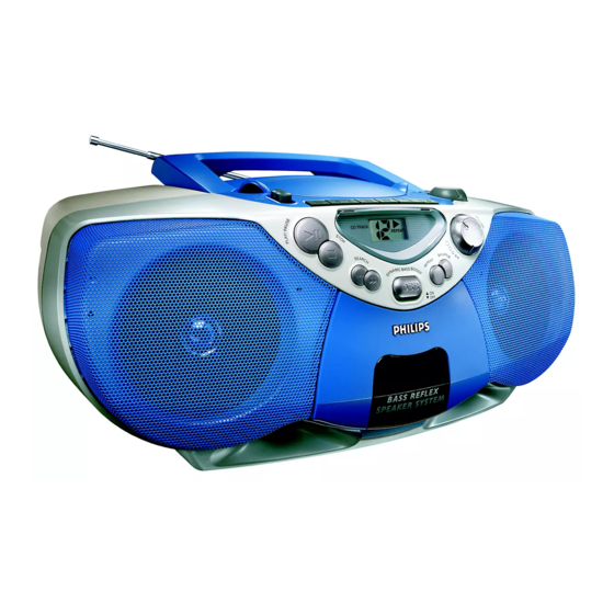
CD Soundmachine
TABLE OF CONTENTS
Technical Specification & Service tools ...........................2 - 1
Service Measurement......................................................2 - 2
Connections and controls....................................3 - 1 to 3 - 2
Block Diagram .................................................................4 - 1
Wiring Diagram ................................................................5 - 1
Circuit diagram ........................................................6 - 1
layout diagram.........................................................6 - 1
Tuner Board
circuit diagram .........................................................7 - 1
layout diagram.........................................................7 - 2
adjustment table ......................................................7 - 2
©
Copyright 2001 Philips Consumer Electronics B.V. Eindhoven, The Netherlands
All rights reserved. No part of this publication may be reproduced, stored in a retrieval
system or transmitted, in any form or by any means, electronic, mechanical, photocopying,
or otherwise without the prior permission of Philips.
Published by LX 0218 Service Audio
Printed in The Netherlands
Subject to modification
circuit diagram .........................................................8 - 1
layout diagram.........................................................8 - 2
adjustment...............................................................8 - 2
layout diagram.............................................9 - 3 to 9 - 4
Exploded view diagram - cabinet...................................10 - 1
Exploded view diagram - tape deck ..............................10 - 2
Mechanical partslist .......................................................10 - 2
Electrical partslist ............................................11 - 1 to 11 - 6
AZ 1080
AZ 1081
all versions
CLASS 1
LASER PRODUCT
3140 785 32020
©
Advertisement
Table of Contents

Related Manuals for Philips AZ 1080


Summary of Contents for Philips AZ 1080
-
Page 1: Table Of Contents
LASER PRODUCT © Copyright 2001 Philips Consumer Electronics B.V. Eindhoven, The Netherlands All rights reserved. No part of this publication may be reproduced, stored in a retrieval system or transmitted, in any form or by any means, electronic, mechanical, photocopying, or otherwise without the prior permission of Philips. -
Page 2: Handling Chip Components
1 - 1 HANDLING CHIP COMPONENTS © ñ WARNING WAARSCHUWING All ICs and many other semiconductors are susceptible to Alle IC´s en vele andere halfgeleiders zijn gevoelig voor electrostatic discharges (ESD). Careless handling during electrostatische ontladingen (ESD). repair can reduce life drastically. Onzorgvuldig behandelen tijdens reparatie kan de levensduur When repairing, make sure that you are connected with the drastisch doen vermindern. -
Page 3: Technical Specifications
2 - 1 TECHNICAL SPECIFICATIONS GENERAL TUNER - AM SECTION Mains voltage -/00/05/14 : 230 V Tuning range : 512 - 1635 kHz -/10 : 240 V : 468 kHz ± 3 kHz IF frequency -/01 : 120 / 230 V 1500 µV/m at 26dB S/N Sensitivity Mains frequency -/00/05/10/14 : 50 Hz... -
Page 4: Service Measurement
2 - 2 SERVICE MEASUREMENT Bandpass Tuner SW LF Voltmeter 250Hz-15kHz Aerial replacement e.g. PM2534 e.g. 7122 707 48001 RF Generator Capacitor e.g. PM5326 S/N and distortion meter e.g. Sound Technology ST1700B To avoid atmospheric interference all AM-measurements have to be carried out in a Faraday«s cage. Use a bandpass filter (or at least a high pass filter with 250Hz) to eliminate hum (50Hz, 100Hz). -
Page 5: Connections And Controls
3 - 1 CONNECTIONS AND CONTROLS... - Page 6 3 - 2...
-
Page 7: Block Diagram
4 - 1 4 - 1 BLOCK DIAGRAM +TUNER ATM5 2 BAND TUNER +A +A_ON ECO-MTF-SD POWER AMP ROTARY VOLUME TAPE MODULE TA8227P TAPE 8 OHM LOUDSPEAKER +A_ON CD MX Control panel TRANSFORMER +A_ON RECTIFIER 1N4003 +TUNER 1N4003 TAPE TAPE 1.5 V X 6... -
Page 8: Wiring Diagram
5 - 1 5 - 1 WIRING DIAGRAM BATTERY COMPARTMENT 8254 CD DOOR SW CD DRIVE MITSUMI MCD1B PH-B 8801 8803 8802 8253 1256 PH-B 1802 +BATT PH-B FOR /01/11 ONLY DOOR_SW 1804 VOLTAGE SELECTOR EH-B 0200 1255 EH-B 1801 8000 FMZ-ST (For MITSUMI MCD1B only) -
Page 9: Front Board Circuit Diagram
6 - 1 6 - 1 FRONT BOARD - CIRCUIT DIAGRAM FRONT BOARD - LAYOUT DIAGRAM 1250 E1 1251 C4 1400 B1 1401 B1 1402 B1 1403 B2 7403 REPEAT 1404 C2 THD5064 1405 C1 SHUFFLE 1406 A4 2250 D2 2251 F2 2252 E2 1 2 3 4 5 6 7... - Page 10 7 - 1 7 - 1 TUNER BOARD (ATM-5) - CIRCUIT DIAGRAM 1001 A4 1104 E3 1110 B11 5107a 5107b 5107c 2101 A4 SFE10.7MS3 SFE10.7MS2 CDA10.7MC1 T003 All SMD Transistors 2102 A4 1001 FM-RF 180KHz 230KHz 2103 D4 2104 G7 2105 A5 2106 F10 7102...
-
Page 11: Layout Diagram
7 - 2 7 - 2 TUNER BOARD (ATM-5) - LAYOUT DIAGRAM TUNER ADJUSTMENT TABLE Waverange Input Frequency Input Set tuned to Adjust Measure on Scope / Counter 1001 E 1 5104 OSCILLATOR 1104 A 2 5105 1110 F 6 5106 1104 2103 D 2... -
Page 12: Recorder Board Circuit Diagram
8 - 1 8 - 1 RECORDER BOARD- CIRCUIT DIAGRAM 1707 C 3 1709 A14 2706 B 4 2711 F 6 2719 C 8 2727 F 7 2733 H13 2750 D 6 3703 D 3 3712 E 7 3720 F 7 3730 F12 3743 C 9 3761 G 6... -
Page 13: Layout Diagram
8 - 2 8 - 2 RECORDER BOARD - LAYOUT DIAGRAM 71 A 1 2729 C 5 3733 B 2 9756 C 3 72 D 5 2730 D 1 3734 D 5 9757 D 3 73 A 5 2731 C 1 3735 D 3 9759 D 4 74 A 1... -
Page 14: Combi Boad Circuit Diagram
9 - 1 9 - 1 COMBI BOARD (CONTRAL / CD PART ) - CIRCUIT DIAGRAM L H14 3851 A1 R H14 3852 B1 +A G14 3853 C3 5V G14 3854 C2 0100 F8 CONTROL / CD PART 3855 C2 0200 G9 3856 B2 1801 A1... - Page 15 9 - 2 9 - 2 COMBI BOARD (Audio part) - CIRCUIT DIAGRAM L F14 1252 B3 1256 G5 2254 C10 2258 B12 2262 C13 2267 H11 2271 G6 2276 D9 2281 C11 3258 C4 3262 A4 3266 C11 3270 E8 3277 G10 3286 E6 3292 B4...
- Page 16 9 - 3 9 - 3 COMBI BOARD (Solder Side) - LAYOUT DIAGRAM 3812 3300 3839 3268 2256 3871 4820 2808 2257 3265 2824 4811 3841 4807 4865 4858 3267 4849 4813 3843 4812 2826 2833 3864 2836 4856 2835 2839 4857 4876...
-
Page 17: Layout Diagram
9 - 4 9 - 4 COMBI BOARD (Componet Side) - LAYOUT DIAGRAM LOUDSPEAKER BOARD - LAYOUT DIAGRAM CD DOOR SWITCH - LAYOUT DIAGRAM... -
Page 18: Exploded View Diagram - Cabinet
10 - 1 10 - 1 EXPLODED VIEW DIAGRAM - CABINET 10 (2x) 38 37 36 35 50 63 27 18... -
Page 19: Exploded View Diagram - Tape Deck
10 - 2 10 - 2 MECHANICAL PARTSLIST - CABINET EXPLODED VIEW DIAGRAM - TAPE DECK AZ1080 AZ1081 3140 114 44770 Cass Door 3140 114 45120 Cass Door 3140 114 44760 Cass Door Lens 3140 114 44760 Cass Door Lens 3140 114 38750 Pointer 3140 114 45080... - Page 20 11 - 1 11 - 1 ELECTRICAL PARTSLIST - FRONT BOARD ELECTRICAL PARTSLIST - TUNER BOARD (ATM5-2B) - MISCELLANEOUS - - RESISTORS - - MISCELLANEOUS - - COILS & FILTERS - 1110 4822 267 10954 CONNECTOR 5-PINS 5101 4822 157 70513 FM RF COIL 1250 9965 000 07513...
-
Page 21: Electrical Partslist
11 - 2 ELECTRICAL PARTSLIST - RECORDER BOARD (ECO-MTF) - MISCELLANEOUS - - RESISTORS - 1707 4822 277 11504 PUSH SWITCH 6P2T 3727 4822 116 52256 2,2K 5% 0,5W 1725 4822 265 11207 CONNECTOR 6-PINS 3730 4822 116 83868 150R 5% 0,5W 3731 4822 116 52291 56K 5% 0,5W... - Page 22 11 - 3 ELECTRICAL PARTSLIST - COMBI BOARD (CD PART) - MISCELLANEOUS - - CAPACITORS - 1801 2422 025 17389 CONNECTOR 16-PINS 2858 4822 124 40207 100µF 20% 25V 1803 4822 267 10732 CONNECTOR 12-PINS 2859 4822 124 81151 22µF 20% 50V 1806 4822 276 12889 MICRO SWITCH...
- Page 23 11 - 4 ELECTRICAL PARTSLIST - COMBI BOARD (CD PART) - RESISTORS - - RESISTORS - 3844 4822 051 20822 8,2K 5% 0,1W 4853 4822 051 20008 0R JUMPER (0805) 3845 4822 051 10102 1K 2% 0,25W 4854 4822 051 20008 0R JUMPER (0805) 3846 4822 117 10361...
- Page 24 11 - 5 ELECTRICAL PARTSLIST - COMBI BOARD (AUDIO PART) - COILS & MISCELLANEOUS - - RESISTORS - 1252 4822 267 10731 CONNECTOR 6-PINS 3274 4822 051 30151 150R 5% 0,062W 1254 4822 267 10958 CONNECTOR 5-PINS 3275 4822 116 52176 10R 5% 0,5W 1257 2422 127 00538...
- Page 25 11 - 6 ELECTRICAL PARTSLIST - MISCELLANEOUS - MISCELLANEOUS - 1005 2422 264 00428 LOUDSPEAKER 8R 3W 1006 2422 264 00428 LOUDSPEAKER 8R 3W 1007 3140 118 33100 TRANSF. MAINS 230V 1007 3140 118 33110 TRANSF. MAINS 110/220V 1009 2422 030 00333 MAINS SOCKET 1009 4822 265 20318...