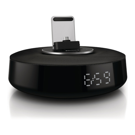
Philips AS111 series Service Manual
For android
Hide thumbs
Also See for AS111 series:
- User manual (26 pages) ,
- Quick start manuals (4 pages) ,
- Quick start manual (2 pages)
Table of Contents
Advertisement
Quick Links
See also:
User Manual
for Android Docking speaker
TABLE OF CONTENTS
Version variation...........................................................1-2
Safety Instructions.................................................2-1..2-3
Set Block diagram.........................................................3-1
Set Wiring diagram........................................................4-1
Disassembly diagram ............................................... ...5-1
Circuit diagram.......................................................6-1..6-2
Layout diagram......................................................6-3..6-6
Mechanical Exploded view............................................7-1
Copyright 2011 Philips Consumer Electronics B.V. Eindhoven, The Netherlands
©
All rights reserved. No part of this publication may be reproduced, stored in a retrieval system or
transmitted, in any form or by any means, electronic, mechanical, photocopying, or otherwise without
the prior permission of Philips.
Published by LX 1145 Service Audio
Version 1.0
Printed in The Netherlands
Subject to modification
Page
AS111/
all
3141 785 37020
Advertisement
Table of Contents

Related Manuals for Philips AS111 series


Summary of Contents for Philips AS111 series
- Page 1 Android Docking speaker AS111/ TABLE OF CONTENTS Page Version variation............1-2 Safety Instructions..........2-1..2-3 Set Block diagram............3-1 Set Wiring diagram............4-1 Disassembly diagram ..........5-1 Circuit diagram............6-1..6-2 Layout diagram............6-3..6-6 Mechanical Exploded view..........7-1 Copyright 2011 Philips Consumer Electronics B.V. Eindhoven, The Netherlands © All rights reserved. No part of this publication may be reproduced, stored in a retrieval system or transmitted, in any form or by any means, electronic, mechanical, photocopying, or otherwise without the prior permission of Philips. 3141 785 37020 Published by LX 1145 Service Audio Printed in The Netherlands Subject to modification Version 1.0...
-
Page 2: Class 1 Laser Product
2.0 SAFTETY INSTRUCTIONS WAARSCHUWING WARNING Alle IC’s en vele andere halfgeleiders zijn All ICs and many other semi-conductors are gevoelig voor electrostatische ontladingen susceptible to electrostatic discharges (ESD). (ESD). Careless handling during repair can reduce life Onzorgvuldig behandelen tijdens reparatie kan drastically. -
Page 3: Esd Protection
2.1 ESD PROTECTION When the power supply is being turned on, you may not remove this laser cautions label. If it removes, radiation of laser may be received. PREPARATION OF SERVICING Pickup Head consists of a laser diode that is very susceptible to external static electrocity. Although it operates properly after replacement, if it was subject to electrostatic discharge during replacement, its life might be shortened. -
Page 4: Safty Precautions
SAFTY NOTICE SAFTY PRECAUTIONS LEAKAGE CURRENT CHECK Plug the AC line cord directly into a 120V AC outlet (do Measure the AC voltage across the 1500 resistor. not use an isolation transformer for this check). Use an The test must be conducted with the AC switch on and AC voltmeter, having 5000 per volt or more sensitivity. -
Page 5: Block Diagram
BLOCK DIAGRAM... -
Page 6: Wiring Diagram
WIRING DIAGRAM... - Page 7 BOTTOM CAB. REAR CAB. FRONT CAB. SPK BOX BOTTOM...
-
Page 8: Circuit Diagram - Main Board
CIRCUIT DIAGRAM - MAIN BOARD... - Page 9 CIRCUIT DIAGRAM - KEY BOARD USB_L C144 C148 C150 C146 C149 100P C135 C134 FILT 100U/6V3 VOL- MCLK MCLK AOUTL LRCK L22 FB1K D3V3 LRCK BCLK USB_R ET4344 R112 SCLK Sector NC U-SDAT BL-SET NA 1 SDIN AOUTR COW3 R113 C145 LED1 C147...
- Page 10 LAYOUT DIAGRAM - MAIN BOARD TOP SIDE...
- Page 11 LAYOUT DIAGRAM - MAIN BOARD BOTTOM SIDE...
- Page 12 LAYOUT DIAGRAM - KEY BOARD...
- Page 13 LAYOUT DIAGRAM - USB/LED BOARD...
-
Page 14: Exploded View
EXPLODED VIEW...