
Related Manuals for HP J9666A


Summary of Contents for HP J9666A
- Page 1 HP Advanced Services zl Module with Microsoft® Windows Server® 2008 R2 Quick Start Guide...
- Page 2 Server® 2008 R2 (J9666A) by Hewlett-Packard. Software Credits and Notices Warranty SSL used in the HP Services zl Module operating system is See the Customer Support/Warranty booklet included with based on the OpenSSL software toolkit. This product the product. includes software developed by the OpenSSL Project for use A copy of the specific warranty terms applicable to your in the OpenSSL Toolkit.
-
Page 3: Table Of Contents
HP Customer Support Services ........ - Page 4 B Waste Electrical and Electronic Equipment (WEEE) Statements C Hardware Components Front Panel Buttons, LEDs, and Connectors ......C-1 Internal Ports .
-
Page 5: Hardware Installation
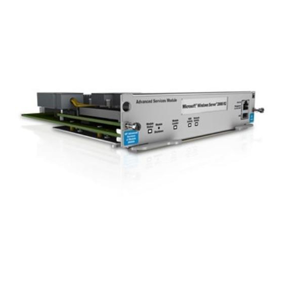
4GB of DDR3 memory. The server software on the HDD is prelicensed. You install the Advanced Services Module with Microsoft Windows Server 2008 R2 in an HP E5400 zl or E8200 zl Series switch. The module automatically boots to the Windows Server 2008 R2 OS. - Page 6 Module Status Figure 1-1. Module Front Panel Additional information about installing and using the module is provided in the HP Advanced Services zl Module with Microsoft Windows Server 2008 www.hp.com/ R2 Installation and Getting Started Guide, which is available at...
-
Page 7: Install The Module
Check the temperature specifications for the module; different modules have different temperature requirements. The module is hot-swappable; that is, the HP zl switch can be powered on or off when you install the module within it. The following procedure assumes the switch is powered on. -
Page 8: Installation Procedure
Hardware Installation Install the Module Installation Procedure Use a Torx T-10 or flat-bladed screwdriver to unscrew the screws in the cover plates over the slot where you will install the module. Store the cover plates for possible future use. Hold the module by its bulkhead, taking care not to touch the metal connectors or components on the board. -
Page 9: Verifying That The Module Is Installed Correctly
Install the Module Verifying That the Module Is Installed Correctly If you have installed the module in a powered off HP zl switch, power up the switch. After the switch powers up, the module will begin to power up. If you have installed the module in a powered on switch, the module begins to power up immediately. -
Page 10: Environmental Specifications
*Notes on the Advanced Services Module operating temperature: Operate at 50°C The Advanced Services Module can operate in an HP E5406 zl or E5412 zl switch at up to 50°C if you install all Advanced Services Modules on the left side of the chassis (when you face the front, or port side, or the switch). - Page 11 Hardware Installation Environmental Specifications Figure 1-3. HP E5412 zl chassis module slots...
- Page 12 Hardware Installation Environmental Specifications...
-
Page 13: Getting Started
If you do not know the module’s IP address and do not have a physical connection to it, you can connect to the module CLI through the HP zl switch CLI. Then you can see the IP address that the module has been assigned through DHCP, or you can assign the module a static IP address. - Page 14 The module has two internal ports. The instructions above apply to port 2. You must never disable this interface (<slot>2) from the HP zl switch CLI. Other- wise, the module will fault. It is also recommended that you do not disable...
-
Page 15: Next Steps
After you establish the RDP connection, you can begin to manage the server, changing its IP address (if necessary), joining it to the domain, and adding roles to it. The HP Advanced Services zl Module with Microsoft Windows Server 2008 R2 Installation and Getting Started Guide provides you with... - Page 16 Getting Started Next Steps...
-
Page 17: Troubleshooting
• Disabling the module’s internal port 2 can also cause this problem. – In the HP zl switch CLI, enter interface <slot>2 and enable. – If this command does not fix the problem, and you cannot access neither the module CLI nor can you reach the server running on the module, you must access the module’s Special Administration... -
Page 18: Hp Customer Support Services
<slot>2 and enable. HP Customer Support Services HP offers support 24 hours a day, seven days a week through the use of a number of automated electronic services. See the Customer Support/Warranty booklet that came with the product for information on how to use these services to get technical support. -
Page 19: A Emc Regulatory Statements
EMC Regulatory Statements EMC Regulatory Statements U.S.A. - FCC Class A This equipment has been tested and found to comply with the limits for a Class A digital device, pursuant to Part 15 of the FCC Rules. These limits are designed to provide reasonable protection against interference when the equipment is used in a commercial environment. -
Page 20: Japan - Vcci Class A
Japan - VCCI Class A Korea Taiwan European Community Declaration of Conformity This product is designed for operation with the HP ProCurve switches that have zl module slots. Refer to the Declarations of Conformity included in the Installation Guides for those products. -
Page 21: B Waste Electrical And Electronic Equipment (Weee) Statements
Waste Electrical and Electronic Equipment (WEEE) Statements Waste Electrical and Electronic Equipment (WEEE) Statements Disposal of Waste Equipment by Users in Private Household in the European Union This symbol on the product or on its packaging indicates that this product must not be disposed of with your other household waste. - Page 22 Waste Electrical and Electronic Equipment (WEEE) Statements Laitteiden hävittäminen kotitalouksissa Euroopan unionin alueella Jos tuotteessa tai sen pakkauksessa on tämä merkki, tuotetta ei saa hävittää kotitalousjätteiden mukana. Tällöin hävitettävä laite on toimitettava sähkölaitteiden ja elektronisten laitteiden kierrätyspisteeseen. Hävitettävien laitteiden erillinen käsittely ja kierrätys auttavat säästämään luonnonvaroja ja varmistamaan, että...
- Page 23 Waste Electrical and Electronic Equipment (WEEE) Statements Smaltimento delle apparecchiature da parte di privati nel territorio dell'Unione Europea Questo simbolo presente sul prodotto o sulla sua confezione indica che il prodotto non può essere smaltito insieme ai rifiuti domestici. È responsabilità dell'utente smaltire le apparecchiature consegnan- dole presso un punto di raccolta designato al riciclo e allo smaltimento di apparecchiature elettriche ed elettroniche.
- Page 24 Para obter mais informações sobre locais que reciclam esse tipo de material, entre em contato com o escritório da HP em sua cidade, com o serviço de coleta de lixo ou com a loja em que o produto foi adquirido.
-
Page 25: C Hardware Components
Hardware Components Front Panel Buttons, LEDs, and Connectors Hardware Components Front Panel Buttons, LEDs, and Connectors This section describes the different buttons, LEDs, and connectors on the front panel of a module: ■ Module Shutdown button—This button is used to shut down the module. - Page 26 Hardware Components Front Panel Buttons, LEDs, and Connectors Table C-1. Module LEDs Module LED State Meaning Module When the module is first installed, this LED follows the Status (green/ following sequence: orange) 1. Green for ~15s - The module has power. 2.
-
Page 27: Internal Ports
C a u t i o n Do not disable the <slot>2 port. If you do, the communications between the HP zl switch and the SBM will fail, causing first the module to fail and then the switch to report the SBM as a malfunctioning module. - Page 28 Hardware Components Serial Numbers Disk drive serial and product numbers Figure C-1. Locating the disk drive serial number The serial number for the module is located on the back left corner of the module (Figure C-2). Module serial number SN: SGxxxxxxxx Figure C-2.
-
Page 29: Switch Leds
Hardware Components Switch LEDs Switch LEDs The following figures show the Test, Fault, and Module Status LEDs on the switches the module can be installed in. Test LED Module Status LEDs Fault LED Figure C-3. Test, Fault, and Module Status LEDs on an E5400 zl Series switch Test LED Module Status LEDs Fault LED... -
Page 30: Replacing Or Removing A Module
Hardware Components Replacing or Removing a Module Replacing or Removing a Module It is highly recommended that the module be shutdown before replacing or removing it. The module maybe shutdown using the shutdown button on the front panel of the module or using the following CLI command: hostswitch# services <slot-id>... -
Page 31: Replacing Field Replaceable Units (Frus
This module includes the following FRUs: ■ Disk Drive Compact flash ■ Please see the HP Advanced or Extended Services zl Modules Field Replace- able Units (FRU) Guide, which you can view or print from the HP networking Web site (www.hp.com/networking/support). - Page 32 Hardware Components Replacing Field Replaceable Units (FRUs)
-
Page 33: D Software Components
The HP Advanced Services zl Module with Microsoft® Windows Server® requires switch software version K.14.65 or later to be installed in the switch. Version K.15.03 or greater is recommended if the module is installed in an HP E8200 zl switch with dual management modules. K.15.03 will gracefully shut- down and restart the module in the event of a management module failover. -
Page 34: Updating The Service Os
The module uses FTP to download its software. This requires that a local FTP server must be setup. The software update from HP is packaged as a “zip” file containing a top-level folder which needs to be extracted onto the FTP server so that the folder name is visible to download from the module CLI. -
Page 35: Updating Service Os Via Usb
Software Components Updating the Service OS hostswitch(svcs-mod-C:SvcOS)# show images Update the Service OS. hostswitch(svcs-mod-C:SvcOS)# update ServiceOS <Service OS image> Boot the Service OS (optionally, boot the AppSW): hostswitch(svcs-mod-C:SvcOS)# boot ServiceOS Changing boot from CF Service OS to Service OS. System will be rebooted. Do you want to continue [y/n]? y Rebooting Check the version of the updated Service OS and confirm it is running: hostswitch(svcs-mod-C:SvcOS)# show version... -
Page 36: Device Disable
Software Components Device Disable Unmount the USB flash drive. hostswitch(ssvcs-mod-C:SvcOS)# usb unmount 10. Remove the USB flash drive from the module. 11. For the rest of the procedure, go to Step 4. on page D-2. Device Disable The module offers improved security and reliability. In case there is no physical security on the chassis, the USB and the shutdown button can be disabled to prevent unauthorized or undesired access. - Page 37 Index HDD Activity … C-2 Meaning … C-2 CLI Command Module Locator … C-2 boot ONE-app … D-3 Module Status … 1-5, C-2 shutdown … C-1, C-6 Network Activity … C-2 Command Line Interface (CLI) … 1-1 State … C-2 show version …...
- Page 38 USB slot SBM … C-1 VLAN … 2-1 warranty … 1-1 Waste Electrical and Electronic Equipment (WEEE) Statements … B-1 WinPcap caution … 2-3 zl Switch … 1-3, 1-5, C-5 2 – Index...
- Page 39 center Connection Manager Controller Management and Configuration...
- Page 40 To learn more, visit www.hp.com/networking © Copyright 201 1 Hewlett-Packard Development Company, L.P. The information contained herein is subject to change without notice. The only warranties for HP products and services are set forth in the express warranty statements accompanying such products and services.