Panasonic DP-C405 Service Handbook
Digital color imaging systems
Hide thumbs
Also See for DP-C405:
- Operating instructions manual (100 pages) ,
- Service manual (921 pages) ,
- Scan/email manual (62 pages)
Table of Contents
Advertisement
Quick Links
This service information is designed for experienced repair technicians only and is not intended for use by the general public.
It does not contain warnings or cautions to advise non-technical individuals of potential dangers in attempting to service a product.
Products powered by electricity should be serviced or repaired only by experienced professional technicians. Any attempt to service
or repair the product or products dealt within this service information by anyone else could result in serious injury or death.
Digital Color Imaging Systems
DP-C405 / C305 / C265
WARNING
© 2008 Panasonic Communications Co., Ltd.
All rights reserved. Unauthorized copying and distribution is
a violation of law.
Order Number: MGCS071203C0
[ Version 1.1 ]
H21
Advertisement
Table of Contents
Troubleshooting

Related Manuals for Panasonic DP-C405


Summary of Contents for Panasonic DP-C405
- Page 1 Order Number: MGCS071203C0 Digital Color Imaging Systems DP-C405 / C305 / C265 [ Version 1.1 ] WARNING This service information is designed for experienced repair technicians only and is not intended for use by the general public. It does not contain warnings or cautions to advise non-technical individuals of potential dangers in attempting to service a product.
-
Page 4: Important Notice
* The specifications are subject to change without notice. Panasonic Communications Co., Ltd. reserves the right to make improvements in the product design without reservation and without notice. - Page 6 For PB and Other destinations, not for PU (USA/Canada)
- Page 7 Unpacking Caution Do not lift the Paper Transport Unit by the PC Board, as damage to the PC Board will occur. Make sure to lift the Paper Transport Unit as shown in the illustrations below. Note: Refer to the Installation Instructions when installing the Unit.
-
Page 8: For Your Safety
Precautions For Your Safety To prevent severe injury and loss of life, read this section carefully before servicing the Panasonic machine to ensure proper and safe operation of your machine. Please ensure that the machine is installed near a wall outlet and is easily accessible. -
Page 9: Operating Safeguards
Once a month, unplug the machine and check the power cord for the following. If you notice any unusual condition, contact your authorized Panasonic dealer The power cord is plugged firmly into the receptacle. The plug is not excessively heated, rusted, or bent. - Page 10 CAUTION Operating Safeguards Do not place a magnet near the safety switch of the machine. A magnet can activate the machine accidentally, resulting in injuries. Do not use a highly flammable spray, or solvent near the machine. It can cause fire. When copying a thick document, do not use excessive force to press it against the scanning glass.
- Page 14 memo...
-
Page 15: Table Of Contents
2.24. ADF PC Board ........216 1.2. Fax, Printer and Internet Fax Functions .28 2.25. SCN PC Board ........233 1.3. System Combination for DP-C405 Series.........39 2.26. AFE PC Board........239 1.4. Options and Supplies for 2.27. ADU PC Board ........252 DP-C405 Series........40 2.28. - Page 16 Table of Contents 5.16. IH Unit...........586 6.5. 1-Bin Finisher (5/6)....... 676 5.17. Hopper Unit...........588 6.6. 1-Bin Finisher (6/6)....... 680 5.18. Developer Unit ........592 Exploded View & Parts List of 5.19. OPC Unit..........596 1-Bin Saddle-Stitch Finisher 5.20. Toner Waste Container......600 (DA-FS405) ........... 683 5.21.
-
Page 17: Specifications Table
Multi Function 1 Copy Function : PCL6 2 Printer Function Option : PS3 DP-C354 / C264 Std : Mono / DP-C405 / DP-C322 / Color 3 Scanner Function C305 / C265 C262 (Network only) Std : Mono / Option :... - Page 18 Bypass Envelope 12 Warm-up Time Color Approx. 15 sec. 68 °F (20 °C) Mono 13 First Copy Time Color DP-C405 / DP-C354 / Approx. 10.3 sec. C305 / C265 C264 From Platen / LT / A4 Portrait DP-C323 / DP-C322 / Approx.
- Page 19 DP-C405/C305/C265 Description Items Remarks DP-C405 (DP-C354 (DP-C322 Series Series) Series) Mono Up to 40 cpm DP-C405 Up to 35 cpm DP-C354 Up to 32 cpm DP-C323 DP-C322 LT / A4, from Paper Tray exit to Inner Tray Up to 30 cpm...
- Page 20 DP-C405/C305/C265 Description Items Remarks DP-C405 (DP-C354 (DP-C322 Series Series) Series) 25 Multi Copy Range 999 sheets 26 Memory Main Memory DP-C354 / C264-PU 512 MB Std. 512 MB 256 MB DP-C323 / (SC PCB) C263 / C213- 256 MB 512 MB 512 MB Max.
- Page 21 DP-C405/C305/C265 Description Items Remarks DP-C405 (DP-C354 (DP-C322 Series Series) Series) 27 Paper Stack Capacity Inner Tray LTR : 24 lb / A4 : 90 g/m Std. 250 sheets These numbers may vary with the kind of paper used With Paper Transport...
- Page 22 DP-C405/C305/C265 Description Items Remarks DP-C405 (DP-C354 (DP-C322 Series Series) Series) 7 Counter Key Counter Capability Supplied as a Service Part Mechanical Total Counter for USA/Canada etc. 8 Memory Page Memory 256 MB 128 MB x 2 For Fax/Internet Fax SD Memory Card 96 MB Memory, Counter &...
- Page 23 DP-C405/C305/C265 Description Items Remarks DP-C405 (DP-C354 (DP-C322 Series Series) Series) Max 12 Images with HDD Image Overlay (12 Images) Yes (1 Image) Option (HDD: Std.) Image Repeat Others (Inverting ADF & ADU) → LTR x 2 2-Page Copy Mode →...
- Page 24 DP-C405/C305/C265 Description Items Remarks DP-C405 (DP-C354 (DP-C322 Series Series) Series) Job Completion Notice Proof Copy Mode Function Mode Interrupt Electronic Counter Digital Sky Shot Mode Manual Skyshot Mode 3 Control Panel Display Color VGA Touch Panel LCD GREEN: Data & Active Status Lamp RED/Yellow: Caution &...
- Page 25 DP-C405/C305/C265 Description Items Remarks DP-C405 (DP-C354 (DP-C322 Series Series) Series) Error Code Finishing Warning Indicators Add Toner Yes (Each Color) Drum Yes (Each Color) Toner Waste Container Full 0% and less than 10%, 50%, Paper Indicator 100% Add Paper (Under 50 sheets)
- Page 26 ADF Productivity (LTR / i-ADF 100% ADU Copy Productivity (LTR / A4) Transport Method Stack less 1→2 (Color) DP-C405 / C305 45% or more 1 copy 50% or more Approx. 60% DP-C265 Throughput 50% or more When exiting to lower Inner DP-C405 / Tray;...
- Page 27 DP-C405/C305/C265 Description Items Remarks DP-C405 (DP-C354 (DP-C322 Series Series) Series) 2 Packing Weight Scanner/ i-ADF 407.9 lb USA/Canada only pre-installed Model (185 kg) 127.9 lb Scanner & i-ADF Unit 123.2 lb (56 kg) (58 kg) 313.1 lb Printer Unit 321.2 lb (146 kg)
-
Page 28: Fax, Printer And Internet Fax Functions
DP-C405/C305/C265 1.2. Fax, Printer and Internet Fax Functions 1.2.1. Fax Function Description Items Remarks DP-C405 (DP-C354 (DP-C322 Series Series) Series) Main Specifications 1 Compatibility ITU-T Std. & Non-Std. 2 PSTN Line Port 1-Line only 3 Leased Line Port 4 V.24 Line Port 5 Modem Speed 33.6 - 2.4kbps... - Page 29 DP-C405/C305/C265 Description Items Remarks DP-C405 (DP-C354 (DP-C322 Series Series) Series) 5 Document Size (Max.) ADF: LDR / A3 6 Effective Scanning Width LDR :10.8 in (274 mm) / A3 : (292 mm) 7 A3 Size TX/RX Conforms to ITU-T A3...
- Page 30 DP-C405/C305/C265 Description Items Remarks DP-C405 (DP-C354 (DP-C322 Series Series) Series) 6 Max. Station Name Characters 7 Full Number Dialing Max. 70 stations (Buffered Dialing) 8 Direct Dialing Voice mode (Monitor Dialing) Default setting is up to 5 times at 3 min. intervals,...
- Page 31 DP-C405/C305/C265 Description Items Remarks DP-C405 (DP-C354 (DP-C322 Series Series) Series) 16 Duplex Scanning 17 Multi-Station Selection Prohibition 18 Confirmation of Selected Station 19 Direct Dial Prohibition 20 Direct Dial Re-entering Reception Features 1 Substitute Reception LTR/A4/LGL: 70 - 100% 2 Fixed Reduction (in 1% Steps), Top &...
- Page 32 DP-C405/C305/C265 Description Items Remarks DP-C405 (DP-C354 (DP-C322 Series Series) Series) 4 Comm. Journal With Image Data 5 Last Ind. XMT Journal List Printouts 1 One-Touch List 2 ABBR. No. List 3 Program List 4 Address Book Search List Auto Dialer List...
- Page 33 DP-C405/C305/C265 1.2.2. Printer Function Description Items Remarks DP-C405 (DP-C354 (DP-C322 Series Series) Series) Interface 1 Centronics Parallel I/F 2 LAN (Network) Ethernet 10Base-T / 100Base-TX USB 2.0 High/Full Speed 3 USB Port Support 4 IEEE-1394 Firewire Printer Function LDR, LGL, LTR, LTR-R, INV-R For USA/Canada etc.
- Page 34 DP-C405/C305/C265 Description Items Remarks DP-C405 (DP-C354 (DP-C322 Series Series) Series) Custom Size/Postcard Size 11 Duplex Printing is not available. 12 Collation Stack 13 Status Monitor 14 Network Printing 15 Network Status Monitor 16 Smoothing 17 Applicable PC IBM PC, AT or Compatible, MAC MAC is PS only.
- Page 35 DP-C405/C305/C265 1.2.3. Network Scanner Function Description Remarks Items DP-C405 (DP-C354 (DP-C322 Series Series) Series) Interface 1 Centronics Parallel I/F 2 LAN (Network) Ethernet 10Base-T/ 100Base-TX 3 USB Port Port is used for Printing only. 4 IEEE-1394 Firewire Network Scanning Function...
- Page 36 DP-C405/C305/C265 1.2.4. Internet Fax Function Description Items Remarks DP-C405 (DP-C354 (DP-C322 Series Series) Series) Main Specifications 1 Communication Protocols SMTP / POP3 2 Max. Modem Speed 3 Coding Scheme JBIG/MMR/MR/MH 4 File Format TIFF 5 LAN (Network) Ethernet 10Base-T / 100Base-TX Scanner Mechanism 1 Max.
- Page 37 7 DHCP Client Lightweight Directory Access 8 LDAP Protocol Selectable, PDMS / TIFF 9 TIFF Viewer Viewer Certainty Email from RCV side to 1 Comm. Journal (w / Image) Panasonic Internet Fax's only 1 Email Address Ver. 1.1 FEB 2008...
- Page 38 SD Memory Card on the SC PCB (Not the Front Slot) SD Memory Card Formatting Structure and Partitioning by Function SD Memory Card Formatting Structure 128 MB - 4 GB for DP-C405 Series SD Memory Size 64 MB 128 MB - 1 GB for DP-C354/C322 Series Max.
-
Page 39: System Combination For Dp-C405 Series
DP-C405/C305/C265 1.3. System Combination for DP-C405 Series Inverting ADF (i-ADF) ADF PC Board Scanner Unit SCN PC Board Color Panel Scan Memory Main PC Board Network Scanner Module (PNL PC Board) (128 MB x1) (SC PC Board) <On the SC PCB>... -
Page 40: Options And Supplies For Dp-C405 Series
DP-C405/C305/C265 1.4. Options and Supplies for DP-C405 Series 1. Options Option Name Option Number Remarks System Console 1 (Tray x 1) DA-DS320 System Console 2 (Tray x 2) DA-DS321 1-Bin Finisher DA-FS402 DP-C405/C305/C265, and downward compatible with DP-C354/C323/C264/C263/ 1-Bin Saddle-Stitch Finisher DA-FS405 C213 with updated firmware. - Page 41 DP-C405/C305/C265 2. Supplies Remarks Part Name Part Number PB and Other (USA/Canada) Destinations DQ-TUW28K DP-C405 DQ-TUW05K DQ-TUV28K Toner Cartridge (Black) DP-C305/C265 DQ-TUV05K DQ-TUY28K DP-C305/C265 DQ-TUY05K DQ-TUV20C Toner Cartridge (Cyan) DQ-TUV05C DQ-TUV20M Toner Cartridge (Magenta) DP-C405/C305/C265 DP-C405/C305 DQ-TUV05M DQ-TUV20Y Toner Cartridge (Yellow)
- Page 42 DP-C405/C305/C265 3. Option Configuration Ver. 1.1 FEB 2008...
-
Page 43: Options And Supplies For Dp-C354/C322 Series
2. PS3 is a Page Description Language of the Adobe Systems Incorporated. 3. Availability may differ as per destination. Please ask your sales company for detail. 4. Genuine SD Memory Cards depict an SD Logo on their label. (Panasonic's 512 MB Sample is shown below). Ver. 1.1 FEB 2008... - Page 44 DP-C405/C305/C265 2. Supplies Part Name Part Number Remarks DP-C354/C323/C264/C263 Toner Cartridge (Black) DQ-TUS28K Toner Cartridge (Cyan) DQ-TUS20C (Yield is based on 5% coverage, LT/A4, Continuous Print) Toner Cartridge (Magenta) DQ-TUS20M Toner Cartridge (Yellow) DQ-TUS20Y DP-C213 Toner Cartridge (Black) DQ-TUT20K Toner Cartridge (Cyan)
- Page 45 DP-C405/C305/C265 3. Option Configuration Ver. 1.1 FEB 2008...
- Page 46 DP-C405/C305/C265 Ver. 1.1 FEB 2008...
- Page 47 DP-C405/C305/C265 Ver. 1.1 FEB 2008...
-
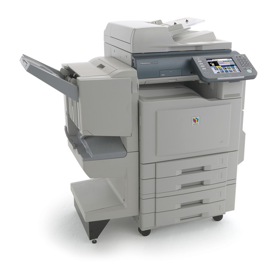
Page 48: External View
DP-C405/C305/C265 1.6. External View 1. Standard Configuration (For USA Only) Complies with FDA radiation performance standards, 21 CFR Subchapter J Manufacturer's Name and Address Factory ID Top View 32.5 in (826mm) 26.1 in (664 mm) Rear View Right View Left View... - Page 49 DP-C405/C305/C265 2. With Optional System Console and Finisher Configuration 1-Bin Finisher (DA-FS402 / FS350 / FS320) Top View 14.84 in (377 mm) Left View Front View Right View Rear View 1-Bin Saddle-Stitch Finisher (DA-FS405 / FS356 / FS325) Top View 26.38 in (670 mm)
- Page 50 DP-C405/C305/C265 3. Space Requirements With Options Main Unit 3.94 in (100 mm) 11.85 in 26.14 in (301 mm) (664 mm) 32.50 in (826 mm) 15.11 in (384 mm) 3.94 in (100 mm) 45.87 in (1165mm) Main Unit + Exit Tray (Outer) 3.94 in (100 mm)
- Page 51 (Letters "I" and "O" are skipped) Model Number and Destination Code (Main Unit) 3-Digit number or alphanumeric representation (Except Letters "I" and "O") For Example: (For USA and Canada) (For UK) = DP-C405-PU = DP-C405-PB = DP-C305-PU = DP-C305-PB = DP-C265-PB = DP-C265-PU = DP-C354-PU...
-
Page 52: Control Panel
DP-C405/C305/C265 1.7. Control Panel Note 1: Model availability may differ as per destination. Please ask your sales company for details. Note 2: LCD Display Brightness Adjustment To adjust the brightness of the LCD display, press and while holding down the “Clear” key, keep pressing the “1”, or the “2”... -
Page 53: Fans
DP-C405/C305/C265 1.8. Fans Toner Bottle Fan IH Driver Fan Pressure Roller Fan IH Fan LVPS Fan Right Cover Fan LSU Fan 1.9. Motors ADF Paper Feed Motor ADF Feed Motor Scanning Motor Drum Motor 1 FTR and LSU Shutter Motor... -
Page 54: Sensors
DP-C405/C305/C265 1.10. Sensors ADF Original Length Sensor 2 (401-03) Platen Cover (ADF) Angle Sensor (401-11) ADF Original Length Sensor 1 (401-04) Platen Cover (ADF) Open Sensor (401-12) ADF Original Width Sensor 2 (401-01) Fuser Unit Sensors (See Figure A) ADF Original Width Sensor 1 (401-02) - Page 55 DP-C405/C305/C265 < Figure A > Fuser Pressure Release Sensor 1 (1819-17) IH Core Sensor 1 Fuser Pressure Release Sensor 2 (1819-16) (DP-C322 Series) IH Core Sensor 2 (DP-C322 Series) Thermistor (HR1) Fuser Entrance Sensor (1819-43) Thermistor (HR3) (DP-C322 Series) Thermistor (HR2)
-
Page 56: Clutches And Switches
Paper Feed Roller Clutch (Tray2) Intermediate Roller Clutch Pickup Roller Solenoid (Tray 3) Intermediate Roller Clutch Paper Feed Roller Clutch (Tray 3) (DP-C405/C305 Only) Pickup Roller Solenoid (Tray 4) Optional Intermediate Roller Clutch Paper Feed Roller Clutch (Tray 4) 1.12. PC Board... -
Page 57: Maintenance, Adjustments And Check Points
DP-C405/C305/C265 2 Maintenance, Adjustments and Check Points 2.1. Preventive Maintenance Preventive maintenance is performed at specific intervals, and consists of machine cleaning, and parts replacement. It is essential to perform these service activities properly, and at the specified intervals for customer satisfaction. - Page 58 DP-C405/C305/C265 2.1.5. Data Security Precautions 1. The Service Mode Password is essential to maintaining the security of the machine. Service technicians must change the factory default password using the Service Mode “F7-14: Service Mode Password”, record the new password and store it in a safe place out of the reach of others.
-
Page 59: Required Tools
DP-C405/C305/C265 2.2. Required Tools Tools Tools Personal Notebook Computer 10 Pliers Cables (USB Cable, Crossover LAN 11 Nipper Cable, etc.) SD Memory Card (128 MB - 1GB) 12 Cutter Soft Cloth 13 Vacuum Cleaner Isopropyl Alcohol 14 Cotton Swab Phillips Screwdriver (#2) -
Page 60: Preventive Maintenance Points
DP-C405/C305/C265 2.3. Preventive Maintenance Points 22, 23 50, 52 38, 39, 40, 41 No. 36, 37 : DP-C405 / C305 Only Ver. 1.1 FEB 2008... -
Page 61: Preventive Maintenance Check List
DP-C405/C305/C265 2.4. Preventive Maintenance Check List The chart outlined below is a general guideline for maintenance. Replacement/ Cleaning Adjustment Mechanical Parts Ref. No. Ref. Counter Cycle Cycle Method Procedure (Sheets) (Sheets) i-ADF Unit Pickup Roller 120K 240K Water Paper Feed Roller... - Page 62 Registration Sensor Dry Cotton Refer to 1918-01 120K Swab Sect 2.2.8. of the Sevice Manual Intermediate Roller Dry Cotton 2130 120K For DP-C405/ Sensor Swab C305 Only Developer Unit Y (Yellow) 480K Refer to F7-02-40-43 M (Magenta) 480K Sect 2.2.11. 5443.
- Page 63 To verify the counter information, print the Total Counter List using the Service Mode: F7 - Electronic Counter - 00 (List Print). 3. Cleaning, Replacement, and Adjustment Cycle (Sheet) are based on using Panasonic's recommended standard paper and supplies. Ratio: Color vs. Black = 2 : 8, LT/A4, 1-Sided, 4 pages/job. These cycles may vary with the kind of paper used, Paper size, orientation, print duty, continuous/interval print and/ or ambient conditions.
-
Page 64: Resetting The P/M (Preventive Maintenance) Counter
DP-C405/C305/C265 2.5. Resetting the P/M (Preventive Maintenance) Counter When the machine reaches the preset P/M Cycle, it will show “Call for P/M” on the LCD Display. The PM Counter can be reset by following the procedures below. 1. Perform the P/M (Preventive Maintenance), refer to sections 2.3. and 2.4. - Page 65 DP-C405/C305/C265 Replace Ref. Ref. Replace Reset Mechanical Parts Cycle Counter Alarm Counter (Sheets) F7-02-52 120K: 24 Cleaning Unit 3418 120K STR Life Alarm Perform “F8-32 STR Counter Count Reset”. Automatic Duplex Unit (Lower) (Machine (F7-02-52 STR Life Count is also...
-
Page 66: Lubrication Point
120K copies or more, however this interval may be reduced due to environmental conditions. 2.7. Easy Maintenance (DP-C405 Series) 2.7.1. Outline This is a new function that stores machine maintenance and machine status history which can be helpful to Service Technicians when performing service maintenance and/or repairs. - Page 67 DP-C405/C305/C265 2.7.3. Procedure 1. Initial Registration when the machine is installed. < Stand by > Stand by < Press"Function"> + <"Copy"> + <"3"> + <Input Password> to enter the Service Mode < Installation Date > < Cancel Confirmation > < Service Mode >...
- Page 68 DP-C405/C305/C265 2. Service History 2.1. Register Service History (Servicing this unit the 1st time of the day) Register required information before exiting the Service Mode. Registration Items: Date of the visit, service details. If the unit is visited the 2nd time on the same day, the visit is treated as a Call Back.
- Page 69 DP-C405/C305/C265 2.2. Register Service History (2nd visit on the unit on the same day) Register required information before exiting the Service Mode. < Service Mode > Confirm that it is a Call Back. If it is a call back, register the Service Action.
- Page 70 DP-C405/C305/C265 2.3. Change Service History Check and/or change registered Service History using < Service Mode F9 > Service Mode F9-23-01. Up to 200 Service History records can be saved. Upon reaching 200 records, as New record is created, the oldest one is automatically deleted.
- Page 71 DP-C405/C305/C265 3. Maintenance Information List Print Print the list for each maintenance function using < Service Mode F9 > Service Mode F9-22. 00 Simulated List: 1 month 01 Simulated List: All 02 Machine Usage List 03 Machine Diagnostic List 04 Maintenance List...
- Page 72 DP-C405/C305/C265 <Print Example (Simulated List) > Select which list to print; either for the last 1 month or All (Last 6 months) F9-22-00 : Simulated List : 1 month F9-22-01 : Simulated List : All Print collective data from each month (1st -last day) Black and Color printing data is collected separately Output paper size and Simulated cover range for A4 or 8.5x11"...
- Page 73 DP-C405/C305/C265 <Print Example (Machine Usage List) > Print Counter Value of Unit using F9 Service Mode F9-22-02 : Machine Usage List. Counter increments by one for each paper feed regardless of paper size. Service Mode printouts are also counted. List Contents:...
- Page 74 DP-C405/C305/C265 <Print Example (Machine Diagnostic List) > F9-22-03 : Machine Diagnostic List Print Jam and Machine error. Print PM unit usage and its estimate replacement time List Contents: (1) Category of Business, Installation Date, and Serial Number (2) Job Error History Top 10 (Paper JAM, Machine Error)
- Page 75 DP-C405/C305/C265 <Print Example (Maintenance List) > F9-22-04 : Maintenance List Print up to 200 Service History Items List Contents: (1) Category of Business, Installation Date&Time, Serial Number, Total Number of Visit, Total Number of Repair (2) Service Date&Time, Service Action, Counter Data If the Service History has been changed, an asterisk (*) is printed before the number.
- Page 76 DP-C405/C305/C265 4. Maintenance Info. Clear < Service Mode F9 > Initialize Maintenance Information: F9-06-08 : Maintenance Info. Clear Items initialized : Counter Data, Service History, Initial Registration Select "RAM Initialize" <"Close"> < F9-06:RAM Initialize > Select "Maintenance <"Close"> Info. Clear"...
- Page 77 DP-C405/C305/C265 5. Maintenance Information Manager 5.1. Change Category of Business < Service Mode F9 > Change the Category of Business that was set during the initial registration using F9-23-03 : Category of Business Category of Business is printed on each list.
- Page 78 DP-C405/C305/C265 5.2. Service History Function Change the Service History Function setting. < Service Mode F9 > Change setting to Yes/No using F9-23-04 : Service History Function When the Service History Function is set to "No", there is no prompting for the registration process before exiting the Service Mode.
- Page 79 DP-C405/C305/C265 6. Structure of Maintenance Function The items for Maintenance Function are located in the F9 Service Mode. • F9 Service Mode (Related Items) F9 Unit Maintenance 06 RAM Initialize 08 Maintenance Info. Clear 22 Print Maintenance Info. 00 Simulated List: 1 month...
-
Page 80: Counter / Parameter Auto Backup
DP-C405/C305/C265 2.8. Counter / Parameter Auto Backup The Counter Information can be backed up by installing an SD Memory Card into the SD Card Slot (CN70) on the SC PC Board. This prevents losing Counter Information due to an error in the System Control (SC) PC Board, or when replacing the SC PC Board. -
Page 81: Counter / Parameter Backup To Sd Card In The Front Slot
The Counter / Parameter Information can also be backed up by installing an SD Memory Card into the Front SD Card Slot. This prevents losing the Counter / Parameter Information when replacing the SC/EC PC Board (New feature for DP-C405 Series). <Backup>... -
Page 82: Power On Display Change (F9-19)
To change the startup Panel Display (when the Power Switch on the Left Side is turned ON) follow the procedure below. This feature is useful if a Dealer wants to personalize the machine with its own company's Logo or Picture (New feature for DP-C405 Series). <Prepare>... -
Page 83: Updating The Firmware (Dp-C405 Series)
DP-C405/C305/C265 2.11. Updating the Firmware (DP-C405 Series) 2.11.1. Firmware Configuration A. Hardware Configuration This machine is controlled by a Main CPU which is located on the System Control (SC) PC Board, and other sub CPUs on the other PCBs. The Firmware of SC PCB, Engine Control (EC) PCB, Scanner Control (SCN) PCB, and Fax Control (FCB) PCB can be updated using a PC, or an SD Memory Card. - Page 84 DP-C405/C305/C265 (2)USB Port The machine's Firmware can be updated using your Notebook PC via an USB Port. This method is convenient when you brought a Notebook PC into the customer's site for the purpose of updating the firmware. Refer to the Firmware Update Operating Instructions, and Section 2.11.3. for additional details.
- Page 85 4) Upgrading the Main Unit's Firmware Code Start the Network Firmware Update Tool, and select the following Parent Firmware File Folder in the C:\Panasonic\Panasonic-FUP\Data folder. The Firmware Type window appears, and proper Firmware Files are selected automatically by selecting the Firmware Type.
- Page 86 Firmware Code File: C405_C305_C265_xx_xxxxxxxx_xx.exe Firmware Data Folder: C:\ Panasonic \ Panasonic-FUP \ Data 3) Preparing the Main Unit for the Firmware Upgrade Before starting, print the F5/F6 Parameters List (Copy Service Mode F9-03-00). Important: DO NOT connect the USB Cable yet.
- Page 87 4) Upgrading the Main Unit's Firmware Code Start the Local Firmware Update Tool, and select the following Parent Firmware File Folder in the C:\Panasonic\Panasonic-FUP\Data folder. The Firmware Type window appears, and proper Firmware Files are selected automatically by selecting the Firmware Type.
- Page 88 Firmware Code File: C405_C305_C265_xx_xxxxxxxx_xx.exe Firmware Data Folder: C:\ Panasonic \ Panasonic-FUP \ Data 3) Preparing the Master Firmware SD Memory Card 1. Insert the SD Memory Card (128 MB to 4 GB) into the SD Memory Card Slot. 2. Perform the SD Memory Card Firmware Writing Tool.
- Page 89 DP-C405/C305/C265 The SD Memory Card is now ready to use for firmware update. (Refer to the SD Memory Card Firmware Writing Tool Readme File.) 2.11.6. Notice after installing the HDD option After the Hard Disc Drive Unit is installed, to prevent a Disc Scan Function from being performed (similar to when the power is abruptly interrupted to the PC), it is important to follow the step sequence below when turing OFF the Power Switches on the machine.
- Page 90 Firmware Type A : Standard D : PS Option Model Number CMFP1_SC : DP-C322/C262 CMFP2_SC : DP-C354/C323/ C264/C263/C213 CMFP25SC : DP-C405/C305/C265 CMFP4 EC A A Vxxxxx Firmware Version (Vxxxxx) AA : Fixed Model Number CMFP1_EC : DP-C322/C262 CMFP2_EC : DP-C323/C263/C213...
- Page 91 DP-C405/C305/C265 CMFP1FCB A A Vxxxxx AU Destination Code (FAX) AU : Overseas Firmware Version (Vxxxxx) Language Code A : Overseas Firmware Type A : Standard Model Number Ver. 1.1 FEB 2008...
-
Page 92: Adjusting Copy Quality
DP-C405/C305/C265 2.12. Adjusting Copy Quality 2.12.1. Manual Copy Quality Adjustment 1. Press the “Function” key on the Control Panel. 2. Select “General Settings” on the Touch Panel display. 3. Select “01 Manual Copy Quality Adj” on the Touch Panel display. - Page 93 DP-C405/C305/C265 14. Press the “Reset” key twice on the Control Panel to exit to the initial screen of the F2 Service Mode. 15. Press the “Function”, and the “C (Clear)” keys simultaneously on the Control Panel to exit the Service Mode.
- Page 94 DP-C405/C305/C265 Color Test Chart 101 (P/N PJQRC0119Z : LDR, PJQRC0120Z : A3) Ver. 1.1 FEB 2008...
- Page 95 DP-C405/C305/C265 2.12.4. Copy Quality Adjustment Procedure (Order) Ver. 1.1 FEB 2008...
-
Page 96: Adjusting The Printer Registration, Lsu Image Side To Side, Color Registration
DP-C405/C305/C265 2.13. Adjusting the Printer Registration, LSU Image Side to Side, Color Registration After installing the System Console option, the following LSU Image Side to Side adjustment must be performed. The Printer registration is adjusted at the factory. If copy image is abnormal, adjust it by the following procedure. - Page 97 DP-C405/C305/C265 6. Press the “Reset” key on the Control Panel to exit to the initial screen of the F1 Service Mode. 7. Press the “6” key on the Control Panel, and then press the “Start” key to enter the F6 Service Mode.
-
Page 98: Calibrating The Lcd
DP-C405/C305/C265 2.14. Calibrating the LCD 1. Turn the Main Power Switch on the Back of the machine to the OFF position, and leave the Power Switch on the Left Side of the machine in the ON ( I ) position. -
Page 99: Adjusting Scanner Skew
DP-C405/C305/C265 2.16. Adjusting Scanner Skew Note: Before adjusting Scanner, proceed the Printer Registration first. Refer to sect. 2.13. <Leading Edge> 1. Remove the Glass Assembly, refer to the Service Manual Section 2.2.2. 2. When the printed image is skewed to the left as illustrated. -
Page 100: Lsu Replacement And Color Skew Adjustment Instructions
DP-C405/C305/C265 2.17. LSU Replacement and Color Skew Adjustment Instructions 1. Model & Part Number Model LSU Part Number LSU Number DP-C405/C305/C265 PJWBF3310PU LPA3623F DP-C264/C263/C213/C262 PJWBF2171PU LPA3622F DP-C354/C323/C322 PJWBF2170PU LPA3621F 2. Contents • LSU : 1 • Tool (Jig) ; “PJZXF2170PU” : 1 •... - Page 101 DP-C405/C305/C265 5. Adjustment of Skew a. Open the Front Cover. b. Remove the Toner Waste Container. Locate the 3 adjustment holes for the Yellow, Magenta, and Cyan, as illustrated. c. Insert the Tool (Jig) into the corresponding color's adjustment hole, as illustrated.
-
Page 102: It Belt Replacement
DP-C405/C305/C265 2.18. IT Belt Replacement <Important Notice> 1. When replacing the IT Belt, clean all the Metal Rollers, such as Bias Roller, and Feed Rollers with a soft cloth saturated with Alcohol first. Toner stuck on the Rollers will affect the Print quality, and may reduce the life of the IT Belt. -
Page 103: It Belt "Cleaning Unit" Replacement
DP-C405/C305/C265 2.19. IT Belt “Cleaning Unit” Replacement (1) Remove the Cleaning Unit. 1. Remove the IT Belt Unit from the Main Unit. 2. Place a clean sheet of paper (i.e. Ledger or A3) to catch any toner spill. 3. Remove 2 Black Screws. - Page 104 DP-C405/C305/C265 (4) Fold one Cotton Sheet to 1/4 as illustrated. (Save the other Cotton Sheet as a spare) (5) Lightly pat the Cotton sheet on the powder. (6) Generously apply the Setting Powder onto the surface of the IT Belt, by lightly and uniformly patting the Belt from left to right.
- Page 105 DP-C405/C305/C265 (7) Install the New Cleaning Unit. (8) Turn the White Drive Gear Clockwise 5 times to make sure the IT Belt is turning smoothly. Note: * Do Not turn it Counter-Clockwise. * If the IT Belt is Not turning smoothly, remove the Cleaning Unit, and repeat steps 5 and 6 again.
-
Page 106: Pm Kit (Dq-M35S72 / Dq-M32N72)
DP-C405/C305/C265 2.20. 720K PM Kit (DQ-M35S72 / DQ-M32N72) Ver. 1.1 FEB 2008... - Page 107 DP-C405/C305/C265 2.20.1. Replacement CAUTION! Turn the Power Switch on the Left Side, and the Main Power Switch on the Back of the machine to the OFF position, and then unplug the AC Power Cord before beginning installation. 2.20.1.1. Fuser Unit, Fuser Drive Unit, Intermediate Rollers, and Exit / Feed Rollers (1) Remove 11 Screws (S6).
- Page 108 DP-C405/C305/C265 (9) Open the Lower Right Side Cover. (10) Remove 3 Screws (S6). (11) Remove the Right Side Rear Cover. (12) Remove 3 Screws (X5). (13) Remove the Interlock Assy. (14) Remove the Interlock Switch Unit. Caution: When reinstalling the Interlock Switch Unit, insert the Lever first as illustrated.
- Page 109 DP-C405/C305/C265 (15) Remove 1 Screw (X5). (16) Remove the Exit Pulley Plate. (17) Remove the Belt. <Replacing the Fuser Unit> (18) Loosen 2 Screws. (19) Pull the Fuser Unit out. (20) Remove 3 Screws (X5). (21) Remove the Exit Roller Assembly.
- Page 110 DP-C405/C305/C265 <Replacing the Fuser Drive Unit> (22) Disconnect the Harness. (23) Remove 4 Screws (X5). (24) Lift, and remove the Fuser Drive Unit in the direction shown by the arrow. DP-C354/C322 Series (25) Release the Harness from 9 Clamps, and 1 Edge Saddle.
- Page 111 (36) Release the Harness from the Harness Clamp. (37) Remove the Upper Snap Ring. (38) Remove the Lower Snap Ring. Note: For DP-C405/C305 Only with the Lower Clutch. (39) Remove the Belt. (40) Remove the Upper Gear. (41) Remove the Upper Clutch.
- Page 112 DP-C405/C305/C265 (42) Remove the Lower Gear. DP-C405/C305 Only (43) Remove the Lower Clutch. (44) Remove 2 Screws (S6). (45) Remove the Right Side Front Cover. (46) Open the Sheet Bypass Tray. (47) Remove the Sheet Bypass Tray Cover (2918) as illustrated.
- Page 113 DP-C405/C305/C265 (49) Disconnect 6 Connectors (CN406, CN407, CN408, CN409, CN410, and CN411). (50) Release the Harnesses from the Harness Clamps. (51) Open the Lower Right Side Cover. (52) Remove the Snap Ring. (53) Release the Latch. (54) Release the Lock Lever by pushing it in the direction shown by the arrow.
- Page 114 DP-C405/C305/C265 (55) Remove the Lower Right Side Cover Unit by pushing the lock lever in the direction shown by the arrow. (56) Remove 2 Screws (X8). (57) Remove the Tray Cover. (58) Remove 4 Screws (X5). (59) Remove the Registration Guide.
- Page 115 DP-C405/C305/C265 (61) Pull Tray 1, and Tray 2 half way out. (62) Remove 2 Screws. (63) Release 2 Harness Clamps. (64) Disconnect the Harness. (65) Remove the Upper Unit, and Lower Unit by turning to the left. (66) Open the Front Cover.
- Page 116 (73) Open the Upper Right Cover, and remove 1 Screw. (74) Remove the Front Right Cover by releasing the Latch. DP-C405 Series (75) Remove the Upper Snap Ring. (76) Remove the Upper Ball Bearing. (77) Remove the Lower Snap Ring.
- Page 117 (87) Remove the Gear. (88) Replace the Upper Intermediate Roller. Caution: DP-C405 Series When reinstalling, make sure that the Bearing (Not Ball Bearing) is installed properly as same position (Front).
- Page 118 DP-C405/C305/C265 (2) Remove 3 Screws. (3) Remove 2 Screws on both sides. (4) Remove 2 Metal Parts on both sides. (5) Remove the Fuser Exit Guide. Ver. 1.1 FEB 2008...
- Page 119 DP-C405/C305/C265 (6) Remove the Snap Ring. (7) Remove 2 E-Rings on the front side. (8) Remove 4 Bushings on the both sides. (9) Remove the Gears. <Replacing the Exit Roller> (10) Remove the Exit Roller by sliding to the Right first, and then pulling the Left side out.
- Page 120 DP-C405/C305/C265 2.20.1.2. IT Drive Gear (Removing the PC Board, and the Drive Unit) <Removing the PC Boards> (1) Remove 11 Screws (S6). (2) Remove the Rear Cover Assembly. (3) Remove 1 Screw (Y31). (4) Remove the CONE PC Board (3922).
- Page 121 DP-C405/C305/C265 (9) Remove 6 Screws (Y31). (10) Release the Harness from 3 Harness Clamps. (11) Remove the Center Bracket. (12) Remove 4 Screws (X5). (13) Remove the Left EC PCB Bracket (3909). (14) Remove the Harnesses from the EC PC Board Assembly.
- Page 122 DP-C405/C305/C265 (17) Remove all the Harnesses from HVPS2 PC Board, and Bracket. (18) Remove 4 Screws (X5). (19) Pull the HVPS2 PCB Assembly out. (20) Remove 3 Screws (X5). (21) Pull the HVPS1 PC Board Assembly out. <Removing the Motor Drive Unit>...
- Page 123 DP-C405/C305/C265 (7) Release the Harnesses from 11 Clamps, and the Drive Unit. (8) Remove the Main Drive Unit (5811). (9) Remove 12 Screws (Y19). <Replacing the IT Drive Gear> (10) Remove 1 E-Ring. (11) Replace the IT Drive Gear (6007).
- Page 124 DP-C405/C305/C265 2.20.1.3. VOC Filter (For Germany / Italy only with DQ-M35S72-PM) : DP-C354 Series Only (1) Loosen 11 Screws (S6). (2) Remove the Rear Cover Assembly. (3) Remove the IH VOC Filter (3927) by turning to the right. (4) Install the New IH VOC Filter.
- Page 125 DP-C405/C305/C265 (8) Open the Right Side Upper Cover. (9) Remove 10 Screws, and 1 Fixing Metal Plate. (10) Remove the ADU Upper Guide. (11) Remove 1 Screw. (12) Remove the Release Lever. Ver. 1.1 FEB 2008...
- Page 126 DP-C405/C305/C265 (13) Remove 2 Screws. (14) Remove the Right Side Cover. (15) Replace the Exit VOC Filter (234). (16) Install the Right Side Cover by lifting the Lever Ver. 1.1 FEB 2008...
- Page 127 DP-C405/C305/C265 (17) Reinstall the Release Lever as illustrated. Caution: If NOT reinstalling the Lever, the Cover cannot be opened. (18) Secure with 1 Screw. (19) Reinstall the Harness Fastening Metal Plate as illustrated. Ver. 1.1 FEB 2008...
- Page 128 DP-C405/C305/C265 2.20.1.4. STR Unit, and Intermediate Transfer (IT) Unit (1) Open the Sheet Bypass Tray. (2) Open the Lower Right Side Cover. (3) Remove 2 Screws (Y16). (4) Remove the Guide Bracket Assembly. (5) Remove the STR Unit (2535). (6) Remove the Snap Ring (2714).
- Page 129 DP-C405/C305/C265 (8) Push on the STR Guide to lock it in the down position. (9) Remove 2 Screws (Y45). <Pulling the Intermediate Transfer (IT) Unit out> (10) Push down the white latches on both sides, and pull on them to release the IT Unit from the locked position.
- Page 130 DP-C405/C305/C265 (12) While holding the IT Unit on both sides, release the lock by pushing the lever to the right. (13) Carefully pull the IT Unit (3420) out of the machine while holding it by both sides. Caution: Pull the IT Unit out straight, and leveled (horizontal), or the IT Belt may get damaged, and the printing quality will be affected.
- Page 131 DP-C405/C305/C265 <Cleaning the Color Registration, and the Toner Density Sensor> (15) Slide the Sensor Cover toward the front as illustrated. (16) While holding it in the open position, wipe the surface of the Color Registration, and of the Toner Density Sensors through the frame holes.
- Page 132 DP-C405/C305/C265 (19) Unlock the STR Guide. Caution: When unlocking, exercise care not to pinch your fingers with the STR Guide. (20) Install the STR Unit. Note: During the installation ensure that the hook is properly attached. (21) Reinstall the Guide Bracket.
-
Page 133: Signal Waveform
DP-C405/C305/C265 2.21. Signal Waveform 2.21.1. Glossary of Electrical Abbreviations Glossary of Electrical Abbreviations Signal Name Function Sub Motor Phase A Sub Motor Phase B +10V +10V DC Power Supply +2.5V +2.5V DC Power Supply +24V +24V DC Power Supply +24V_1... - Page 134 DP-C405/C305/C265 Glossary of Electrical Abbreviations Signal Name Function A[2] Address Bus Bit 2 A[3] Address Bus Bit 3 A[4] Address Bus Bit 4 A[5] Address Bus Bit 5 A[6] Address Bus Bit 6 A[7] Address Bus Bit 7 Address Address...
- Page 135 DP-C405/C305/C265 Glossary of Electrical Abbreviations Signal Name Function ATCS1 Primary HDD Selection Signal ATD0 HDD Data Bus ATD1 HDD Data Bus ATD10 HDD Data Bus ATD11 HDD Data Bus ATD12 HDD Data Bus ATD13 HDD Data Bus ATD14 HDD Data Bus...
- Page 136 DP-C405/C305/C265 Glossary of Electrical Abbreviations Signal Name Function BMA6 Address BMA7 Address BMA8 Address BMA9 Address BMD0 Data BMD1 Data BMD10 Data BMD11 Data BMD12 Data BMD13 Data BMD14 Data BMD16 Data BMD17 Data BMD18 Data BMD19 Data BMD2 Data...
- Page 137 DP-C405/C305/C265 Glossary of Electrical Abbreviations Signal Name Function No Connection No Connection CBTMCLK Belt Motor Clock CBTMGAIN Belt Motor Gain CCDASICLK- CCD-ASIC System Clock - CCDASICLK+ CCD-ASIC System Clock + CD/DAT3 Data Clock Clock Clock CKE0 Clock Enable CKE1 Clock Enable...
- Page 138 DP-C405/C305/C265 Glossary of Electrical Abbreviations Signal Name Function DASP HDD Activation Signal DATA_C Image Data (C) + DATA_K Image Data (K) + DATA_M Image Data (M) + DATA_Y Image Data (Y) + DATA0 Data DATA1 Data DATA2 Data DCLKC Data Clock C...
- Page 139 DP-C405/C305/C265 Glossary of Electrical Abbreviations Signal Name Function Data DQ20 Data DQ21 Data DQ22 Data DQ23 Data DQ24 Data DQ25 Data DQ26 Data DQ27 Data DQ28 Data DQ29 Data Data DQ30 Data DQ31 Data DQ32 Data DQ33 Data DQ34 Data...
- Page 140 DP-C405/C305/C265 Glossary of Electrical Abbreviations Signal Name Function DQ62 Data DQ63 Data Data Data Data DQS0 Data DQS1 Data DQS2 Data DQS3 Data DQS4 Data DQS5 Data DQS6 Data DQS7 Data DQS8 Data ECDI1 SC Data Input 1 Signal ECDI2...
- Page 141 DP-C405/C305/C265 Glossary of Electrical Abbreviations Signal Name Function GLK(GND) Green LED Cathode Signal Ground GND_1 Ground GND_2 Ground GND_3 GND_4 GND_5 GND_6 GND_7 GND_8 GND_9 GREENSCLK- Green AFE Serial Interface Shift Register Clock + GREENSCLK+ Green AFE Serial Interface Shift Register Clock +...
- Page 142 DP-C405/C305/C265 Glossary of Electrical Abbreviations Signal Name Function LDCST1b Tray 1 Sensor b Power Supply LDCST2a Tray 2 Sensor a Power Supply LDCST2b Tray 2 Sensor b Power Supply LDCST3 +5V DC Power Supply LDCST4 +5V DC Power Supply LDFTR1 FTR 1 Sensor Power Supply LDFTRÇQ...
- Page 143 DP-C405/C305/C265 Glossary of Electrical Abbreviations Signal Name Function LED24V-2 LED Power Supply LED3 LED 3 Activation Signal LED4 LED 4 Activation Signal LED5 LED 5 Activation Signal LED6 LED 6 Activation Signal LED7 LED 7 Activation Signal LED8 LED 8 Activation Signal...
- Page 144 DP-C405/C305/C265 Glossary of Electrical Abbreviations Signal Name Function nBCKE Clock Enable nBCS2 Select for IC 1, 2 nBCS3 Select for IC 3, 4 nBCS4 Select for IC 5, 6 nBCS5 Select for IC 7, 8 nBDQMH Data Mask H Bite...
- Page 145 DP-C405/C305/C265 Glossary of Electrical Abbreviations Signal Name Function nERSLED_Y Discharge LED Y Activation Signal Neutral 100V-240V AC Power Supply nFAXRING Fax Received Detection Signal nFCCT Full Color Count nFDOPSN Front Door Open Detection Signal nFEEDCT Paper Feed Signal nFTRMCLK FTR Motor Clock...
- Page 146 DP-C405/C305/C265 Glossary of Electrical Abbreviations Signal Name Function nLEDALM1 Alarm LED (Red) Activation Signal nLEDALM2-1 Alarm 1 LED (Orange) Activation Signal nLEDALM2-2 Alarm 2 LED (Orange) Activation Signal nLEDDAT Print Data LED (Green) Activation Signal nLEDSLP Energy Saver LED Activation Signal...
- Page 147 DP-C405/C305/C265 Glossary of Electrical Abbreviations Signal Name Function nPESN2 Tray 2 Paper Empty Sensor Signal nPESN3 Tray 3 Paper Empty Sensor Signal nPESN4 Tray 4 Paper Empty Sensor Signal nPEWSN3 Tray 3 Paper Empty Sensor Warning Signal nPEWSN4 Tray 4 Paper Empty Sensor Warning Signal...
- Page 148 DP-C405/C305/C265 Glossary of Electrical Abbreviations Signal Name Function nSHIN Shading Interrupt Signal nSHTSN Open and Close Shutter Detection Sensor nSHTSOL Shutter Solenoid nSIZE0 Paper Size Signal 0 nSIZE1 Paper Size Signal 1 nSIZE2 Paper Size Signal 2 nSIZE3 Paper Size Signal 3...
- Page 149 DP-C405/C305/C265 Glossary of Electrical Abbreviations Signal Name Function nVEN Vertical Enable Signal nVGB Voice Guidance PCB Detection nVREQ Vertical Request Signal nWAKE ADF Wake Up Signal Write nWTBSN Presence of Waste Toner Bottle nZCROS Zero Cross Input OPC1CLK OPC Drum Unit Motor 1 Clock...
- Page 150 DP-C405/C305/C265 Glossary of Electrical Abbreviations Signal Name Function pPRFCNT Pressure Roller Fan Activation Signal pRESSN Registration Sensor Signal pRRSN Registration Sensor Signal pRSTMO Reset pSENTIM Scanner LSYNC pSLSYNC1 CCD Activation Control Signal pSLSYNC2 CCD Activation Control Signal pUDOPSN Open and Close Jam Release Upper Door Detection Sensor...
- Page 151 DP-C405/C305/C265 Glossary of Electrical Abbreviations Signal Name Function SLSYNC1 CCD Drive Control Signal SLSYNC2 CCD Drive Control Signal SOUT Output Serial Data SPEED0 Model Identifying Signal 1 SPEED1 Model Identifying Signal 2 STRCLK STR Motor Clock STRMON STR Current Monitor...
- Page 152 DP-C405/C305/C265 Glossary of Electrical Abbreviations Signal Name Function TXOUT1+ Digital Video Data (TXOUT1+) TXOUT2- Digital Video Data (TXOUT2-) TXOUT2+ Digital Video Data (TXOUT2+) TXOUT3- Digital Video Data (TXOUT3-) TXOUT3+ Digital Video Data (TXOUT3+) TXOUT4- Digital Video Data (TXOUT4-) TXOUT4+ Digital Video Data (TXOUT4+)
-
Page 153: Sc Pc Board
DP-C405/C305/C265 2.22. SC PC Board SC PCB - CN51 Refer to SCN PC Board. SC PCB - CN52 Refer to LVPS. SC PCB - CN53 Refer to LVPS. SC PCB - CN54 (DP-C354/C322 Series Only) SC PCB Signal Name Destination... - Page 154 DP-C405/C305/C265 SC PCB Signal Name Destination Signal Waveform Function Pin No. +2.5V DCC PCB CN54-11 +2.5V +2.5V DC Power Supply CN143-15 SC PCB - CN55 SC PCB Signal Name Destination Signal Waveform Function Pin No. +24V DCB PCB CN55-1 +24V...
- Page 155 USB I/F SC PCB - CN66 USB I/F SC PCB - CN67 USB I/F SC PCB - CN68 USB I/F SC PCB - CN69 LAN I/F SC PCB - CN11 (DP-C405 Series Only) Hardware Key I/F Ver. 1.1 FEB 2008...
- Page 156 DP-C405/C305/C265 SC PCB - CN71 (DP-C354/C322 Series Only) Hardware Key I/F SC PCB - CN12 (DP-C405 Series Only) Hardware Key I/F SC PCB - CN72 (DP-C354/C322 Series Only) Hardware Key I/F SC PCB - CN13 (DP-C405 Series Only) Hardware Key I/F...
- Page 157 DP-C405/C305/C265 SC PCB Signal Name Destination Signal Waveform Function Pin No. CN74-9 ATD 4 HDD Data Bus CN74-10 ATD 11 HDD Data Bus CN74-11 ATD 3 HDD Data Bus CN74-12 ATD 12 HDD Data Bus CN74-13 ATD 2 HDD Data Bus...
- Page 158 DP-C405/C305/C265 SC PCB Signal Name Destination Signal Waveform Function Pin No. CN74-22 Ground CN74-23 ATIOWR HDD Data Write Signal PULSE CN74-24 Ground CN74-25 ATIORD HDD Data Read Signal PULSE CN74-26 Ground CN74-27 ATIORDY HDDRW Ready Signal PULSE CN74-28 N.C. No Connection CN74-29 N.C.
- Page 159 DASP HDD Activation Signal PULSE CN74-40 Ground SC PCB - CN5 (DP-C405 Series Only) Image Memory Board I/F SC PCB - CN75 (DP-C354/C322 Series Only) Image Memory Board I/F SC PCB - CN6 (DP-C405 Series Only) Image Memory Board I/F...
- Page 160 DP-C405/C305/C265 SC PCB - CN94 (Japan Specification Only) SC PCB Signal Name Destination Signal Waveform Function Pin No. +24V VGB PCB CN94-1 +24V +24V DC Power Supply CN1-5 VGB PCB CN94-2 Ground CN1-4 +3.3V VGB PCB CN94-3 +3.3V +24V DC Power Supply...
-
Page 161: Ec Pc Board
DP-C405/C305/C265 2.23. EC PC Board EC PCB - CN501 EC PCB Signal Name Destination Signal Waveform Function Pin No. CN501- Ground 1~44 SC PCB CN501-45 Ground CN61-1 SC PCB CN501-46 DNLDCL Download Clock CN61-2 SC PCB CN501-47 DNLDDT Download Data... - Page 162 DP-C405/C305/C265 EC PCB Signal Name Destination Signal Waveform Function Pin No. SC PCB CN501-56 ECDI2 SC Data Input 2 Signal CN61-12 SC PCB CN501-57 ECDO2 SC Data Output 2 Signal CN61-13 SC PCB Front Door Open Detection CN501-58 nFDOPSN CN61-14...
- Page 163 DP-C405/C305/C265 EC PCB Signal Name Destination Signal Waveform Function Pin No. +3.3V SC PCB CN501-69 NVDC1 C Data 1 CN61-25 +3.3V SC PCB CN501-70 NVDC2 C Data 2 CN61-26 +3.3V SC PCB CN501-71 NVDC3 C Data 3 CN61-27 +3.3V SC PCB...
- Page 164 DP-C405/C305/C265 EC PCB Signal Name Destination Signal Waveform Function Pin No. +3.3V SC PCB C Horizontal Synchronized CN501-82 HSYNCC CN61-38 Signal +3.3V SC PCB K Horizontal Synchronized CN501-83 HSYNCK CN61-39 Signal +3.3V SC PCB Y Vertical Synchronized CN501-84 VSYNCY CN61-40 Signal +3.3V...
- Page 165 DP-C405/C305/C265 EC PCB Signal Name Destination Signal Waveform Function Pin No. Fuser Pressure CN502-6 nPRSN1 Pressure Roller Sensor 1 Release Sensor 1 Fuser Roller Fuser Rotor Sensor 1 Power CN502-7 LDFURT1 Rotating Supply Encoder 1 Fuser Roller CN502-8 GND_3 Rotating...
- Page 166 DP-C405/C305/C265 EC PCB Signal Name Destination Signal Waveform Function Pin No. Belt Home +5V DC Power Supply for CN502-19 +5V_HOME Position Belt Home Position Sensor Sensor CN502-20 N.C. No Connection IH Core IH Core Sensor 1 Power CN502-21 LDIHC1 Sensor 1...
- Page 167 DP-C405/C305/C265 EC PCB Signal Name Destination Signal Waveform Function Pin No. CN502-32 TH3B Thermistor 3 Thermistor 3 B CN502-33 TH4A Thermistor 4 Thermistor 4 A CN502-34 TH4B Thermistor 4 Thermistor 4 B CN502-35 N.C. No Connection CN502-36 N.C. No Connection CN502-37 N.C.
- Page 168 DP-C405/C305/C265 EC PCB Signal Name Destination Signal Waveform Function Pin No. +24V Bottle Motor Bottle Motor C Activation CN503-6 nBTM_C Signal Bottle Lock Bottle Motor Lock Detection CN503-7 LDBL_Y Detection Signal Y Power Supply Sensor_Y Bottle Lock CN503-8 GND_1 Detection...
- Page 169 DP-C405/C305/C265 EC PCB Signal Name Destination Signal Waveform Function Pin No. CN503-19 N.C. No Connection CN503-20 N.C. No Connection FTR Cam CN503-21 LDFTR1 FTR 1 Sensor Power Supply Sensor 1 FTR Cam CN503-22 GND_5 Ground Sensor 1 FTR Cam CN503-23...
- Page 170 DP-C405/C305/C265 EC PCB Signal Name Destination Signal Waveform Function Pin No. STR Cam CN503-32 nSTRSN2 STR 2 Sensor Sensor 2 CN503-33 PGND IH Fan Power Ground CN503-34 nIHRDY IH Fan IH Fan Lock Detection +24V CN503-35 pIHFCNT IH Fan IH Fan Activation Signal...
- Page 171 DP-C405/C305/C265 EC PCB - CN504 (DP-C405 Series Only) EC PCB Signal Name Destination Signal Waveform Function Pin No. CN504-1 Y_LED Ground New OPC Drum Detection CN504-2 nOPCNEW_Y Y_LED Signal Y New OPC Drum Detection CN504-3 LDOPC_Y Y_LED Sensor Y Power Supply...
- Page 172 DP-C405/C305/C265 EC PCB Signal Name Destination Signal Waveform Function Pin No. Front Cover CN504-14 Detection Ground Switch CN504-15 N.C. No Connection CN504-16 N.C. No Connection CN504-17 C_LED Ground New OPC Drum Detection CN504-18 nOPCNEW_C C_LED Signal C New OPC Drum Detection...
- Page 173 DP-C405/C305/C265 EC PCB Signal Name Destination Signal Waveform Function Pin No. +24V Discharge LED K Power CN504-27 LD_ERS_K1 K_LED Supply 1 +24V Discharge LED K Power CN504-28 LD_ERS_K2 K_LED Supply 2 +24V Mechanical Total Counter Color CN504-29 nTCT_CL Counter 2...
- Page 174 DP-C405/C305/C265 EC PCB Signal Name Destination Signal Waveform Function Pin No. CN504-7 M_LED Ground nOPCNEW_ New OPC Drum Detection CN504-8 M_LED Signal M New OPC Drum Detection CN504-9 LDOPC_M M_LED Sensor M Power Supply Discharge LED M Activation CN504-10 nERSLED_M M_LED...
- Page 175 DP-C405/C305/C265 EC PCB Signal Name Destination Signal Waveform Function Pin No. New OPC Drum Detection CN504-20 nOPCNEW_K K_LED Signal K New OPC Drum Detection CN504-21 LDOPC_K K_LED Sensor K Power Supply Discharge LED K Activation CN504-22 nERSLED_K K_LED Signal +24V...
- Page 176 DP-C405/C305/C265 EC PCB Signal Name Destination Signal Waveform Function Pin No. +24V Mechanical Total Counter Color CN504-33 nTCT_CL Counter 2 Activation Signal +24V Mechanical CN504-34 +24VF +24V DC Power Supply Counter 2 +24V Mechanical Total Counter BK Activation CN504-35 nTCT_BK...
- Page 177 DP-C405/C305/C265 EC PCB Signal Name Destination Signal Waveform Function Pin No. Paper Feed CN505-9 GND_1 Ground Motor Paper Feed CN505-10 +5V_1 +5V DC Power Supply Motor EC PCB - CN506 EC PCB Signal Name Destination Signal Waveform Function Pin No.
- Page 178 DP-C405/C305/C265 EC PCB Signal Name Destination Signal Waveform Function Pin No. Drum CN506-11 +5V DC Power Supply Motor 1 CN506-12 N.C. No Connection CN506-13 N.C. No Connection CN506-14 N.C. No Connection LDSTACKFU Inner Upper Inner Upper Limit Sensor CN506-15 Limit Sensor...
- Page 179 DP-C405/C305/C265 EC PCB Signal Name Destination Signal Waveform Function Pin No. Developer CN507-6 DEV2CLK Developer Motor 2 Clock Motor 2 Developer CN507-7 DEV2GAIN Developer Motor 2 Gain Motor 2 Developer Developer Motor 2 Lock CN507-8 nDEV2RDY Motor 2 Detection CN507-9 N.C.
- Page 180 Drum +5V_2 +5V DC Power Supply C322 Series Motor 2 Only) CN507-24 N.C. No Connection EC PCB - CN508 (DP-C405 Series Only) EC PCB Signal Name Destination Signal Waveform Function Pin No. TRU PCB Transfer Roller Unit Serial CN508-1 nTRUENB...
- Page 181 DP-C405/C305/C265 EC PCB Signal Name Destination Signal Waveform Function Pin No. TRU PCB CN508-4 TRULT Serial Interface Latch Signal CN611-10 TRU PCB CN508-5 TRUSIDI Input Serial Data CN611-9 TRU PCB CN508-6 TRUSICLK SI Clock CN611-8 TRU PCB CN508-7 TRUSIDO Output Serial Data...
- Page 182 DP-C405/C305/C265 EC PCB Signal Name Destination Signal Waveform Function Pin No. IH PCB Fuser Rotor Encoder Output CN508-17 IH_ROTSN2 CN6-10 +24V IH PCB IH Power Fan Relay CN508-18 nIHRELAY CN6-9 Activation Signal IH PCB CN508-19 IH CUR PLS IH Current Puls...
- Page 183 DP-C405/C305/C265 EC PCB Signal Name Destination Signal Waveform Function Pin No. TRU PCB CN508-3 TRULD Serial Interface Load Signal CN611-11 TRU PCB CN508-4 TRULT Serial Interface Latch Signal CN611-10 TRU PCB CN508-5 TRUSIDI Input Serial Data CN611-9 TRU PCB CN508-6...
- Page 184 DP-C405/C305/C265 EC PCB Signal Name Destination Signal Waveform Function Pin No. IH PCB Fuser Rotor Encoder Output CN508-16 IH_ROTSN2 CN6-10 +24V IH PCB IH Power Fan Relay CN508-17 nIHRELAY CN6-9 Activation Signal IH PCB IH AD Converter Date CN508-18 IHADIN...
- Page 185 DP-C405/C305/C265 EC PCB Signal Name Destination Signal Waveform Function Pin No. MOTDRV nRESERVCL CN509-2 Sub Motor Clock CN550-15 MOTDRV CN509-3 nSTRCLK STR Motor Clock CN550-14 MOTDRV CN509-4 nFTRMCLK FTR Motor Clock CN550-13 MOTDRV CN509-5 nFUMCLK Fuser Motor Clock CN550-12 MOTDRV...
- Page 186 DP-C405/C305/C265 EC PCB Signal Name Destination Signal Waveform Function Pin No. MOTDRV +24V CN509-15 +24VM_1 +24V DC Power Supply CN550-2 MOTDRV +24V CN509-16 +24VM_2 +24V DC Power Supply CN550-1 EC PCB - CN510 EC PCB Signal Name Destination Signal Waveform Function Pin No.
- Page 187 DP-C405/C305/C265 EC PCB Signal Name Destination Signal Waveform Function Pin No. Toner Bottle CN510-11 PGND_3 Ground Right Lower Open and Close Jam +24V Cover CN510-12 pLDOPSN Release Lower Door Detection Detection Sensor Switch Right Lower Cover CN510-13 GND_1 Ground Detection...
- Page 188 DP-C405/C305/C265 EC PCB Signal Name Destination Signal Waveform Function Pin No. Developer Developer Motor 1 Lock CN511-8 nDEV1RDY Motor 1 Detection CN511-9 N.C. No Connection Developer CN511-10 GND_1 Ground Motor 1 CN511-11 Developer (DP-C405 GND_2 Ground Motor 1 Series Only)
- Page 189 DP-C405/C305/C265 EC PCB Signal Name Destination Signal Waveform Function Pin No. Belt Motor Rotation CN511-20 BTMDIR Belt Motor Direction Switch CN511-21 (DP-C405 GND_3 Belt Motor Ground Series Only) CN511-21 (DP-C354/ GND_2 Belt Motor Ground C322 Series Only) CN511-22 (DP-C405 GND_4...
- Page 190 DP-C405/C305/C265 EC PCB Signal Name Destination Signal Waveform Function Pin No. Developer Bias AC Clock CN513-4 D_CLK_nYM HVPS (YM) Developer Bias AC Clock CN513-5 D_CLK_YM HVPS (YM) CN513-6 SDHV_CK HVPS DAC0 Serial Data (CK) AC0 Serial Data Latch CN513-7 LDHV_YM...
- Page 191 DAC0 Serial Data Latch CN513-19 SCLKHV_CK HVPS Signal (CK) Bias Charge AC Output CN513-20 C_CLK_CK HVPS Clock (CK) EC PCB - CN514 (DP-C405 Series Only) EC PCB Signal Name Destination Signal Waveform Function Pin No. CN514-1 PGND_1 HVPS2 Power Ground...
- Page 192 DP-C405/C305/C265 EC PCB Signal Name Destination Signal Waveform Function Pin No. CN514-9 N.C. No Connection DAC0 Serial Data Latch CN514-10 LDHV_T HVPS2 Signal CN514-11 SDHV_T HVPS2 DAC0 Serial Data DAC0 Serial Data Clock CN514-12 SCLKHV_T HVPS2 Signal EC PCB - CN514 (DP-C354/C322 Series Only)
- Page 193 DP-C405/C305/C265 EC PCB Signal Name Destination Signal Waveform Function Pin No. +14V CN514-9 FTRMON_Y HVPS2 FTR Voltage Monitor Y DAC0 Serial Data Latch CN514-10 LDHV_T HVPS2 Signal CN514-11 SDHV_T HVPS2 DAC0 Serial Data DAC0 Serial Data Clock CN514-12 SCLKHV_T HVPS2...
- Page 194 DP-C405/C305/C265 EC PCB Signal Name Destination Signal Waveform Function Pin No. CN516-2 (DP-C405 GND_2 Laser Gain (Y, M) CN1-21 Series Only) CN516-2 (DP-C354/ GAIN_Y Laser Gain (Y, M) CN1-21 C322 Series) CN516-3 SPEED1 Model Identifying Signal 2 CN1-20 CN516-4 SPEED0...
- Page 195 DP-C405/C305/C265 EC PCB Signal Name Destination Signal Waveform Function Pin No. Laser Sample Hold Control CN516-14 nSH_Y CN1-9 CN516-15 nLDENB LSU Enable CN1-8 LSU DA Converter Data CN516-16 LSUDAOUT CN1-7 Output CN516-17 LSUDACK LSU DA Converter Clock CN1-6 CN516-18 LSUDALD...
- Page 196 DP-C405/C305/C265 EC PCB Signal Name Destination Signal Waveform Function Pin No. CN517-4 GND_2 Ground CN2-9 1.55V CN517-5 nDATA_C Image Data (C) + 1.2V CN2-8 0.85v 1.55V CN517-6 DATA_C Image Data (C) + 1.2V CN2-7 0.85v CN517-7 GND_3 Ground CN2-6 1.55V...
- Page 197 DP-C405/C305/C265 EC PCB Signal Name Destination Signal Waveform Function Pin No. +10V Toner Density Sensor CN518-4 TDCREF_Y TDC_Y Reference Y CN518-5 GND_2 TDC_Y Ground Toner Density Sensor CN518-6 TDCDT_Y TDC_Y Connection Signal Y CN518-7 GND_3 TDC_M Ground CN518-8 TDCS_M TDC_M...
- Page 198 DP-C405/C305/C265 EC PCB Signal Name Destination Signal Waveform Function Pin No. CN518-17 N.C. No Connection CN518-18 GND_5 TDC_C Ground CN518-19 TDCS_C TDC_C Toner Density Sensor C +24V CN518-20 +24VF_3 TDC_C +24V DC Power Supply +10V Toner Density Sensor CN518-21 TDCREF_C...
- Page 199 DP-C405/C305/C265 EC PCB Signal Name Destination Signal Waveform Function Pin No. Waste Toner Full Sensor CN518-30 LDTF Power Supply Waste Toner Bottle CN518-31 LDWTB Detection Sensor Power Supply CN518-32 nTFSN Waste Toner Full Sensor Presence of Waste Toner CN518-33 nWTBSN...
- Page 200 DP-C405/C305/C265 EC PCB - CN520 EC PCB Signal Name Destination Signal Waveform Function Pin No. LVPS 100V/200V Identifying CN520-1 100V_200V CN5-7 Signal LVPS CN520-2 GND_1 Ground CN5-6 LVPS CN520-3 GND_2 Ground CN5-5 LVPS CN520-4 +5V_1 +5V DC Power Supply CN5-4...
- Page 201 DP-C405/C305/C265 EC PCB Signal Name Destination Signal Waveform Function Pin No. Density & Color Input Right Registration CN521-6 CREG_OT_R Deviation Sensor Sensor Density & Color Right Registration Sensor CN521-7 CREG_LD_R Deviation LED Reference Sensor Density & Color CN521-8 +5V_1 +5V DC Power Supply...
- Page 202 CN521-26 +24VF_1 +24V DC Power Supply Solenoid CN521-27 N.C. No Connection CN521-28 N.C. No Connection EC PCB - CN522 (DP-C405 Series Only) EC PCB Signal Name Destination Signal Waveform Function Pin No. nPF1UPERS ADU PCB CN522-1 Upper Limit Sensor 1...
- Page 203 DP-C405/C305/C265 EC PCB Signal Name Destination Signal Waveform Function Pin No. ADU PCB CN522-3 ADULT ADU Serial Latch CN400-10 ADU PCB CN522-4 ADUSIIN ADU Serial Data Input CN400-9 ADU PCB CN522-5 ADUSICLK ADU Serial Clock CN400-8 ADU PCB CN522-6 ADUSIOUT...
- Page 204 DP-C405/C305/C265 EC PCB Signal Name Destination Signal Waveform Function Pin No. ADU PCB ADU Serial Driver Enable CN522-16 nADUENB CN400-21 Data Signal ADU PCB CN522-17 nPPSNCST1 Paper Path Sensor 1 CN400-20 CN522-18 N.C. No Connection ADU PCB CN522-19 nRESSN2 Resist Sensor 1...
- Page 205 DP-C405/C305/C265 EC PCB Signal Name Destination Signal Waveform Function Pin No. ADU PCB ADU Serial Driver Enable CN522-4 nADUENB CN400-13 Data Signal CN522-5 N.C. No Connection ADU PCB CN522-6 ADULD ADU Serial Load CN400-11 ADU PCB CN522-7 ADULT ADU Serial Latch...
- Page 206 DP-C405/C305/C265 EC PCB - CN523 EC PCB Signal Name Destination Signal Waveform Function Pin No. +24V Lift Motor CN523-1 +24VM +24V DC Power Supply (Tray1) +24V Lift Motor CN523-2 nLUM1 Lift Up Motor 1 (Tray1) EC PCB - CN524 EC PCB...
- Page 207 (DP-C354/ N.C. No Connection C322 Series Only) CN524-15 (DP-C354/ N.C. No Connection C322 Series Only) EC PCB - CN525 (DP-C405 Series Only) EC PCB Signal Name Destination Signal Waveform Function Pin No. CST PCB CN525-1 GND_2 Ground CN601-14 CST PCB...
- Page 208 DP-C405/C305/C265 EC PCB Signal Name Destination Signal Waveform Function Pin No. CST PCB CN525-8 APFSICLK APF Serial Clock CN601-9 CST PCB CN525-9 APFLT AFP Serial Latch CN601-8 CST PCB CN525-10 nAPFENB Serial Interface Enable CN601-7 CST PCB CN525-11 APFSIOUT APF Serial Data Output...
- Page 209 DP-C405/C305/C265 EC PCB Signal Name Destination Signal Waveform Function Pin No. CST PCB CN525-4 APFSIIN APF Serial Data Input CN601-11 CST PCB CN525-5 APFLD AFP Serial Load CN601-10 CST PCB CN525-6 APFSICLK APF Serial Clock CN601-9 CST PCB CN525-7 APFLT...
- Page 210 DP-C405/C305/C265 EC PCB Signal Name Destination Signal Waveform Function Pin No. Pickup Roller +24V CN526-3 +24VF_2 Solenoid +24V DC Power Supply (Tray2) Pickup Roller +24V CN526-4 nPFSOL2 Solenoid Paper Feed Solenoid 2 (Tray2) Paper Path CN526-5 +5V_1 Sensor +5V DC Power Supply...
- Page 211 DP-C405/C305/C265 EC PCB - CN527 EC PCB Signal Name Destination Signal Waveform Function Pin No. Jam Release Jam Release Door Sensor CN527-1 LDJDR Door Sensor Power Supply Jam Release CN527-2 GND_1 Ground Door Sensor Jam Release CN527-3 pJDRSN Jam Release Door Sensor...
- Page 212 DP-C405/C305/C265 EC PCB - CN528 EC PCB Signal Name Destination Signal Waveform Function Pin No. +24V Lift Motor CN528-1 +24VM +24V DC Power Supply (Tray2) +24V Lift Motor CN528-2 nLUM2 Lift Up Motor 2 (Tray2) EC PCB - CN529 EC PCB...
- Page 213 DP-C405/C305/C265 EC PCB Signal Name Destination Signal Waveform Function Pin No. +24V Key Counter Activation CN530-2 nKCCNT Key Counter Signal CN530-3 GND_1 Key Counter Ground Key Counter Pull Out CN530-4 nKCS Key Counter Detection CN530-5 +5V_1 Card Reader +5V DC Power Supply...
- Page 214 DP-C405/C305/C265 EC PCB Signal Name Destination Signal Waveform Function Pin No. CN535-7 D[6] Data Bus Bit 6 CN535-8 D[7] Data Bus Bit 7 CN535-9 A[0] Address Bus Bit 0 CN535-10 A[1] Address Bus Bit 1 CN535-11 A[2] Address Bus Bit 2...
- Page 215 DP-C405/C305/C265 EC PCB Signal Name Destination Signal Waveform Function Pin No. CN535-20 nRST5 Reset CN535-21 IPRXD Finisher Serial RXD CN535-22 Ground CN535-23 IPTXD Finisher Serial TXD CN535-24 Ground CN535-25 +5V DC Power Supply CN535-26 +5V DC Power Supply CN535-27 Ground...
-
Page 216: Adf Pc Board
DP-C405/C305/C265 2.24. ADF PC Board ADF PCB - CN650 (DP-C405 Series Only) ADF PCB Signal Name Destination Signal Waveform Function Pin No. CN650-1 AFDIN FIFO Data Out CN707-17 Pluse Shift CN650-2 AFLD FIFO Load CN707-16 Load CN650-3 ADCLK FIFO Clock... - Page 217 DP-C405/C305/C265 ADF PCB Signal Name Destination Signal Waveform Function Pin No. +24V Registration Roller Clutch CN650-11 ARRCNT CN707-6 Control Signal +24V Inverting Clutch 2 Control CN650-12 ARVCL2 CN707-5 Signal +24V Inverting Clutch 1 Control CN650-13 ARVCL1 CN707-4 Signal ADF Paper Feed Motor...
- Page 218 DP-C405/C305/C265 ADF PCB Signal Name Destination Signal Waveform Function Pin No. +24V Inverting Clutch 2 Control CN650-6 ARVCL2 CN707-5 Signal +24V Registration Roller Clutch CN650-7 ARRCNT CN707-6 Control Signal CN650-8 ARRSN2 Registration Sensor 2 Signal Detected Detected CN707-7 Inverting Path Sensor...
- Page 219 CN651-5 AFLD FIFO Load CN707-16 Load CN651-6 AFDIN FIFO Data Out CN707-17 Pluse ADF PCB - CN652 (DP-C405 Series Only) ADF PCB Signal Name Destination Signal Waveform Function Pin No. Size Sensor CN652-1 Ground Size Sensor Original Size Sensor 1...
- Page 220 DP-C405/C305/C265 ADF PCB Signal Name Destination Signal Waveform Function Pin No. Size Sensor CN652-9 +5 VDC Power Supply Size Sensor CN652-10 Ground Size Sensor Original Size Sensor 4 CN652-11 SIZE4SN Detected Detected Detection Signal Size Sensor CN652-12 +5 VDC Power Supply...
- Page 221 DP-C405/C305/C265 ADF PCB Signal Name Destination Signal Waveform Function Pin No. Size Sensor CN652-8 Ground Size Sensor Original Size Sensor 3 CN652-9 SIZE3SN Detected Detected Detection Signal Size Sensor CN652-10 +5 VDC Power Supply Size Sensor CN652-11 Ground Size Sensor...
- Page 222 CN653-5 ORGSN Original Sensor Signal Detected Detected Sensor-2 Original CN653-6 +5VP +5 VDC Power Supply Sensor-1 ADF PCB - CN654 (DP-C405 Series Only) ADF PCB Signal Name Destination Signal Waveform Function Pin No. Inverting CN654-1 Ground Sensor-3 Inverting Inverting Path Sensor...
- Page 223 DP-C405/C305/C265 ADF PCB - CN654 (DP-C354/C322 Series Only) ADF PCB Signal Name Destination Signal Waveform Function Pin No. CN654-1 N.C. No Connection Inverting CN654-2 Ground Sensor-3 Inverting Inverting Path Sensor CN654-3 DXSN Detected Detected Sensor-2 Detection Signal Inverting CN654-4 +5 VDC Power Supply...
- Page 224 DP-C405/C305/C265 ADF PCB - CN655 (DP-C405 Series Only) ADF PCB Signal Name Destination Signal Waveform Function Pin No. +24V Registration CN655-1 +24VO1 +24 VDC Power Supply Clutch 2 +24V Registration Registration Roller 2 Clutch CN655-2 RR2CLCNT Clutch 2 Control Signal...
- Page 225 DP-C405/C305/C265 ADF PCB Signal Name Destination Signal Waveform Function Pin No. +24V Paper Feed Paper Feed Clutch Control CN655-2 PFCLCNT Clutch Signal CN655-3 N.C. No Connection Door CN655-4 Ground Sensor-3 Door Open ADF Cover Open Detection CN655-5 OPSN Sensor-2 Close...
- Page 226 Exit Sensor- Paper Exit Sensor Detection CN658-4 EXSN Detected Detected Signal Exit Sensor- CN658-5 +5 VDC Power Supply ADF PCB - CN659 (DP-C405 Series Only) ADF PCB Signal Name Destination Signal Waveform Function Pin No. +24V Slow Down CN659-1 +24VO1...
- Page 227 DP-C405/C305/C265 ADF PCB Signal Name Destination Signal Waveform Function Pin No. CN659-8 N.C. No Connection ADF PCB - CN659 (DP-C354/C322 Series Only) ADF PCB Signal Name Destination Signal Waveform Function Pin No. CN659-1 N.C. No Connection +24V Slow Down CN659-2...
- Page 228 +24 VDC Power Supply Solenoid +24V Inverting Inverting Solenoid Control 2 CN660-7 DXSLCNT2 Solenoid Signal ADF PCB - CN661 (DP-C405 Series Only) ADF PCB Signal Name Destination Signal Waveform Function Pin No. +24V Paper Feed CN661-1 Paper Feed Motor A Signal...
- Page 229 DP-C405/C305/C265 ADF PCB Signal Name Destination Signal Waveform Function Pin No. +24V Paper Feed Paper Feed Motor BB CN661-6 PMBB Motor-1 Signal +24V ADF Main CN661-7 ADF Main Motor A Signal Motor-11 +24V ADF Main CN661-8 +24VO1 +24 VDC Power Supply...
- Page 230 Motor-3 +24V ADF Main CN661-13 MMBB ADF Main Motor BB Signal Motor-1 CN661-14 N.C. No Connection ADF PCB - CN662 (DP-C405 Series Only) ADF PCB Signal Name Destination Signal Waveform Function Pin No. CN662-1 Ground CN708-9 Ver. 1.1 FEB 2008...
- Page 231 DP-C405/C305/C265 ADF PCB Signal Name Destination Signal Waveform Function Pin No. Original Sensor Detection CN662-2 ORGSN Detected Detected CN708-8 Signal CN662-3 +5VP +5 VDC Power Supply CN708-7 CN662-4 +5 VDC Power Supply CN708-6 CN662-5 +5 VDC Power Supply CN708-5 CN662-6...
- Page 232 DP-C405/C305/C265 ADF PCB Signal Name Destination Signal Waveform Function Pin No. CN662-4 PGND Ground CN708-3 CN662-5 PGND Ground CN708-4 CN662-6 +5 VDC Power Supply CN708-5 CN662-7 +5 VDC Power Supply CN708-6 CN662-8 +5VP +5 VDC Power Supply CN708-7 Original Sensor Detection...
-
Page 233: Scn Pc Board
DP-C405/C305/C265 2.25. SCN PC Board SCN PCB - CN702 SNC PCB Signal Name Destination Signal Waveform Function Pin No. LVPS CN702-1 +5VP +5V DC Power Supply CN7-1 LVPS CN702-2 +5V DC Power Supply CN7-2 LVPS CN702-3 Ground CN7-3 LVPS CN702-4... - Page 234 DP-C405/C305/C265 SNC PCB Signal Name Destination Signal Waveform Function Pin No. +24V CN703-4 nSCNMB Scan Motor Scan Motor Control B +24V CN703-5 +24VS Scan Motor +24V DC Power Supply +24V CN703-6 nSCNMBB Scan Motor Scan Motor Control *B SCN PCB - CN704...
- Page 235 DP-C405/C305/C265 SNC PCB Signal Name Destination Signal Waveform Function Pin No. SC PCB CN709-2 Ground CN51-14 SC PCB CN709-3 SCNTXD Output Serial Data CN51-13 SC PCB CN709-4 SCNRXD Input Serial Data CN51-12 SC PCB Scanner Program Serial CN709-5 SCPCLK CN51-11...
- Page 236 DP-C405/C305/C265 SNC PCB Signal Name Destination Signal Waveform Function Pin No. SC PCB CN709-15 nORGSEN Original Size Sensor Signal CN51-1 SCN PCB - CN710 SNC PCB Signal Name Destination Signal Waveform Function Pin No. Original Size CN710-1 nORSIZIN0 Original Size 0 Sensor...
- Page 237 +5V DC Power Supply Sensor Platen Cover CN710-19 nPCSN Platen Angle Sensor Sensor Platen Cover CN710-20 Ground Sensor SCN PCB - CN713 (DP-C405 Series Only) SNC PCB Signal Name Destination Signal Waveform Function Pin No. CN713-1 CCDF-LOCK CCD FAN Signal Lock CN713-2 MGND...
- Page 238 DP-C405/C305/C265 SCN PCB - CN713 (DP-C354/C322 Series Only) SNC PCB Signal Name Destination Signal Waveform Function Pin No. CNP713-1 CCDF-LOCK CCD FAN Signal Lock CNP713-2 MGND CCD FAN Power Ground CNP713-3 nCCDF_CNT CCD FAN Control CCD Fan Lamp CNP713-4 pLPF_CNT_2...
-
Page 239: Afe Pc Board
DP-C405/C305/C265 2.26. AFE PC Board AFE PCB - CN852 (DP-C405 Series Only) AFE PCB Signal Name Destination Signal Waveform Function Pin No. offset level 4.4V 6.4V CCD Output Blue Even CN852-1 BLUE_EVEN CCD video signal CN850-1 Signal CN852-2 Ground CN850-2... - Page 240 DP-C405/C305/C265 AFE PCB Signal Name Destination Signal Waveform Function Pin No. CN852-12 Ground CN850-12 AFE PCB - CN852 (DP-C354/C322 Series Only) AFE PCB Signal Name Destination Signal Waveform Function Pin No. offset level VINODD 2.8V 5V CCD Output Blue Odd...
- Page 241 CCD Output Red Even 2.8V 5V CN852-11 CCD video signal _Red CN850-11 Signal CN852-12 AGND Analog Ground CN850-12 AFE PCB - CN853 (DP-C405 Series Only) AFE PCB Signal Name Destination Signal Waveform Function Pin No. CN853-1 Ground CN851-1 CN853-2 Ground...
- Page 242 DP-C405/C305/C265 AFE PCB Signal Name Destination Signal Waveform Function Pin No. CN853-11 Ground CN851-11 CN853-12 Ground CN851-12 +3.3V Reset Feed Through Level ϕCP CN853-13 CN851-13 Clamp Clock +3.3V CN853-14 +3.3V +3.3V DC Power Supply CN851-14 +3.3V ϕR CN853-15 Reset Gate Clock CN851-15 +3.3V...
- Page 243 DP-C405/C305/C265 AFE PCB Signal Name Destination Signal Waveform Function Pin No. +10V CN853-3 +10V +10V DC Power Supply CN851-3 +10V CN853-4 +10V +10V DC Power Supply CN851-4 CN853-5 AGND Analog Ground CN851-5 CN853-6 AGND Analog Ground CN851-6 +3.3V ϕTG1 1 line cycle...
- Page 244 +5V DC Power Supply CN851-17 CN853-18 +5V DC Power Supply CN851-18 CN853-19 Ground CN851-19 CN853-20 Ground CN851-20 AFE PCB - CN854 (DP-C405 Series Only) AFE PCB Signal Name Destination Signal Waveform Function Pin No. SC PCB CN854-1 Ground CN56-1 +300mV...
- Page 245 DP-C405/C305/C265 AFE PCB - CN854 (DP-C354/C322 Series Only) AFE PCB Signal Name Destination Signal Waveform Function Pin No. SC PCB CN854-1 Ground CN56-1 SC PCB CN854-2 Ground CN56-2 +3.3V SC PCB Digital Video Data CN854-3 TXOUT0- CN56-3 (TXOUT0-) SC PCB...
- Page 246 DP-C405/C305/C265 AFE PCB Signal Name Destination Signal Waveform Function Pin No. +3.3V SC PCB Digital Video Data CN854-14 TXOUT4+ CN56-14 (TXOUT4+) +3.3V SC PCB Digital Video Data CN854-15 TXOUT2- CN56-15 (TXOUT2-) SC PCB CN854-16 Ground CN56-16 +3.3V SC PCB Digital Video Data...
- Page 247 DP-C405/C305/C265 AFE PCB Signal Name Destination Signal Waveform Function Pin No. +3.3V SC PCB Flat Link LVDS Shift Clock CN854-27 LVSCLK- CN56-27 (LVSCLK-) SC PCB CN854-28 Ground CN56-28 +3.3V SC PCB Flat Link LVDS Shift Clock CN854-29 LVSCLK+ CN56-29 (LVSCLK+) +3.3V...
- Page 248 AFE PCB Signal Name Destination Signal Waveform Function Pin No. SC PCB CN854-40 Ground CN56-40 AFE PCB - CN855 (DP-C405 Series Only) AFE PCB Signal Name Destination Signal Waveform Function Pin No. SC PCB CN855-1 +5V DC Power Supply CN57-19...
- Page 249 DP-C405/C305/C265 AFE PCB Signal Name Destination Signal Waveform Function Pin No. +3.3V SC PCB CCD / AFE Board System CN855-12 CCDRESET RESET CN57-8 Reset +3.3V SC PCB CN855-13 +3.3V +3.3V DC Power Supply CN57-7 +3.3V SC PCB CN855-14 +3.3V +3.3V DC Power Supply...
- Page 250 DP-C405/C305/C265 AFE PCB Signal Name Destination Signal Waveform Function Pin No. +3.3V SC PCB Serial Interface Blue AFE CN855-5 nSENSB CN57-5 Low-Active Chip Enable +3.3V SC PCB Serial Interface Green AFE CN855-6 nSENSG CN57-6 Low-Active Chip Enable +3.3V SC PCB...
- Page 251 DP-C405/C305/C265 AFE PCB Signal Name Destination Signal Waveform Function Pin No. +3.3V SC PCB 1 line cycle CN855-18 SLSYNC2 CCD Drive Control Signal CN57-18 +3.3V SC PCB 1 line cycle CN855-19 MASK1 CCD Drive Control Signal CN57-19 +3.3V SC PCB...
-
Page 252: Adu Pc Board
DP-C405/C305/C265 2.27. ADU PC Board ADU PCB - CN400 Refer to EC PC Board. ADU PCB - CN401 ADU PCB Signal Name Destination Signal Waveform Function Pin No. Paper Path ADU Path Sensor 0 Power CN401-1 LDADUPP0 Sensor Supply Paper Path... - Page 253 DP-C405/C305/C265 ADU PCB - CN402 ADU PCB Signal Name Destination Signal Waveform Function Pin No. Inner Exit Inner Exit Sensor Power CN402-1 LDINRSN Sensor Supply Inner Exit CN402-2 Ground Sensor Inner Exit CN402-3 nINRSN Inner Exit Sensor Signal Sensor CN402-4 N.C.
- Page 254 DP-C405/C305/C265 ADU PCB Signal Name Destination Signal Waveform Function Pin No. +24V ADU Roller CN404-4 +24VM +24V DC Power Supply Clutch 1 +24V ADU Roller CN404-5 nADUCL1 ADU Clutch 1 Control Signal Clutch 1 ADU PCB - CN405 ADU PCB...
- Page 255 DP-C405/C305/C265 ADU PCB Signal Name Destination Signal Waveform Function Pin No. +24V ADU Roller CN406-7 +24VM +24V DC Power Supply Clutch 2 +24V ADU Roller CN406-8 nADUCL2 ADU Clutch 2 Control Signal Clutch 2 +24V STR Guide Solenoid Control CN406-9...
- Page 256 DP-C405/C305/C265 ADU PCB Signal Name Destination Signal Waveform Function Pin No. Sheet CN408-2 Bypass Size Ground Sensor 1 Sheet Sheet Bypass Width Sensor CN408-3 nHFSSN1 Bypass Size Signal Sensor 1 Sheet Sheet Bypass Width Sensor CN408-4 LDHFS2 Bypass Size 2 Power Supply...
- Page 257 DP-C405/C305/C265 ADU PCB Signal Name Destination Signal Waveform Function Pin No. Paper Feed +24V Tray 1 Feed Clutch Control CN409-2 nPFCL1 Roller Clutch Signal (Tray1) Pickup Roller +24V Power Supply for 1st Tray CN409-3 nPFSOL1 Solenoid Pickup Solenoid (Tray1) Pickup Roller...
- Page 258 DP-C405/C305/C265 ADU PCB - CN410 ADU PCB Signal Name Destination Signal Waveform Function Pin No. Sheet Sheet Bypass Tray Paper CN410-1 LDHFPE Bypass NP Detection Sensor Power Sensor Supply Sheet CN410-2 Bypass NP Ground Sensor Sheet Sheet Bypass Tray Paper...
- Page 259 DP-C405/C305/C265 ADU PCB - CN412 (DP-C405 Series Only) ADU PCB Signal Name Destination Signal Waveform Function Pin No. Feed 1 CN412-1 Paper Path Ground Sensor Feed 1 CN412-2 nPPSNCST1 Paper Path Paper Path Sensor Signal Sensor Feed 1 CN412-3 Paper Path...
-
Page 260: Motdrv Pc Board
DP-C405/C305/C265 2.28. MOTDRV PC Board MOTDRV PCB - CN550 Refer to EC PC Board. MOTDRV PCB - CN552 MOTDRV Signal Name Destination Signal Waveform Function PCB Pin No. +24V CN552-1 STR Motor Motor Phase B +24V CN552-2 STR Motor Sub Motor Phase A... - Page 261 DP-C405/C305/C265 MOTDRV Signal Name Destination Signal Waveform Function PCB Pin No. +24V FTR and LSU CN553-5 Sub Motor Phase B Shutter Motor +24V FTR and LSU FTR/STR/Fuser/Sub Motor CN553-6 Shutter Motor Phase A +24V CN553-7 Fuser Motor Sub Motor Phase B...
-
Page 262: Pnl1 Pc Board
DP-C405/C305/C265 2.29. PNL1 PC Board PNL1 PCB - CN1 PNL1 PCB Signal Name Destination Signal Waveform Function Pin No. +3.3V LCD Touch Position Signal CN1-1 Touch Panel Right LCD Touch Position Signal CN1-2 Touch Panel Bottom LCD Touch Position Signal... - Page 263 DP-C405/C305/C265 PNL1 PCB Signal Name Destination Signal Waveform Function Pin No. 3.3V CN2-8 Data PULSE 3.3V CN2-9 Data PULSE +3.3V CN2-10 +3 VDC Power Supply +3.3V CN2-11 +3 VDC Power Supply 3.3V CN2-12 Shift Clock PULSE +3.3V CN2-13 +3 VDC Power Supply 3.3V...
- Page 264 DP-C405/C305/C265 PNL1 PCB - CN3 PNL1 PCB Signal Name Destination Signal Waveform Function Pin No. 3.3V PNL3 PCB CN3-1 SCN1 Key Scan 1 Signal CN280-18 PULSE 3.3V PNL3 PCB CN3-2 SCN2 Key Scan 2 Signal CN280-17 PULSE PNL3 PCB CN3-3...
- Page 265 DP-C405/C305/C265 PNL1 PCB Signal Name Destination Signal Waveform Function Pin No. PNL3 PCB Energy Saver LED CN3-14 nLEDSLP CN280-5 Activation Signal 3.3V PNL3 PCB CN3-15 nSLPKY Sleeve Return Signal CN280-4 PULSE +24V PNL3 PCB CN3-16 Buzzer Power Supply CN280-3 PNL3 PCB...
- Page 266 DP-C405/C305/C265 PNL1 PCB Signal Name Destination Signal Waveform Function Pin No. 3.3V PNL2 PCB CN4-8 SCN4 Key Scan 4 Signal CN250-8 PULSE 3.3V PNL2 PCB CN4-9 SCN5 Key Scan 5 Signal CN250-7 PULSE 3.3V PNL2 PCB CN4-10 KIN6 Key Input Signal...
- Page 267 DP-C405/C305/C265 PNL1 PCB Signal Name Destination Signal Waveform Function Pin No. SC PCB +3.3V Power Supply CN5-5 nLPOW1 CN58-11 Output Control 3.3V SC PCB CN5-6 nSLPKY Sleeve Return Signal CN58-10 PULSE SC PCB +5V Power Supply Output CN5-7 nLPOW2 CN58-9 Control 3.3V...
- Page 268 DP-C405/C305/C265 PNL1 PCB Signal Name Destination Signal Waveform Function Pin No. CN7-2 BLCNT Back Light Control Signal CN7-3 Ground PNL1 PCB - CN8 PNL1 PCB Signal Name Destination Signal Waveform Function Pin No. 3.3V SC PCB CN8-1 nDISPOFF Display Off Signal...
- Page 269 DP-C405/C305/C265 PNL1 PCB Signal Name Destination Signal Waveform Function Pin No. SC PCB CN8-11 Ground CN59-11 SC PCB CN8-12 Ground CN59-12 SC PCB Digital Video Data CN8-13 TXOUT1+ CN59-13 (TXOUT1+) SC PCB Digital Video Data CN8-14 TXOUT1- CN59-14 (TXOUT1-) SC PCB...
- Page 270 DP-C405/C305/C265 PNL1 PCB - CN11 PNL1 PCB Signal Name Destination Signal Waveform Function Pin No. PNL4 PCB CN11-1 +5V DC Power Supply CN290-6 PNL4 PCB Active LED (Green) CN11-2 nLEDACT CN290-5 Activation Signal PNL4 PCB Alarm 1 LED (Orange) CN11-3...
-
Page 271: Nfl Pc Board
DP-C405/C305/C265 2.30. NFL PC Board NFL PCB - CN131 NFL PCB Signal Name Destination Signal Waveform Function Pin No. Live 100/120/230V VAC Power CN131-L LIVE AC line Neutral(0V) Supply (Live) CN131-FG N.C. No Connection 100/120/230V VAC Power CN131-N NEUTRAL AC line... - Page 272 DP-C405/C305/C265 NFL PCB Signal Name Destination Signal Waveform Function Pin No. 100/120/230V VAC Power CN134-2 NEUTRAL RLB PCB Neutral(0V) Supply (Neutral) Live Ver. 1.1 FEB 2008...
-
Page 273: Lvps
DP-C405/C305/C265 2.31. LVPS LVPS - CN1 Refer to NFL PC Board. LVPS - CN2 Refer to Optional LVPS. LVPS - CN3 Refer to EC PC Board. LVPS - CN4 LVPS - CN5 Refer to EC PC Board . Ver. 1.1... - Page 274 DP-C405/C305/C265 LVPS - CN6 LVPS - CN7 Refer to SCN PC Board. Ver. 1.1 FEB 2008...
- Page 275 DP-C405/C305/C265 LVPS - CN8 (Europe Specification Only) Ver. 1.1 FEB 2008...
-
Page 276: Optional Lvps
DP-C405/C305/C265 2.32. Optional LVPS Optional LVPS - CN64 Optional LVPS - CN65 Optional LVPS - CN66 Ver. 1.1 FEB 2008... -
Page 277: Cst Pc Board
DP-C405/C305/C265 2.33. CST PC Board CST PCB - CN601 Refer to EC PC Board. CST PCB - CN602 Ver. 1.1 FEB 2008... - Page 278 DP-C405/C305/C265 CST PCB - CN603 CST PCB - CN604 Ver. 1.1 FEB 2008...
- Page 279 DP-C405/C305/C265 CST PCB - CN605 Ver. 1.1 FEB 2008...
- Page 280 DP-C405/C305/C265 Ver. 1.1 FEB 2008...
- Page 281 DP-C405/C305/C265 CST PCB - CN606 Ver. 1.1 FEB 2008...
- Page 282 DP-C405/C305/C265 Ver. 1.1 FEB 2008...
- Page 283 DP-C405/C305/C265 CST PCB - CN607 Ver. 1.1 FEB 2008...
- Page 284 DP-C405/C305/C265 CST PCB - CN608 Ver. 1.1 FEB 2008...
-
Page 285: Tru Pc Board
DP-C405/C305/C265 2.34. TRU PC Board TRU PCB - CN611 Refer to EC PC Board. TRU PCB - CN612 Ver. 1.1 FEB 2008... - Page 286 DP-C405/C305/C265 TRU PCB - CN613 Ver. 1.1 FEB 2008...
-
Page 287: Rlb Pc Board
DP-C405/C305/C265 2.35. RLB PC Board RLB PCB - CN171 Refer to NFL PC Board. RLB PCB - CN172 RLB PCB - CN173 Ver. 1.1 FEB 2008... - Page 288 DP-C405/C305/C265 RLB PCB - CN176 Ver. 1.1 FEB 2008...
-
Page 289: Troubleshooting
DP-C405/C305/C265 3 Troubleshooting 3.1. Initial Troubleshooting Flowchart START Plug in the Power Cord, and then turn the Power Switches ON. Does the unit power up normally? Does the LCD display function correctly? Troubleshoot Improper LCD Display Troubleshoot any 3-digit CODE displayed... -
Page 290: Improper Lcd Display
DP-C405/C305/C265 3.2. Improper LCD Display START Check connectors: CN58 & 59 (SC PCB) and CN5 & 8 (PNL1 PCB). Is LED/LCD displayed? Does the display appear normal? Does CN58, pin 3 on the SC PCB measure +5 VDC? Replace the LCD Replace the Replace the SC PCB. -
Page 291: Printed Copy Quality Problems
DP-C405/C305/C265 3.3. Printed Copy Quality Problems 3.3.1. Printed Image Print Test Pattern Check/Clean/ Diameter Pitch Horizontal Line (Front to Rear), Replace (mm) (mm) Vertical Line (Feed direction), Cyclical Charge Roller 44.0 Stripes or Dots on the Printed Image 28.3 Magnet Roller 56.5... - Page 292 DP-C405/C305/C265 Mode Adjustment F-Code Function Text F6-225 Density Adjustment of Dark area * Not used for reducing the density compensation F6-226 * Adjust according to customer's needs Photo F6-227 Density Adj. Default: 0 : -32 => 31 + (Lighter to Darker)
- Page 293 DP-C405/C305/C265 Mode Adjustment F-Code Function Text F6-200 Contrast Adjustment (For 1-Color, 2-Color) * Not used for reducing the density compensation F6-201 * Adjust according to customer's needs Photo F6-202 Contrast Default: 0 : -32 => 31 + (Higher to Lower)
- Page 294 DP-C405/C305/C265 3.3.3. Copy Skewing or Color Deviation START 1. Adjust the Printer Registration. (Refer to Section 3.13) 2. Perform F8-30 Color Registration Is the Test Pattern printout for Color Document. in Copier F1 Mode normal? (Refer to Section 3.13.4) 3. Check, or replace the LSU.
- Page 295 DP-C405/C305/C265 3.3.4. Black Copy START Is the Test Pattern printout in Copier F1 Mode normal? 1. Check all the connectors on the SC PCB. Yes (Normal) 2. Check the Scanner mechanism. 3. Replace the SC PCB. 4. Replace the AFE PCB.
- Page 296 DP-C405/C305/C265 3.3.5. Blank Copy START Is the Test Pattern printout in Copier F1 Mode normal? 1. Check all the connectors on the Yes (Normal) SC PCB. 2. Check the Scanner mechanism. 3. Replace the SC PCB. 4. Replace the AFE PCB.
- Page 297 DP-C405/C305/C265 3.3.6. Vertical White Lines START Is the Test Pattern printout in Copier F1 Mode normal? Check the Scanner mechanism. Is the recording paper damp? Replace the recording paper. Is the Drum/Developer Unit operating properly? Replace the Drum/Developer Unit. Are there any foreign particles,...
- Page 298 DP-C405/C305/C265 Vertical Line Sample Check point: The Vertical Line(s) is easier to see in this area. The Vertical Line(s) is harder to see in this area. <Flatbed Scanner> <ADF Scanner> ADF White Original Document White Balance Original Document Balance Plate...
- Page 299 DP-C405/C305/C265 3.3.7. Ghost Images A A A START Is the Test Pattern printout in Copier F1 Mode normal? Check the Scanner mechanism. Is the recording paper damp? Replace the recording paper. Is the Drum/Developer Unit operating properly? Replace the Drum/Developer Unit.
- Page 300 DP-C405/C305/C265 3.3.8. Vertical Dark Lines START Is the Test Pattern printout in Copier F1 Mode normal? Check the Scanner mechanism. Is the Drum/Developer Unit operating properly? Replace the Drum/Developer Unit. Is the LSU operating properly? Replace the LSU. Is the IT Unit operating properly? Check the IT mechanism.
- Page 301 DP-C405/C305/C265 3.3.9. Horizontal Dark Lines START Is the Test Pattern printout in Copier F1 Mode normal? Check the Scanner mechanism. Is the OPC Drum/Developer Unit operating properly? Replace the OPC Drum/Developer Unit. Is the LSU operating properly? Replace the LSU.
- Page 302 DP-C405/C305/C265 3.3.10. Dark Background START Is the Test Pattern printout in Copier F1 Mode normal? Check the Scanner mechanism. Is the recording paper damp? Replace the recording paper. Is the Drum/Developer Unit operating properly? Replace the Drum/Developer Unit. Is the LSU operating properly? Replace the LSU.
- Page 303 DP-C405/C305/C265 3.3.11. Light Print START Is the Test Pattern printout in Copier F1 Mode normal? Check the Scanner mechanism. Is the recording paper damp? Replace the paper. Is the Drum/Developer Unit operating properly? Replace the Drum/Developer Unit. (YMCK Colors) (Refer to Section 2.2.11.)
- Page 304 DP-C405/C305/C265 3.3.12. Horizontal White Lines START Is the Test Pattern printout in Copier F1 Mode normal? Check the Scanner mechanism. Is the recording paper damp? Replace the recording paper. Is the Drum/Developer Unit operating properly? Replace the Drum/Developer Unit. Is the HVPS operating properly? 1.
- Page 305 DP-C405/C305/C265 3.3.13. Improper Fusing (Printed image does not bond to the paper) START Is the recording paper damp? Replace the recording paper. Is the Fuser Unit operating properly? Replace the Fuser Unit. (See Note) Note: Replace the entire Fuser Unit when the Thermostat and/or the Thermistor breakdown causing an open- circuit fault.
- Page 306 DP-C405/C305/C265 3.3.14. Voids in Solid Areas START Is the recording paper damp? Replace the recording paper. Is the Drum/Developer Unit operating properly? Replace the Drum/Developer Unit. Is the IT Unit operating properly? Check the IT mechanism. Is the Fuser Belt surface clean? Replace the Fuser Belt Unit.
- Page 307 DP-C405/C305/C265 3.3.15. Black Dots START Is the Drum/Developer Unit operating properly? Replace the Drum/Developer Unit. Is the IT Unit operating properly? Check the IT mechanism. Is the Fuser Belt surface clean? Replace the Fuser Belt Unit. Ver. 1.1 FEB 2008...
- Page 308 DP-C405/C305/C265 3.3.16. Recording Paper Creases START Is the recording paper damp? Replace the recording paper. Are there any foreign particles, or stains in the paper path? Remove any obstructions and / or clean the paper path. Is the recording paper skewing?
- Page 309 DP-C405/C305/C265 3.3.17. Poor Printed Copy Quality START Is the Test Pattern printout in Copier F1 Mode, or Fax 1. Replace the EC PCB. Service Mode 3 normal? 2. Replace the LSU. 3. Replace the HVPS. 4. Replace the Developer Unit.
- Page 310 2. Adjust the Paper Length Guide. Is the recording paper size, and thickness within specification? Replace with correct paper. Is Panasonic Toner being used? Replace with the Panasonic Toner. Are all switches, and sensors operating properly? Adjust, clean, or replace.
- Page 311 DP-C405/C305/C265 3.3.19. Scanned Copy Quality Problems START Is the Lamp abnormal? Check, and replace the Lamp. Are there any foreign particles, or paper pieces in the scanning area? Remove the foreign particles, or paper pieces from the scanning area. Is the scanning area dirty? 1.
-
Page 312: Troubleshooting The Lan Interface
DP-C405/C305/C265 3.4. Troubleshooting the LAN Interface 3.4.1. Checking Network Configuration START Print the current Internet Parameters List Ask the customer for the Pre-Installation Information form filled out by the Network Administrator. Verify this information with the Internet Parameters List that you just printed. - Page 313 DP-C405/C305/C265 3.4.2. Testing the TCP/IP Network It is beyond the scope of this Service Manual to cover Networking in detail, there are many excellent manuals on this subject, but we hope the information in this section will aid with your troubleshooting efforts.
- Page 314 DP-C405/C305/C265 2. Checking Current Configuration Print the current unit Internet Parameters configuration. Locate a PC connected to the same Subnet Mask as the unit, then from the DOS Prompt, type the following command-line utility: “ipconfig /all” for Windows. Verify that the displayed Network configuration on the PC, matches the following Internet Parameter...
- Page 315 DP-C405/C305/C265 PINGing the Unit C:\WINDOWS>ping ef1.labo.pcc.com Pinging ef1.labo.pcc.com [192.168.3.5] with 32 bytes of data: Reply from 192.168.3.5: bytes=32 time=5ms TTL=253 Reply from 192.168.3.5: bytes=32 time=4ms TTL=253 Reply from 192.168.3.5: bytes=32 time=4ms TTL=253 Reply from 192.168.3.5: bytes=32 time=4ms TTL=253 PINGing the Default Gateway (Default Router IP Address) C:\WINDOWS>ping 192.168.3.254...
- Page 316 DP-C405/C305/C265 If the physical destination is far and it's connected by WAN (Wide Area Network), the PING option command default value must be changed to compensate for the expected delayed response. e.g. -n 10 : The number of echo requests that the command should send.
- Page 317 DP-C405/C305/C265 5. Managing Network Route Tables In the simplest case a router connects two network segments. In this model, the system used to join the two segments needs to know only about these segments. The routing table for router R1 in this case is simple; the following table shows its key routes:...
- Page 318 DP-C405/C305/C265 When the packet does not reach the specified destination even when the physical connection is properly made, check the registered persistent routes on the same subnet as the Unit by typing “route print” in the DOS command-line. The output display is shown below: C:\WINDOWS>route print...
- Page 319 250 Sender OK rcpt to:fax@labo.pcc.com 250 Receipient OK data 354 Email, end with "CRLF . CR LF" [Press the Enter Key] Panasonic Internet Fax test test [Press the Enter Key] [Press the Enter Key] [Press the Enter Key] 250 OK, Mail accept...
-
Page 320: Error Codes (For Copier)
DP-C405/C305/C265 3.5. Error Codes (For Copier) The self-diagnostic functions detect malfunctions in the important components of the copier. When any malfunction occurs, the copier stops, and displays a relevant error message on the Panel Display. 3.5.1. User Error Codes (U Code) Note: Uxx, and a message will appear on the Panel Display. - Page 321 DP-C405/C305/C265 User Error Codes (U Code) Table Code Item Check Points Close Right Cover Lower 1. Right Cover is open. (Feed Cover2/Feed Cover(Option)) 2. Right Cover Sensor is disconnected. 3. Right Cover Sensor is defective. 4. LVPS connector is disconnected.
- Page 322 DP-C405/C305/C265 User Error Codes (U Code) Table Code Item Check Points Remove Paper in Saddle Unit 1. Paper Jam in the Saddle Unit. 2. Paper Sensor is disconnected. 3. Paper Sensor is defective. Close Saddle Unit Cover 1. Saddle Unit Cover is open.
- Page 323 DP-C405/C305/C265 Note: If the machine is jammed, follow the procedure below. 1. Turn the Power Switch on the Left Side, and the Main Power Switch on the Back of the machine to the OFF position. (If the Hard Disk Drive Unit is installed, turn the Power Switch on the Left Side of the machine to the OFF position first.
- Page 324 2. The Intermediate Roller Jam Sensor (1819-01) does not detect paper within a predetermined time after Feed clutch is on as double feed timing. (Paper Tray 2) (DP-C405 Series) 3. The Intermediate Roller Jam Sensor (1819-01)does not detect paper within a predetermined time after the Paper Feed Roller starts rotating.
- Page 325 1. The Intermediate Roller Jam Sensor (1819-01) detects paper before the start of initialization. (DP-C405/C305, DP-C354/C322 Series) 2. The Intermediate Roller Jam Sensor (1819-01) detects paper before the Feed Roller starts rotating. (Paper Tray 1-2) (DP-C405/C305) 1. The Intermediate Roller Jam Sensor (1819-01) detects paper before the start of initialization. (DP-C405 Series) 2.
- Page 326 Registration Roller starts rotating. The Fuser Unit Paper Exit Sensor (1819-32) does not detect paper within a predetermined time after the Registration Clutch (6128) is activated. (DP-C405/C305) The Fuser Unit Paper Exit Sensor (1819-32) does not detect paper within a...
- Page 327 DP-C405/C305/C265 Jam Error Codes (J Code) Table Code Contents Section 1. The Paper Path Sensor (PI10) does not detect paper within a predetermined time Finisher in the Saddle. (DA-FS405/FS356/FS325) Saddle 2. The Paper Path Sensor (PI10) does not go Off within a determined time after the sensor is activated.
- Page 328 DP-C405/C305/C265 Code Contents Section 1. The ADF Registration Sensor 2 (401-08) keeps detecting paper after the ADF Registration Sensor 1 (401-06) is deactivated. 2. The ADF Registration Sensor 2 (401-08) keeps detecting paper after the ADF Registration Sensor 3 (401-09) is deactivated.
- Page 329 DP-C405/C305/C265 E1: Optical Unit Error Codes Code Function Contents Section Check Points E1-31 Scanning Lamp The Scanning Lamp Scanner 1. Check the Scanning Lamp Inverter PCB (Does not turn does not turn ON or is connector. dim. 2. Scanning Lamp Inverter PCB is defective.
- Page 330 DP-C405/C305/C265 E2: Lift DC Motor Error Codes Code Function Contents Section Check Points E2-10 System The rotation of the Paper Tray 1. Check the System Console Cable Console Drive System Console connection. Motor Rotation Drive Motor is not 2. Drive Mechanism is defective.
- Page 331 DP-C405/C305/C265 E3: Development System Error Codes Code Function Contents Section Check Points E3-28 Developer 1. The rotation of the Developer 1. Check the Motor connector. Motor 1 Developer Motor 1 Motor 2. Motor is defective. Rotation (Y/M/ (Y/M/C) is not 3.
- Page 332 DP-C405/C305/C265 E3: Development System Error Codes Code Function Contents Section Check Points E3-33 Toner Cartridge The rotation of the Toner 1. Toner Cartridge is jamming. Drive Motor Toner Cartridge Drive Cartridge (Shake the Toner Cartridge briskly to Rotation (Y) Motor (Y) is not being...
- Page 333 DP-C405/C305/C265 E3: Development System Error Codes Code Function Contents Section Check Points E3-67 FTR (M) Not Used 1. FTR (M) Connection Error. Monitor Voltage 2. FTR (M) HVPS is abnormal. Read Error 3. Check the FTR (M) HVPS connector. E3-68 FTR (C) Monitor Not Used 1.
- Page 334 DP-C405/C305/C265 E3: Development System Error Codes Code Function Contents Section Check Points E3-89 Color Color Registration Color 1. IT Belt surface is scratched or dirty. Registration Pattern value is Registration 2. OPC Drum is scratched or dirty. Detection Error abnormal.
- Page 335 DP-C405/C305/C265 E4: Induction Heating (IH) Fuser Unit Error Codes Code Function Contents Section Check Points E4-02 Fuser Paper 10 consecutive J40 Fuser 1. Paper Jam in Fuser Unit. Error Codes have 2. Check the Fuser Entrance Sensor occurred. connector. 3. Fuser Entrance Sensor is defective.
- Page 336 DP-C405/C305/C265 E4: Induction Heating (IH) Fuser Unit Error Codes Code Function Contents Section Check Points E4-13 Fuser IH 1. The rotation of the 1. Check the Fan connector. Cooling Fan IH Cooling Fan is 2. Fan is defective. Rotation not being detected 3.
- Page 337 DP-C405/C305/C265 E4: Induction Heating (IH) Fuser Unit Error Codes Code Function Contents Section Check Points E4-25 Thermistor Thermistor (TH2) Fuser 1. Check the Thermistor (TH1) connector. (TH2) High output resistance is 2. Thermistor (TH1) is defective. Temperature lower than the 3.
- Page 338 DP-C405/C305/C265 E4: Induction Heating (IH) Fuser Unit Error Codes Code Function Contents Section Check Points E4-43 Fuser Roller The rotation of the Fuser 1. Check the Fuser Motor connector. Rotate Fuser Roller is not 2. Fuser Motor is defective. Detection being detected.
- Page 339 DP-C405/C305/C265 E5: System Error Codes Code Function Contents Section Check Points E5-01 Vp Interlock Switch Interlock 1. LVPS (+24V) Output is abnormal. (+24V, Printer) failure (+24V). Switch 2. Check the EC PCB (+24V) connector (CN519). 3. EC PCB is defective.
- Page 340 DP-C405/C305/C265 E5: System Error Codes Code Function Contents Section Check Points E5-42 Total Counter 1 Total Counter1 is not Counter 1. Check the Total Counter connection. Connection being detected. 2. Total Counter is defective. (Upper Side) 3. Check the EC PCB connection.
- Page 341 DP-C405/C305/C265 E7: Optional Unit Error Codes Code Function Contents Section Check Points Unit E7-21 Finisher Finisher Paper Exit Finisher 1. Check the Paper Feed Motor Paper Exit Motor is jammed. connector. FS405/ Motor 2. Paper Feed Motor is paper jammed.
- Page 342 DP-C405/C305/C265 E7: Optional Unit Error Codes Code Function Contents Section Check Points Unit E7-51 Finisher Finisher Delivery Finisher 1. Delivery Belt Home Position Sensor is Delivery Belt Home Position defective. FS405/ Motor Sensor does not 2. Check the wiring between the Finisher...
- Page 343 Hardware Hardware Key for Data Security Kit is not Kit Abnormal Security Kit) is not installed. (DP-C405 / installed. C354 Series) Note: These error codes will appear only when the optional accessories are installed. Refer to the appropriate Optional Unit Service Manual.
- Page 344 1. Check the Paper Full Sensor connector. 2. Paper Full Sensor is defective. 3. EC PCB is defective. 4. Service Mode F5-173 setting is OFF. 3.5.4. Fuse List (For DP-C405 Series) Fuse Used Error Code (when fused) Possible Cause (Fused)
- Page 345 DP-C405/C305/C265 Fuse Used Error Code (when fused) Possible Cause (Fused) Voltage No Print OP. Card Counter Harness short +24VM OP. Transport Unit Paper TRU_PCB +24VM Harness short Exit paper not full Exit Paper full sensor +5V Harness short MOTDRV F1...
- Page 346 DP-C405/C305/C265 ADF PC Board CN662 CN650 CN659 CN661 EC PC Board CN505 CN510 CN509 CN502 CN503 CN504 CN507 CN506 CN508 F8 F9 CN536 CN519 CN522 CN529 CN527 CN525 CN516 CN521 CN518 CN517 CN526 CN524 CN528 CN523 Ver. 1.1 FEB 2008...
- Page 347 DP-C405/C305/C265 MOTDRV PC Board CNP552 CNP551 CNP553 MOTDRV CNP550 ADU PC Board CN411 CN410 CN403 CN402 Ver. 1.1 FEB 2008...
- Page 348 DP-C405/C305/C265 SCN PC Board CN707 CN710 CN708 CN704 CN702 CN713 CN709 CN706 SC PC Board CN59 CN56 CN58 CN51 CN63 CN57 CN92 CN93 CN85 CN11 CN13 CN99 CN12 CN68 CN78 CN69 CN55 CN52 CN53 CN64 CN10 Ver. 1.1 FEB 2008...
- Page 349 DP-C405/C305/C265 TRU PC Board CN612 CN611 CST PC Board CN602 CN609 CN601 CN605 CN607 CN608 CN606 DC12 PC Board CN142 CN141 DC12 CN144 CN143 Ver. 1.1 FEB 2008...
- Page 350 DP-C405/C305/C265 FCB PC Board CN355 CN356 F601 F602 CN360 CN359 Ver. 1.1 FEB 2008...
-
Page 351: Information Codes Table (For Facsimile)
DP-C405/C305/C265 3.6. Information Codes Table (For Facsimile) Fax Information Codes Code Mode Phase Description of Problem Cause C, D The length of the received Transmitter Document Jam. document is over 2 m. Read Point Sensor does not Document is not set properly. - Page 352 DP-C405/C305/C265 Fax Information Codes Code Mode Phase Description of Problem Cause Transmitter received no response Receiver is defective. (No paper, paper after it transmitted post message, jamming, etc.) such as EOP, MPS, EOM, etc...or Receiver ceased receiving because of received DCN.
- Page 353 DP-C405/C305/C265 Fax Information Codes Code Mode Phase Description of Problem Cause G3 RX DCN received after transmitting Transmitter is defective or incompatible. FTT. Line quality is poor. G3 RX Received TSI is refusal ID number Received TSI (ID number) is registered as Junk fax.
- Page 354 DP-C405/C305/C265 Fax Information Codes Code Mode Phase Description of Problem Cause RCV ECM Timer between frames in phase C Defective remote station. has elapsed. RCV ECM Transmitted ERR after receiving Faulty line. EOR. FCB PCB abnormal. RCV ECM Transmitted PIN after receiving Faulty line and Operator Call requested EOR.
- Page 355 DP-C405/C305/C265 Fax Information Codes Code Mode Phase Description of Problem Cause Incomplete SMTP Protocol Mail Server’s hard disk may be full. transmission. Mail Server is defective. Page Memory Overflow occurred Check the document size, and while receiving printing data. The resolution.
- Page 356 DP-C405/C305/C265 Fax Information Codes Code Mode Phase Description of Problem Cause Conf. PSTN The received Polling Password did Polled not match. Conf. RCV PSTN Parameter settings of the remote Conf. station are not properly set. Polled Dept. Code ID mismatch occurred Set the Dept.
-
Page 357: Diagnostic Codes (For Facsimile)
DATE TIME DIAGNOSTIC 00:00'42 123 456 789 01:55 C8649003C0000 1st digit 13th digit - PANASONIC MACHINE ****************************** - PANASONIC MACHINE- ***** -12345678901234567890- ******* 1st Digit: Manufacturer Code -: Not used/defined Fax Diagnostic Codes Definition Data Manufacturer Code Casio Canon Sanyo... - Page 358 DP-C405/C305/C265 2nd Digit -: Not used/defined Fax Diagnostic Codes Definition Data ID (TSI, CSI, STOP Button CIG) Received Received Received Received Received Received Received Received Received Received Received Received Pressed Received Pressed Received Pressed Received Received Pressed Received Pressed Received...
- Page 359 DP-C405/C305/C265 4th Digit -: Not used/defined Fax Diagnostic Codes Definition Data Scanning Rate Resolution 20 ms/line 5 ms/line 10 ms/line 40 ms/line 0 ms/line 20 ms/line Fine 5 ms/line Fine 10 ms/line Fine Fine 40 ms/line Fine Fine Fine 0 ms/line...
- Page 360 DP-C405/C305/C265 6th Digit -: Not used/defined Fax Diagnostic Codes Definition Data Selective Password Polling XMT/RCV Comm. Comm. 7th Digit -: Not used/defined Fax Diagnostic Codes Definition Data Sub-Address Confidential Turnaround Relayed Comm. Comm. Comm. Polling Ver. 1.1 FEB 2008...
- Page 361 DP-C405/C305/C265 8th Digit -: Not used/defined Fax Diagnostic Codes Definition Data Advanced Cover Sheet Comm. Report XMT Check & Call Memory Transfer Report XMT Check & Call Memory Transfer 9th Digit -: Not used/defined Fax Diagnostic Codes Definition Data Standard/ Non-...
- Page 362 DP-C405/C305/C265 10th Digit -: Not used/defined Fax Diagnostic Codes Definition Data Coding JBIG JBIG 11th Digit -: Not used/defined Fax Diagnostic Codes Definition Data Symbol Rate V.34 (V.34) 2400 sr 2800 sr 3000 sr 3200 sr 3429 sr Ver. 1.1...
- Page 363 DP-C405/C305/C265 12th Digit -: Not used/defined Fax Diagnostic Codes Definition Data Modem Speed Modem Speed (V.34) 2400 bps 4800 bps 2400 bps 7200 bps 4800 bps 9600 bps 7200 bps TC 7200 bps 9600 bps TC 9600 bps 12000 bps...
-
Page 364: Troubleshooting (For Printer)
• Check if the specified paper is loaded in the Panasonic Device. page are missing. • Increase the Page Margins in the application. The Panasonic Device requires minimum margins of ¼... - Page 365 Error Message • There may not be enough Sort Memory available in the Cannot complete print job; Panasonic Device to complete the print job. Image memory overflow Either install an optional Sort Memory, or change the resolution to 300 dpi in the Printer Driver Properties dialog box.
-
Page 366: Service Modes
DP-C405/C305/C265 4 Service Modes 4.1. Service Modes (For Copier) These Service Modes are provided to assist the technician in checking for abnormalities in the copier, and a means of making adjustments to the Input/Output of major components. Caution: The factory default parameters are preset (destination dependent) for optimum performance, and in compliance with the local telecommunication regulations/standards, and do not need to be changed. - Page 367 DP-C405/C305/C265 F5 / F6 Information List (Sample) **********-F5/F6 Information List-****** Date MMM-dd-yyyy *** Time 12:01 *** P.01 F5-000 Country Version USA/CAN F5-088 USB Port Function F5-004 LSU Off Timer 15 Sec F5-089 LAN Speed/Duplex Auto F5-005 LSU Fan Extention None...
- Page 368 Machine Setup Information List (Sample) **********- M a c h i ne S et u p In fo r ma ti on -****** Date MMM-dd-yyyy *** Time12:01 *** P.01 1.Machine Information Machine Name : DP-C405 Mac Address : 080023035A0A Serial Number : sssssssssss 2.Firmware Version...
- Page 369 DP-C405/C305/C265 F7 Total Counter List (Sample) **********-F7 Total Counter List-****** Date MMM-dd-yyyy *** Time 12:01 *** P.01 F7-01 Applicatuion Password 0000 F7-02 Maintenance Count 000 Total Count B/W 3553 001 Total Count 1C 002 Total Count 2C 003 Total Count 4C...
- Page 370 DP-C405/C305/C265 SC Board Check List (Sample) **********-SC Board Check List-****** Date MMM-dd-yyyy *** Time 12:01 *** P.01 Mac Address 080023035A0A CPU Clock 667 MHz 1.Memory (See Note: 1) Capacity Status (See Note: 2, 3) Main Memory 512 MB Page Memory(Image[Y,M])
- Page 371 DP-C405/C305/C265 4.1.3. F1 Mode: Self Test Set the machine to Service Mode, and press the “1” key on the Control Panel. ↓ Press the “Start” key to enter the F1 Service Mode on the Control Panel. ↓ Select the desired code number on the Touch Panel display. (Press the “Start” key to begin, and press the “Stop”...
- Page 372 DP-C405/C305/C265 F1 Mode Remarks Item Function Printout Print Mode 20 Print Test Pattern 18 Prints the pattern using All Color (Y) Color, Full Speed Primary Colors 21 Print Test Pattern 19 Color (M) 22 Print Test Pattern 20 Color (C)
- Page 373 DP-C405/C305/C265 4.1.4. F4 Mode: Input/Output Status Test Set the machine to Service Mode, and press the “4” key on the Control Panel. ↓ Press the “Start” key to enter the F4 Service Mode on the Control Panel. ↓ Input the code number, and then press the “Start” key on the Control Panel to activate the test.
- Page 374 DP-C405/C305/C265 F4 Mode (Output Check) Item Function Remark 200 Lamp When SCN PCB CN704-1, CN704-4 signal level changes to 0V from +24V, Lamp operates for 4 seconds. 201 ADF Motor 1 Rotating ADF Motor 1 spins at a 50% rate.
- Page 375 New OPC Drum Unit Y OPC Drum Unit detected. Detection Upper Limit Sensor (1st Paper Paper is detected. Tray) (DP-C405 Series Only) Paper Sensor (2nd Paper Tray) Paper is detected. Upper Limit Sensor (2nd Paper Paper is detected. Tray) Paper NP Sensor (2nd Paper Paper is detected.
- Page 376 Sensor is not activated Sensor 1 Release Position. (Lo) Belt Motor Ready Ready state not detected. (DP-C405 Series Only) Fuser Unit Enter Sensor Sensor is activated. (Hi) IT Belt Home Position Sensor. IT Belt Home Position is detected. 305 Polygon Motor Ready Development Motor 2 Ready Ready state not detected.
- Page 377 Rotation not detected. (Low = not detected). (DP-C354 / C322 Series Only) 307 IH Cooling Fan Ready (Lock) Ready state not detected. (DP-C405 Series Only) IH PCB Cooling Fan Rotating Ready state not detected. Detection (DP-C405 Series Only) Pressure Roller Fan Ready Ready state not detected.
- Page 378 Temperature detected. Thermistor 1 Abnormal High Abnormal High Temperature Detection Temperature detected. Registration Sensor 2 Paper Jam is detected. (DP-C405 Series Only) OP Intermediate Roller Jam Paper Jam is detected. Sensor Intermediate Roller Sensor Paper Jam is detected. (DP-C405 Series Only) 310 Paper Path Sensor (4th Paper Paper is detected.
- Page 379 DP-C405/C305/C265 F4 Mode (Input Check) Message Display Function Condition Remarks 7 6 5 4 3 2 1 0 312 Transportation Unit Path Paper is detected. Sensor Outer Exit Tray Sensor Paper is detected. Transportation Unit Cover Cover is open. Sensor Transportation Unit Detection Unit is connected.
- Page 380 Function Condition Remarks 7 6 5 4 3 2 1 0 318 100V/200V LVPS Signal LVPS is connected. (DP-C405 Series Only) 24VF PS "On" Detection +24V PS Voltage is Off. (DP-C405 Series Only) 319 Not Used 320 LVPS Fan Ready Ready state not detected.
- Page 381 DP-C405/C305/C265 F4 Mode (Output Check) Item Function Remark 453 Lift Motor (2nd Paper Tray) Lift motor rotates. 454 Lift Motor (3rd Paper Tray) Lift motor rotates. 455 Lift Motor (4th Paper Tray) Lift motor rotates. 456 Paper Feed Motor Paper feed motor rotates.
- Page 382 532 Transportation Unit Transport Clutch stops automatically after energizing for Clutch 1 min. 533 Speed Increasing Clutch Clutch stops automatically after energizing for (DP-C405/C305 Only) 1 min. 534 OP Speed Increasing Clutch Clutch stops automatically after energizing for (DP-C405/C305 Only) 1 min.
- Page 383 DP-C405/C305/C265 F4 Mode (Output Check) Item Function Remark 650 Transportation Motor Paper transport motor rotates. 1-Bin Finisher (DA-FS402/FS350/ 651 Alignment Motor Alignment Motor rotates. FS320) Only. 652 Tray Motor Tray motor rotates. 653 Stapler Motor The stapler motor turns one revolution, then resets.
- Page 384 DP-C405/C305/C265 F4 Mode (Input Check) Message Display Function Condition Remarks 7 6 5 4 3 2 1 0 703 Stack Tray Paper Sensor Paper is detected. 1-Bin Saddle-Stitch Finisher Paper Surface Sensor Paper surface is detected. (DA-FS405/FS356/ Stack Tray Middle Sensor Middle Position is FS325) Only.
- Page 385 5 min. LSU Fan timer in a heavy usage environment. Job Tracking Server Activate the Job Tracking Server. It works with the Communication Job Search function of the Panasonic Network Accounting Manager. Ver. 1.1 FEB 2008...
- Page 386 Select 'None' to disable the Tray. selected, a prompt 8.5x11 comes up asking for 16K (For China) the desired Media Type - Trays 2, 3, & 4 work the same way] Media Type Plain Plain Glossy Recycled Thick (DP-C405 Series Only) Ver. 1.1 FEB 2008...
- Page 387 5.5 x 8.5 8K (For China) 16K (For China) Media Type Plain Plain Glossy Recycled Thick (DP-C405 Series Only) Paper Size Tray 3 Same as F5-15 None Set the paper size and the media type for Tray 3. Media Type Plain Enable the Optional Tray.
- Page 388 DP-C405/C305/C265 F5 Mode Item Selection Default Setting Remarks 2-Sided Mode Default No Set the default 2-Sided mode. 1 to 2 2 to 2 B to 2 Not Used Double Count LDR (for USA / Set the specified paper size to be Canada) counted as double.
- Page 389 DP-C405/C305/C265 F5 Mode Item Selection Default Setting Remarks Edge Value Default 5 mm 5 mm Set the default value for the edge. 10 mm 15 mm 20 mm Book Value Default 15 mm 20 mm Set the default value for the void in 20 mm the center of the book.
- Page 390 DP-C405/C305/C265 F5 Mode Item Selection Default Setting Remarks PM Cycle 120 K Set the PM cycle. 1.5 K 2.5 K 10 K 15 K 20 K 30 K 40 K 60 K 80 K 90 K 120 K 150 K...
- Page 391 DP-C405/C305/C265 F5 Mode Item Selection Default Setting Remarks Manual Skyshot Enable or disable the Manual Mode M1, On Skyshot mode. M2, On Off : The Manual Skyshot mode is M1, M2, On disabled. M1,On : The image is copied in pre-registered M1 size.
- Page 392 DP-C405/C305/C265 F5 Mode Item Selection Default Setting Remarks LAN Speed/Duplex Auto Auto Set the ethernet connection type. 10 Half 10 Full 100 Half 100 Full Panel Beep Sound Soft Set the volume of the beep sound Soft when the panel is selected.
- Page 393 20K Type Europe, and Other (DP-C322 Series Destinations) Only) View Simulated Set whether to enable viewing of Coverage simulated coverage. (DP-C405 Series Only) 113- Not Used Accounting Server Activate the Accounting Server Func (PNAM) Function in the Department Counter mode.
- Page 394 DP-C405/C305/C265 F5 Mode Item Selection Default Setting Remarks Fuser Temp Paper 1 Paper 2 Set the temperature of the Fuser Switching Paper 2 Unit. (Adjust the value when the (DP-C405/C354 printed paper curls.) Series Only) Not Used AC Bias Phase...
- Page 395 DP-C405/C305/C265 F5 Mode Item Selection Default Setting Remarks FTR STD Current Y Medium FTR STD Current M Medium (Factory use only) FTR STD Current C Medium FTR STD Current BK Medium Not Used STR Control (Factory use only) STR Device...
- Page 396 DP-C405/C305/C265 F5 Mode Item Selection Default Setting Remarks Color Reg Entry Medium Set the frequency of the Color Registration density control. Medium Min (occurs most frequent), Medium (default). Paper Full Sensor Set whether to activate the Paper Full Sensor of the Inner Tray.
- Page 397 DP-C405/C305/C265 4.1.6. F6 Mode: Adjust Parameters (For Copier) Set the machine to Service Mode, and press the “6” key on the Control Panel. ↓ Press the “Start” key to enter the F6 Service Mode on the Control Panel. ↓ Select the desired code number on the Touch Panel display.
- Page 398 0.105 mm 013 Paper Loop Try, Thick, Slw Fine Adjustment for an individual tray for -50 ~ +50 (DP-C405 Series Only) Monochrome/Color heavy weight paper at 0.105 mm standard speed. 014 Not Used...
- Page 399 0.105 mm 023 Paper Loop ADU, Thick, Slw Fine Adjustment for the ADU for Monochrome/ -50 ~ +50 (DP-C405 Series Only) Color heavy weight paper at half of the standard 0.105 mm speed. 024 Not Used 025 Registration Void Lead edge read point adjustment.
- Page 400 DP-C405/C305/C265 F6 Mode Item Remarks Setting Range 033 Trail Edge Void A4R, LTR Trail edge void for A4R, LTR adjustment. 0 ~ +99 0.2 mm 034 Trail Edge Void B5R Trail edge void for B5R adjustment. 0 ~ +99 0.2 mm 035 Trail Edge Void A4, LT Trail edge void for A4, LT adjustment.
- Page 401 DP-C405/C305/C265 F6 Mode Item Remarks Setting Range 068 OPC2 MTR Half Speed OPC 2 motor half of standard speed adjustment -99 ~ +99 for mixed printouts. 0.05% 069 Not Used 070 DEV1 MTR CL STD Speed Developer 1 motor standard speed adjustment -99 ~ +99 for color printouts.
- Page 402 DP-C405/C305/C265 F6 Mode Item Remarks Setting Range 125 T4 tmp (color Half Spd) Color half speed Fuser temperature adjustment. -5 ~ +5 value increases -> temperature goes up 1°C 126 T4 tmp (mono Half Spd) B/W half speed Fuser temperature adjustment.
- Page 403 DP-C405/C305/C265 F6 Mode Item Remarks Setting Range 152 Control Ratio (Error) Control ratio when error occurred. 0 ~ +255 (Read Only) 153- Not Used 200 Color Text Contrast Color contrast adjustment for Text Mode. -32 ~ +31 1/256 step 201 Color T/P Contrast Color contrast adjustment for Text/Photo Mode.
- Page 404 DP-C405/C305/C265 F6 Mode Item Remarks Setting Range 220 Mono. Text Density (lt) Monochrome image density adjustment for Text -32 ~ +31 Mode (highlight). 1/256 step (-) : Darker. (+) : Lighter. 221 Mono. T/P Density (lt) Monochrome image density adjustment for Text/ -32 ~ +31 Photo Mode (highlight).
- Page 405 (-) : Down. 1/256 step (+) : Up. value increases -> level goes up 266- Not Used Adj Scanner Sharpness Sharpness adjustment for Network Scanner. -3 ~ +3 (DP-C405/C354 Series Only) 1 step 281- Not Used Ver. 1.1 FEB 2008...
- Page 406 0 ~ +9 0.5 mm 313 Not Used 314 ADF Shading Position Shading position offset (ADF) adjustment. -3 ~ +3 (DP-C405 Series Only) 0.03 mm 315 ADF Lead Void Setting Registration edge void (ADF) adjustment. 0 ~ +9 0.5 mm 316 ADF Side Void Setting Registration side void (ADF) adjustment.
- Page 407 DP-C405/C305/C265 F6 Mode Item Remarks Setting Range 328 ADF 100% Image 1-Sided Identical vertical (side-to-side) size ratio -9 ~ +9 adjustment. 0.1% 329 ADF 100% Image 2-Sided -9 ~ +9 Identical horizontal (top-to-bottom) size ratio 0.1% adjustment. 330 FB Lead Void (NWS)
- Page 408 414 AC Charge Adj. B/W -125 ~ +71 40 : 3.87 µA/step 30 : 3.87 µA/step (Factory use only) 26 : 3.95 µA/step (DP-C405 Series Only) 35 : 4.24 µA/step (DP-C354 Series Only) 32 : 4.24 µA/step 26 : 3.98 µA/step...
- Page 409 DP-C405/C305/C265 F6 Mode Item Remarks Setting Range 432 AC Bias 4C Adj. Full -127 ~ +127 3.91 V/step 433 AC Bias Adj. Half -127 ~ +127 3.91 V/step 434 AC Bias Adj. B/W -127 ~ +127 3.91 V/step 435 DC Bias Adj. Y Full...
- Page 410 DP-C405/C305/C265 F6 Mode Item Remarks Setting Range 456 Laser Power Adj. Y Full -127 ~ +127 0.0018 mW/step 457 Laser Power Adj. M Full -127 ~ +127 0.0018 mW/step 458 Laser Power Adj. C Full -127 ~ +127 0.0018 mW/step 459 Laser Power Adj.BK Full...
- Page 411 DP-C405/C305/C265 F6 Mode Item Remarks Setting Range 480 Edge PWM Adj. Y Full -127 ~ +127 0.39 %/step 481 Edge PWM Adj. M Full -127 ~ +127 0.39 %/step (Factory use only) 482 Edge PWM Adj. C Full -127 ~ +127 0.39 %/step...
- Page 412 DP-C405/C305/C265 F6 Mode Item Remarks Setting Range 505 Edge PWM Adj. Y 1200dpi -127 ~ +127 0.39 %/step 506 Edge PWM Adj. M 1200dpi -127 ~ +127 0.39 %/step (Factory use only) 507 Edge PWM Adj. C 1200dpi -127 ~ +127 0.39 %/step...
- Page 413 -127 ~ +127 (DP-C322 Series Only) 0.016 V/step 534 Not Used 535 APIC Solid Target Y -127 ~ +127 (DP-C405/C354 Series Only) 0.016 V/step 536 APIC Solid Target M -127 ~ +127 (DP-C405/C354 Series Only) 0.016 V/step (Factory use only)
- Page 414 DP-C405/C305/C265 F6 Mode Item Remarks Setting Range 555 TDC Judg. Lebel Y -25 ~ +25 0.016 V/step 556 TDC Judg. Level M -25 ~ +25 0.016 V/step 557 TDC Judg. Level C -25 ~ +25 0.016 V/step 558 TDC Judg. Level BK -25 ~ +25 0.016 V/step...
- Page 415 588 Drum Life Charge Read BK -127 ~ +127 (Read Only) 589 Not Used 590 Drum Life Laser Read Y -127 ~ +127 (For DP-C405/ C354 Series Only) 0 ~ +127 (For DP-C322 Series Only) (Read Only) 591 Drum Life Laser Read M...
- Page 416 608 Drum T/H Charge BK WO/P -15 ~ +15 (Read Only) 609 Not Used 610 TDC Image Read Y -24 ~ +24 (For DP-C405/ C354 Series Only) -12 ~ +24 (For DP-C322 Series Only) 0.039 V/step 611 TDC Image Read M...
- Page 417 634 Not Used 635 STR Drive Read 0 ~ +255 (Read only) 636 Discharge Drive 0 ~ +255 (Factory use only) (Read only) 637 STR Current Read 0 ~ +255 (DP-C405/C354 Series Only) (Read only) 638- Not Used Ver. 1.1 FEB 2008...
- Page 418 DP-C405/C305/C265 F6 Mode Item Remarks Setting Range 640 Patch Sens Read Y To detect the toner density of the patch on the 0 ~ +255 transfer belt at APIC and reflect to patch (Read only) compensation (F6-610 - F6-613) after data...
- Page 419 DP-C405/C305/C265 F6 Mode Item Remarks Setting Range 665 APIC Edge PWM Read Y 0 ~ +255 (Read only) 666 APIC Edge PWM Read M 0 ~ +255 (Read only) (Factory use only) 667 APIC Edge PWM Read C 0 ~ +255...
- Page 420 16 V/step 697 Belt Reverse Time Adj. -1 ~ +12 10 msec./step 698- Not Used 700 APIC Status 0 ~ +2 (DP-C405/C354 Series Only) 0:Full 1:Short 2:B/W (Read Only) (Factory use only) 701 Color APIC 0 ~ +255 (DP-C405/C354 Series Only)
- Page 421 DP-C405/C305/C265 F6 Mode Item Remarks Setting Range 720 TDC Recovery TDC. Y -64 ~ +64 (DP-C405/C354 Series Only) 721 TDC Recovery TDC. M -64 ~ +64 (DP-C405/C354 Series Only) (Factory use only) 722 TDC Recovery TDC. C -64 ~ +64 (DP-C405/C354 Series Only) 723 TDC Recovery TDC.
- Page 422 DP-C405/C305/C265 F6 Mode Item Remarks Setting Range 841 Color Reg Calib. C Middle sensor color registration LED intensity -127 ~ +127 target value adjustment. 0.016 mV 842 Color Reg Calib. R Right sensor color registration LED intensity -127 ~ +127 target value adjustment.
- Page 423 Item Function Remarks 00 List Print 01 Application Password Password for Firmware Version update, Print job (DP-C405/C354 Series Only) queue functions, and various PC application operations. Key Operator ID Code Key Operator’s identification code for access to (DP-C322 Series Only) the counter mode.
- Page 424 DP-C405/C305/C265 F7 Mode Item Function Remarks 02 Maintenance OPC Drum Count Y Recording paper fed through the OPC Drum PM Count (1/2) Counter. OPC Drum Count M OPC Drum Count C OPC Drum Count BK Not Used Avg. Print/DrumRiseUpC OPC Drum Average Print Counter. (Read only) Average amount of each mode prints per job.
- Page 425 DP-C405/C305/C265 F7 Mode Item Function Remarks 02 Maintenance Belt RotationTime Count Transfer Belt Running Counter. Count (1/2) Perform F8-29 to reset counter. STR RotationTime Count STR Running Counter. Perform F8-32 to reset counter. Deve.UnitRotateCountY Developer Unit Counter. Perform F8-09 to reset counter.
- Page 426 DP-C405/C305/C265 F7 Mode Item Function Remarks 02 Maintenance Drum Extra Count Y OPC Drum Unit Counter. Count (1/2) Drum Extra Count M Drum Extra Count C Drum Extra Count BK Belt Extra Count Transfer Belt Unit Counter. Img. Area Page Count Y Img.
- Page 427 DP-C405/C305/C265 F7 Mode Item Function Remarks 03 Paper Feed 11-14 Not Used Count (2/2) A3 Total Count B/W A3 Total Counter. (for Taiwan) (Read Only) A3 Total Count 1C (DP-C405/ A3 Total Count 2C C354 Series A3 Total Count 4C...
- Page 428 To set print coverage at printing. Coverage % Simulated Coverage B/W (DP-C405 CLR Coverage % Counter Series Only) Average Coverage % 4C Average Coverage % B/W 14 Service Mode Password Password for Service Mode. (DP-C405/C354 Series Only) Ver. 1.1 FEB 2008...
- Page 429 DP-C405/C305/C265 4.1.8. F8 Mode: Service Adjustment Set the machine to Service Mode, and press the “8” key on the Control Panel. ↓ Press the “Start” key to enter the F8 Service Mode on the Control Panel. ↓ Select the desired code number on the Touch Panel display.
- Page 430 STR Counter Reset Resets the STR Counter 33-34 Not Used (Factory Use Only) (Starting with Firmware Ver. V20043 (DP-C354 (DP-C405/C354 Series Only) Series)) 36-39 Not Used Fuser Main Exch Reset Resets the Fuser Main Exchange Counter (F7-02- 67) and Performs F8-27.
- Page 431 DP-C405/C305/C265 4.1.9. F9 Mode: Unit Maintenance Set the machine to Service Mode, and press the “9” key on the Control Panel. ↓ Press the “Start” key to enter the F9 Service Mode on the Control Panel. ↓ Select the desired code number on the Touch Panel display.
- Page 432 Prints the calibration information. Information. 06 SC Board Check List Prints the SC Board check list. 07 Printer Error Log Prints the Printer Error Log list. (DP-C405 Series Only) 08 Not Used 04 RAM Edit 00 Relative Address Setting of Relative address.
- Page 433 01 EC Counter Restore (DP-C354 / C322 Series Only) Param Backup to SD Backup the Parameter. (DP-C405 Series Only) (See section 2.9. for details) Parameter Backup (DP-C354 / C322 Series Only) Param Restore from SD Restore the Parameter. (DP-C405 Series Only) (See section 2.9.
- Page 434 DP-C405/C305/C265 F9 Mode Service Item Remarks Mode Unit 23 Maint. Info. 00 Not Used To correct and check recorded the Maintenance Manager Service Maintenance history. 01 Service History (DP-C405 (See section 2.7. for details) 02 Not Used Series Only) 03 Category of...
-
Page 435: Service Modes (For Facsimile)
DP-C405/C305/C265 4.2. Service Modes (For Facsimile) Caution: The factory default parameters are preset (destination dependent) for optimum performance, and in compliance with the local telecommunication regulations/standards, and do not need to be changed. Changing some of these parameters may cause the unit to be no longer compliant, or become inoperable. - Page 436 DP-C405/C305/C265 4.2.2. FAX Service Mode Table The following service modes are provided to assist you in setting operational functions of the unit, and determining the condition of the unit. Service Modes (For Facsimile) Service Mode Description Not Used Function Param. Setting Allows changes to the function parameters (the home position, etc.).
- Page 437 DP-C405/C305/C265 4.2.3. Fax Service Mode 1 (Function Parameter Setting) Use the following procedure to change the function parameters. Set the machine to Service Mode, and press the “9” key on the Control Panel. ↓ Press the “Start” key to enter the F9 Service Mode on the Control Panel.
- Page 438 DP-C405/C305/C265 Function Parameter Table Parameter Selections Function 004 Numeric ID Set Selects whether the machine accepts, and allows to set or change the Numeric ID. 005 Destination Code 000 : Austria Specified destinations only. 001 : U.K. 002 : Canada...
- Page 439 DP-C405/C305/C265 Function Parameter Table Parameter Selections Function 010 TX Level 00 = 0 dBm Selects the TX signal output level, 0 to -15 dBm in 1 dBm steps. (Refer to Chapter 3.3.) -15 = -15 dBm 011 RX Level -43 dBm...
- Page 440 DP-C405/C305/C265 Function Parameter Table Parameter Selections Function 024 CED Frequency 1080 Hz (non ITU-T) Selects the CED frequency 2100/1080 Hz 2100 Hz 025 COMM. Start-Up First Selects the communication start-up condition (XMT Second and Polling). (Used when Echo Suppression is disabled.)
- Page 441 DP-C405/C305/C265 Function Parameter Table Parameter Selections Function 044 Redial Count 0 = no redial Selects the redial count from 0 to 15 times in 1 step intervals. 15 = 15 times Note: In order to comply with the requirements TBR21 in the EC countries, do not select 15 times.
- Page 442 DP-C405/C305/C265 Function Parameter Table Parameter Selections Function 068 NYSE Fax Selects whether the machine will forward the Forward incoming, and outgoing faxes to a specified station. (USA and Note: Once this parameter is activated, Fax Forwarding Canada Only) via Fax Parameter No. 054 is automatically disabled, an Access Code of "0000"...
- Page 443 DP-C405/C305/C265 Function Parameter Table Parameter Selections Function 084 Line As No Paper Ring (ring) Selects whether to ring, or send a busy tone to the Busy (keep line busy) remote station when the recording paper runs out, or the unit cannot receive because of any trouble.
- Page 444 DP-C405/C305/C265 Function Parameter Table Parameter Selections Function 141 T/P Density (It) Adjustment of Text / Photo density. 142 Photo Density (It) -32 Adjustment of Photo density. 143~ Not Used 146 T / P Density (dk) -32 Adjustment of Text / Photo density for dark.
- Page 445 DP-C405/C305/C265 4.2.4. Fax Service Mode 3 (Printout of Lists, Reports and Test Results) From this Service Mode you can print the Function Parameter List, Page Memory Test, Printer Report, All Document File, Protocol Trace, and the Toner Order Form. 4.2.4.1.
- Page 446 DP-C405/C305/C265 Function Parameter List (Sample) ************* -Function Parameter- ************* Date MMM-dd-yyyy ***** Time 12:07 ***P.01 000 Monitor/Tel Dial Monitor 050 Ring Detect Mode Normal 001 Alarm Status Timer 002 Stop Comm. JRNL 052 Pulse Rate 10pps 003 Continuous Polling 004 Numeric ID Set...
- Page 447 DP-C405/C305/C265 4.2.4.2. Page Memory Test A test pattern prints out for checking the page memory, and printer mechanism using the following procedure. Set the machine to Service Mode, and press the “9” key on the Control Panel. ↓ Press the “Start” key to enter the F9 Service Mode on the Control Panel.
- Page 448 **************-Printer Report-********************* Date MMM-dd-yyyy ***** Time 19:02******** Last Print Error : MMM-dd-yyyy 15:38 J00 00-00000016 Serial Number : xxxxxxxxxxx Customer ID : 1234567890123456 Firmware Version : DP-C405 Axxxxxxxxx : V1xxxx : 40cpm V0xxxx : V1xxxx : FCBAxxxxxxx_xx DATA SECURITY KIT : V1xxxx Transmit Counter : 1209...
- Page 449 DP-C405/C305/C265 4.2.4.4. All Document Files Print the document files from the Flash Memory. Set the machine to Service Mode, and press the “9” key on the Control Panel. ↓ Press the “Start” key to enter the F9 Service Mode on the Control Panel.
-
Page 450: Protocol Trace
DP-C405/C305/C265 4.2.4.5. Protocol Trace Print a Protocol Trace Report for the previous communication. Set the machine to Service Mode, and press the “9” key on the Control Panel. ↓ Press the “Start” key to enter the F9 Service Mode on the Control Panel. - Page 451 DP-C405/C305/C265 4.2.4.6. Supply Order Form The Supply Order Form can be printed manually by the following procedure. Set the machine to Service Mode, and press the “9” key on the Control Panel. ↓ Press the “Start” key to enter the F9 Service Mode on the Control Panel.
- Page 452 DP-C405/C305/C265 ************************************* > Supply Order Form < ************************************* **** The supplies in your machine are running low **** To order replacement Supplies Please contact or fax this form to your authorized dealer Panasonic (2) by Phone: 123456789012345678901234567890123456 (3) by Fax: 012345678901234567890123456789012345 (4) Thank you for your order.
- Page 453 DP-C405/C305/C265 4.2.5. Fax Service Mode 4 (Modem Test) 4.2.5.1. Binary Signal This Service Mode is used to check the binary signal output. Signals can be output to the line using the following procedure. Set the machine to Service Mode, and press the “9” key on the Control Panel.
- Page 454 DP-C405/C305/C265 4.2.5.2. Tonal Signal This Service Mode is used to check the tonal signal output. Signals can be output to the line using the following procedure. Set the machine to Service Mode, and press the “9” key on the Control Panel.
- Page 455 DP-C405/C305/C265 4.2.5.3. DTMF Signal This Service Mode is used to check the DTMF (Dual Tone Multi Frequency) signal output. The DTMF signal can be generated using the following procedure. • DTMF Single Tone Set the machine to Service Mode, and press the “9” key on the Control Panel.
- Page 456 DP-C405/C305/C265 DTMF Single Tone Table DTMF Dual Tone Table DTMF Signal Tones Number DTMF Dual Tones 697 Hz 941 Hz + 1336 Hz 770 Hz 697 Hz + 1209 Hz 852 Hz 697 Hz + 1336 Hz 941 Hz 697 Hz + 1477 Hz...
- Page 457 DP-C405/C305/C265 4.2.5.4. Binary Signal (V.34) This Service Mode is used to check the binary signal output. Signals can be output to the line using the following procedure. (V.34) Set the machine to Service Mode, and press the “9” key on the Control Panel.
- Page 458 DP-C405/C305/C265 4.2.6. Fax Service Mode 6 (RAM Initialization) Initializes RAM, and restores the Function Parameters to their default values. Note: This operation should be performed when the unit is first installed. Set the machine to Service Mode, and press the “9” key on the Control Panel.
- Page 459 DP-C405/C305/C265 4.2.7. FAX Service Mode 8 (Check & Call) 4.2.7.1. Overview This feature enables the Authorized Servicing Dealers to manage, and improve the machine maintenance to their customers by alerting them of equipment problems. It also can be used as a Supply Sales Tool by alerting the Dealer that the unit is running Low on Toner.
- Page 460 DP-C405/C305/C265 Check & Call Description Toner Order Fax # Enter the supply Fax number (max. 36 digits) to be printed on the Toner Order Form. When the field is populated, the automatic printing of the Toner Order Form is established.
- Page 461 DP-C405/C305/C265 4.2.7.2. Printer Reports • Conditions under which a report can be printed, or transmitted 1. Manual print The Printer Report can be printed using the Service Mode “F9-00: Fax Service Mode” & “03 Print Param List/Report” & “04 Printer Report”. (See sect. 4.2.4.3.) 2.
- Page 462 DP-C405/C305/C265 4.2.7.3. Service Alert Report Format *************************************************** Date MMM-dd-yyyy ***** Time 03:47 *** P.01 **************************** > Servise Alert Report < **************************** Last Print Error : MMM-dd-yyyy 20:07 E05-01 00-00000133 Serial Number Customer ID : 1234567890123456 Firmware Version : DP-Cxxx Axxxxxxxxx...
- Page 463 DP-C405/C305/C265 4.2.7.4. Maintenance Alert Report Format *************************************************** Date MMM-dd-yyyy ***** Time 12:00 ******** **************************** > Maintenance Alert Report < **************************** Last Print Error : Machine is running Out of Toner(xxxxx) (1) Serial Number : xxxxxxxxxxx Customer ID : ABC COMPANY...
- Page 464 DP-C405/C305/C265 4.2.7.5. Toner Order Form ************************************* > Supply Order Form < ************************************* **** The supplies in your machine are running low **** To order replacement Supplies Please contact or fax this form to your authorized dealer Panasonic (2) by Phone:...
- Page 465 DP-C405/C305/C265 4.2.7.6. Scheduled Report *************************************************** Date MMM-dd-yyyy ***** Time 03:47 *** P.01 ************************************************** >Scheduled Report - Call Counter has been reached< ************************************************** Last Print Error : MMM-dd-yyyy 20:07 E05-01 00-00000125 Serial Number Customer ID : 1234567890123456 Firmware Version : DP-Cxxx Axxxxxxxxx...
- Page 466 DP-C405/C305/C265 4.2.7.7. Sample Report in XML format <?xml version="1.0" ?> <input_recordset> <H2UpdateMeter> <EquipID>Bus Prod</EquipID> <Model> DP-Cxxx</Model> <Serial>0123456789A</Serial> <Counter> <MeterDate>04182007</MeterDate> <Meter> <MeterLabel>Total Count B/W</MeterLabel> <MeterRead>0028087</MeterRead> </Meter> <Meter> <MeterLabel>Total Count 1C</MeterLabel> <MeterRead>0000000</MeterRead> </Meter> <Meter> <MeterLabel>Total Count 2C</MeterLabel> <MeterRead>0000001</MeterRead> </Meter> <Meter> <MeterLabel>Total Count 4C</MeterLabel>...
- Page 467 DP-C405/C305/C265 4.2.8. Service Mode 9 (System Maintenance) 4.2.8.1. Overview This Service Mode is used to maintain the machine. Use the following procedure for System Maintenance. Set the machine to Service Mode, and press the “9” key on the Control Panel.
-
Page 468: Exploded View & Parts List
DP-C405/C305/C265 5 Exploded View & Parts List i-ADF 5.3. STR Unit and Scanner Unit Intermediate 5.5. Transfer (IT) Unit 5.8. Control Panel Unit 5.4. Process Unit 5.18. Fuser Unit 5.15. 5.13. IH Unit 5.16. Paper Feed Module 5.26. 5.7. System Console 5.24. -
Page 469: Destination Codes
DP-C405/C305/C265 5.1. Destination Codes Code Destination Code Destination Germany; France; Italy; Spain; Australia; New Zealand Netherlands; Portugal; Greece England; Singapore; Kuwait; Nigeria; Russia; Ukraine Malaysia; Hong Kong SAR, PRC; Taiwan Czech; Poland; Hungary; Slovenia; Croatia; Latvia; South Africa; USA; Canada Berkeley;... -
Page 470: Cover Assembly
DP-C405/C305/C265 5.2. Cover Assembly Safety Ref. Part Number Part Name Remarks Destination Mark Parts PJKZC0016Z Cover, Rear Scanner PJKZC0012Z Cover, Center Scanner Cover, Right Lower PJKZC0019Z Scanner PJKZC0015Z Cover, Right Scanner PJKZC0014Z Cover, Left Scanner Cover, Scanner Base PJKZC0017Z Bracket... - Page 471 DP-C405/C305/C265 2 2 2 See Fig. 12 Fig. 1 Cover Assembly (1/3) Ver. 1.1 FEB 2008...
- Page 472 DP-C405/C305/C265 Safety Ref. Part Number Part Name Remarks Destination Mark Parts PJKZC0003Z Cover, Inner Rear PJKZC0002Z Cover, Exit PJKNC0007Z Cover, Inner Stack PJKPC0029Z Cover, Connector PJKZC0008Z Cover, Right Side Rear PJKZC0007Y Cover, Right Side Front PJKZC0009Z Cover, Top PJKZC0010Z Cover, Lower...
- Page 473 DP-C405/C305/C265 2 2 2 1123 1123 Fig. 2 Cover Assembly (2/3) Ver. 1.1 FEB 2008...
- Page 474 DP-C405/C305/C265 Safety Ref. Part Number Part Name Remarks Destination Mark Parts PJKZC0006Z Cover, Left PJKZC0021Z Cover, Left Upper PJKZC0011Y Cover, Right Rear PJKZC0022Z Cover, Left Rear Assembly, Rear Plate PJKZC0067Z Cover PJKZC0029Z Cover, Lower Rear PJKZC0069Z Cover, Rear PJKZC0040Z Bracket, Left Rear Plate...
- Page 475 DP-C405/C305/C265 2 2 2 3931 Fig. 3 Cover Assembly (3/3) Ver. 1.1 FEB 2008...
-
Page 476: Inverting Automatic Document Feeder
DP-C405/C305/C265 5.3. Inverting Automatic Document Feeder Inverting Automatic Document Feeder Safety Ref. No. Part Number Part Name Remarks Destination Mark Parts 401-01 401-02 B3NZA0000019 Photo Sensor 1 401-03 401-04 DZJM000770 Rack Gear, Original Guide PJUKC0120Z Guide, Front Original PJKNC0013V PU, PUG... -
Page 477: Inverting Automatic Document Feeder
DP-C405/C305/C265 Inverting Automatic Document Feeder 6522 6522 401-01 401-02 2 2 2 6522 401-03 6522 401-04 Fig. 5-11 Fig. 4 Inverting Automatic Document Feeder (1/8) Ver. 1.1 FEB 2008... - Page 478 DP-C405/C305/C265 Inverting Automatic Document Feeder Safety Ref. No. Part Number Part Name Remarks Destination Mark Parts DZJA000921 Bracket, Rear ADF Cover PJKCC0017Z Cover, ADF Assembly, Paper Feed PJZVF2750PU Roller Shaft DZJM001414 Arm 1, Connection DZJA001572 Bracket, Pickup PJDRC0137Z Roller, Paper Feed...
- Page 479 DP-C405/C305/C265 Inverting Automatic Document Feeder 1002 2 2 2 6523 1411 1411 401-05 401-06 1411 6523 1411 1411 1122 1122 Fig. 6-11 Fig. 5 Inverting Automatic Document Feeder (2/8) Ver. 1.1 FEB 2008...
- Page 480 DP-C405/C305/C265 Inverting Automatic Document Feeder Safety Ref. Part Number Part Name Remarks Destination Mark Parts 1002 FFPMQ0558 Bushing, Metal 1122 DZLA000314 Roller, Pinch 1411 DZJK000061 Mini Clamp 6523 PJJRC3092Z Harness, ADF-ARR XTB3+8GFJ Screw FFPFJ0033B Snap Ring FFPFJ0041B Snap Ring XTB3+6FFJ...
- Page 481 DP-C405/C305/C265 Inverting Automatic Document Feeder 1002 2 2 2 6523 1411 1411 401-05 401-06 1411 6523 1411 1411 1122 1122 Fig. 6-11 Fig. 5 Inverting Automatic Document Feeder (2/8) Ver. 1.1 FEB 2008...
- Page 482 DP-C405/C305/C265 Inverting Automatic Document Feeder Safety Ref. Part Number Part Name Remarks Destination Mark Parts Guide 1, Lower Opening And PJUKC0123Z Shutting DZJP000037 Felt, Pickup DZKN000432 Spring, Pinch Roller Stopper, Opening And DZJM000755 Shutting DZKP000270 Plate Spring, Pinch Roller DZJM000756...
- Page 483 DP-C405/C305/C265 Inverting Automatic Document Feeder 2 2 2 6528 623 642 1411 6528 1411 Fig.7-11 Fig. 6 Inverting Automatic Document Feeder (3/8) Ver. 1.1 FEB 2008...
- Page 484 DP-C405/C305/C265 Inverting Automatic Document Feeder Safety Ref. Part Number Part Name Remarks Destination Mark Parts 1411 DZJK000061 Mini Clamp PJJRC3122Z 6528 Harness, ADF-AFDXS XYN3+F4FJ Screw XTB3+8GFJ Screw FFPFJ0033B Snap Ring FFPFJ0041B Snap Ring XTT4+8HFN Screw DZPA000086 Screw XTB3+6FFJ Screw XTB4+10GFJ...
- Page 485 DP-C405/C305/C265 Inverting Automatic Document Feeder 2 2 2 6528 623 642 1411 6528 1411 Fig.7-11 Fig. 6 Inverting Automatic Document Feeder (3/8) Ver. 1.1 FEB 2008...
- Page 486 DP-C405/C305/C265 Inverting Automatic Document Feeder Safety Ref. No. Part Number Part Name Remarks Destination Mark Parts DZJA000880 Bracket 1, Middle Spring, Reading Guide PJBVC0129Z Pressure PJUCC0007Y Guide, Reading DZJM000762 Sheet, Reading DZJM000722 Holder, Sensor Spring 2, Registration DZKQ000079 Sensor Actuator, Registration...
- Page 487 DP-C405/C305/C265 Inverting Automatic Document Feeder 6524 6524 401-07 401-08 401-09 6524 1411 2 2 2 1411 1411 1411 6526 401-10 6526 Fig. 8-11 Fig. 7 Inverting Automatic Document Feeder (4/8) Ver. 1.1 FEB 2008...
- Page 488 DP-C405/C305/C265 Inverting Automatic Document Feeder Safety Ref. Part Number Part Name Remarks Destination Mark Parts L9EAAJ000013 Registration Clutch 2 DZLB000032 Pulley 1 DZLB000035 Pulley, 27T DZLF000502 Gear 1, Paper Exit Drive DZLF000507 Gear 2, Paper Exit Drive DZLF000504 Gear, 20T...
- Page 489 DP-C405/C305/C265 Inverting Automatic Document Feeder 1002 6525 1002 1002 2 2 2 1411 1411 6818 6818 6525 6818 1411 1002 Fig. 9-11 Fig. 8 Inverting Automatic Document Feeder (5/8) Ver. 1.1 FEB 2008...
- Page 490 DP-C405/C305/C265 Inverting Automatic Document Feeder Safety Ref. Part Number Part Name Remarks Destination Mark Parts DZMA003722 Cover, Harness DZJA001577 Bracket 1, Motor DZJA000907 Bracket, Tension DZLA000283 Roller 1, Tension DZLK000025 Belt 1, Timing DZLM000144 Bushing, D4 Metal DZKG000168 Shaft 1, Paper Feed...
- Page 491 DP-C405/C305/C265 Inverting Automatic Document Feeder 6530 2 2 2 6525 6530 1411 6818 1411 1411 1411 6818 Fig. 10-11 Fig. 9 Inverting Automatic Document Feeder (6/8) Ver. 1.1 FEB 2008...
- Page 492 DP-C405/C305/C265 Inverting Automatic Document Feeder Safety Ref. No. Part Number Part Name Remarks Destination Mark Parts 1001 DZJA001576 Bracket, Clutch 1002 FFPMQ0558 Bushing, Metal 1003 DZJA000873 Stopper 2,Clutch 1004 DZLF000471 Gear, 14T 1005 DZJM001229 Latch, Tray 1006 DZKN000304 Spring, Latch...
- Page 493 DP-C405/C305/C265 Inverting Automatic Document Feeder 1007 1004 1002 1003 1005 1411 1001 1006 1010 2 2 2 1008 1011 1013 1012 1021 1014 6529 1009 1010 6529 1020 1019 6529 1022 1015 1016 1023 1411 1017 1024 1002 1025 1028...
- Page 494 DP-C405/C305/C265 Inverting Automatic Document Feeder Safety Ref. Part Number Part Name Remarks Destination Mark Parts 1101 DZJA001575 Frame, Reinforcement 1102 DZHP011141 Hinge, Left 1103 DZJA000936 Frame, Right 1105 DZJA000917 Bracket 4, Reinforcement 1106 DZJH000063 Support, Locking 1107 DZJA000916 Frame 3, Reinforcement...
- Page 495 DP-C405/C305/C265 Inverting Automatic Document Feeder 6503 1411 1411 1101 1107 1411 1108 1105 2 2 2 1102 1106 1109 1103 1111 1110 1113 1112 1124 1119 1120 1119 1123 1118 1126 1125 1115 1122 1116 1125 1126 1117 1114 Fig. 11 Inverting Automatic Document Feeder (8/8) Ver.
-
Page 496: Control Panel Unit
Cover, Back Panel 1207 PJUIC0228Z Bracket, Panel Guide 1208 PJBVC0112Z Spring, Damper 1209 PJUIC0227Z Bracket, Support 1210 PJBAC0036Z Bushing, Panel Guide PJGFC0467H For DP-C405 Except PK PJGFC0467G For DP-C305 PJGFC0467F For DP-C265 1211 Label, Model Number PJGFC0467K For DP-C405 PJGFC0467L... - Page 497 DP-C405/C305/C265 1411 1206 1214 1415 2 2 2 1207 1414 1401 1208 1219 1210 1219 1210 1411 1210 See Fig. 13 1224 1209 1216 1217 1218 1204 See Fig. 14 1203 1205 1218 1202 1211 1213 1212 1201 Fig. 12 Control Panel Unit (1/2) Ver.
- Page 498 DP-C405/C305/C265 Safety Ref. Part Number Part Name Remarks Destination Mark Parts PJKZC0024Z PU, PUG Except PU, PUG, PJKZC0024X PK, PT 1301 Cover, Upper Panel PJKZC0024V PJKZC0024U 1302 PJKZC0025Z Cover, LED Assembly, Panel Base and 1303 PJUIC0250Z Guide 1304 PJBZC0001Z Cover, Lower Panel...
- Page 499 DP-C405/C305/C265 1301 1317 1318 1319 1320 1302 1321 2 2 2 1322 1333 1309 1308 1310 1307 1313 1332 1303 1311 1314 1312 1315 1316 1331 1327 1329 1328 1334 6505 1323 1324 1324 1323 1336 1325 1304 1326 1330*...
-
Page 500: Scanner Unit
DP-C405/C305/C265 5.5. Scanner Unit Safety Ref. Part Number Part Name Remarks Destination Mark Parts 1401 PJUEC0061Z Bracket, Scanner Base Bracket, Right Scanner 1402 PJKHC0005Z Base Bracket, Rear Scanner 1403 PJKHC0004Z Base 1404 PJUEC0121Z Bracket, Scanner Cover 1405 DZJA001259 Plate, Scanner Holding... - Page 501 DP-C405/C305/C265 See Fig. 15 1405 2 2 2 1412 6502 1410 1406 1407 1404 1411 1514 1408 1403 1416 1413 1402 1403 1413 1413 1413 1413 1413 1413 1411 1413 1415 Except PU, PUG, PT 1414 1401 1640 1514 1409 1403 Fig.
- Page 502 DP-C405/C305/C265 Safety Ref. No. Part Number Part Name Remarks Destination Mark Parts 1501 DZTE000025 Glass, Platen (L) 1502 DZTE000030 Glass, Scanning (S) 1503 PJHMC0013Z Sheet, White Film 1504 DZJM000787 Plate, Left Original PJGFC0297Z PU, PUG Except PU, PUG, 1505 DZJM000447...
- Page 503 DP-C405/C305/C265 1506 1501 1505 1504 1502 2 2 2 1516 1518 1503 1507 1515 1516 1511 1508 1514 401-11 1514 1512 1517 1509 401-12 1508 1510 1410 1514 1513 6518 401-13 1410 1513 1411 1514 See Fig. 16 1411 Fig. 15 Scanner Unit (2/4) Ver.
- Page 504 DP-C405/C305/C265 Safety Ref. Part Number Part Name Remarks Destination Mark Parts 1601 PJUJC0018Z Frame, Mirror 1 Unit 1602 PJACC0001Z Mirror 1 1603 DZKP000278 Spring Plate, Mirror 1 1604 DZJA000947 Base, Front Mirror 1 1605 DZJA000948 Base, Rear Mirror 1 1606 DZTD000003...
- Page 505 DP-C405/C305/C265 1615 Except PU, PUG, PT 1606 1630 1642 1642 1608 1628 1611 1607 1610 1635 1601 1613 2 2 2 1627 1609 1634 1610 1612 1625 1645 1605 1614 1616 1621 1614 1604 1603 1329 1618 1614 1623 1602...
- Page 506 DP-C405/C305/C265 Safety Ref. Part Number Part Name Remarks Destination Mark Parts PJHSC0059Z Gasket 1329 DZJK000070 Locking Mini Clamp 1416 SL5N Clamp 1411 DZJK000061 Mini Clamp XTB3+8GFJ Screw FFPFJ0033B Snap Ring XYN3+F8FJ Screw XTB3+6FFJ Screw XYN3+F6FJ Screw XYA3+FF6FJ Screw XYN4+F8FJ Screw, M4 Ground...
- Page 507 DP-C405/C305/C265 1615 Except PU, PUG, PT 1606 1630 1642 1642 1608 1628 1611 1607 1610 1635 1601 1613 2 2 2 1627 1609 1634 1610 1612 1625 1645 1605 1614 1616 1621 1614 1604 1603 1329 1618 1614 1623 1602...
- Page 508 DP-C405/C305/C265 Safety Ref. No. Part Number Part Name Remarks Destination Mark Parts 1701 DZLF000516 Wire Drum, M60 1702 PJDFC0112Y Shaft, Drive 1703 DZTT000667 Wire Cable, F 1704 DZTT000668 Wire Cable, R 1705 PJDAC0007Z Pulley, Drive 1706 FFPMQ0211 Ball Bearing 1707...
- Page 509 DP-C405/C305/C265 1616 1707 1702 1705 1706 1701 1616 1707 1616 1704 2 2 2 1707 1708 1703 1701 1708 1706 1709 1707 1616 1713 1722-01 1709 6518 6518 1710 1722-02 6519 1720 1711 1411 1714 1721 1727 1411 1730 1724...
-
Page 510: Paper Transportation
DP-C405/C305/C265 5.6. Paper Transportation Safety Ref. No. Part Number Part Name Remarks Destination Mark Parts 1801 PJKCC0005Z Cover, Open 1802 DZKP000306 Spring, Ground 1803 DZKN000329 Spring, Pinch Roller 1804 DZKG000273 Shaft 1805 DZLA000290 Roller, Pinch 1806 DZLM000166 Bushing, D4 1807... - Page 511 DP-C405/C305/C265 1817 1818 1819-01 1840 6516 1816 1826 1819-02 1823 1838 2 2 2 1822 1838 1819-03 1411 1841 1821 1825 1824 1811 1820 1810 1801 1811 1805 1809 1803 1806 1804 Y24 1802 1706 1807 1812 1808 1813 1805...
- Page 512 DP-C405/C305/C265 Safety Ref. Part Number Part Name Remarks Destination Mark Parts EDS-0607M Edge Saddle 1411 DZJK000061 Mini Clamp 6516 PJJRC2537Z Harness, ADU-CYUROL FFPFJ0039B Snap Ring XUC4VM E-Ring FFPFJ0043B Snap Ring XYN3+F8FJ Screw XTB3+6FFJ Screw XTB3+8FFJ Screw Screw, Binding Head XTB4+8FFJ...
- Page 513 DP-C405/C305/C265 1817 1818 1819-01 1840 6516 1816 1826 1819-02 1823 1838 2 2 2 1822 1838 1819-03 1411 1841 1821 1825 1824 1811 1820 1810 1801 1811 1805 1809 1803 1806 1804 Y24 1802 1706 1807 1812 1808 1813 1805...
- Page 514 DP-C405/C305/C265 Safety Ref. No. Part Number Part Name Remarks Destination Mark Parts 1901 PJUEC0068Z Bracket, Feed 1902 DZNA000858 Sheet, Protection F 1903 DZJM001071 Guide, Feed Exit 1904 PJUEC0069Z Bracket, Reverse 1905 DZJC000329 Bracket, Reverse Shaft 1906 DZJA001072 Assembly, Reverse Bracket...
- Page 515 DP-C405/C305/C265 1904 1916 1915 1912 1909 1907 1905 1908 1906 1911 1913 1914 2 2 2 1915 1910 1411 1951 1915 1943 1411 1024 1948 1946 1915 1947 1944 1949 1950 1946 1903 1901 1935 1937 1902 1946 1938 1917...
- Page 516 DP-C405/C305/C265 Safety Ref. Part Number Part Name Remarks Destination Mark Parts 1946 DZLM000167 Bushing, D4 1947 L9EAAJ000002 Clutch 1948 PJDGC0113Z Gear, M0.8Z15D 1949 PJDGC0114Z Gear, M0.8Z17D 1st Paper Tray PJUEC0076Z Feed 1950 Bracket, Rear Feed 2nd, 3rd, 4th PJUEC0077Z Paper Tray Feed...
- Page 517 DP-C405/C305/C265 1904 1916 1915 1912 1909 1907 1905 1908 1906 1911 1913 1914 2 2 2 1915 1910 1411 1951 1915 1943 1411 1024 1948 1946 1915 1947 1944 1949 1950 1946 1903 1901 1935 1937 1902 1946 1938 1917...
- Page 518 DP-C405/C305/C265 Safety Ref. No. Part Number Part Name Remarks Destination Mark Parts PJWQF2170PU Main 2001 Lift Motor PJWQF2171PU System Console 2002 DZMA004563 Bracket 2, Lift Motor 2003 DZLF000480 Gear, 1 2004 DZLF000481 Gear, 1 2005 DZLF000482 Gear, 3 2006 DZLF000483...
- Page 519 DP-C405/C305/C265 2001 1411 2 2 2 2008 2002 3915 1411 2009 2007 2010 2014 2011 2004 2012 2003 2005 2006 6425 2015 6610 2013 6608 1819-04 1819-05 6425 2015 6610 6608 Fig. 20 Paper Transportation (3/3) Ver. 1.1 FEB 2008...
-
Page 520: Upper Right Side Cover Unit
2102 PJUIC0158Z Bracket, Front 2103 PJUGC0024Z Pin, Hinge 2104 PJUIC0160Z Bracket, Rear Damper 2105 PJHRC0052Z Bushing 2106 PJDEC0035Z Spacer For DP-C405/C305 PJUKC0119Z 2107 Guide, Registration For DP-C265 PJUKC0029Z 2108 PJBAC0018Z Actuator, Registration Spring, Registration 2109 PJBWC0018Z Actuator 2110 PJWPF217HPU PC Board, ROHP... - Page 521 DP-C405/C305/C265 2119 2124 2104 2121 2118 2117 2105 2120 See Fig. 22 1410 2101 2 2 2 2106 2103 2102 2112 1828 2114 See Fig. 25 2113 2115 See A 2116 6512 2108 2110 2109 2107 2132 1918-01 3328 2131...
- Page 522 DP-C405/C305/C265 Safety Ref. No. Part Number Part Name Remarks Destination Mark Parts 2201 PJKCC0004Y Cover, ADU 2202 DZJE001259 Knob, Cover 1 2203 PJUIC0137Z Plate, Cover 2204 PJKPC0010Z Cover, Harness 2205 PJGTC0022Z Label, Caution 2206 PJKPC0022Z Cover 2, Harness 2207 PJUKC0042Z...
- Page 523 DP-C405/C305/C265 2201 2202 1411 2 2 2 2204 2218 Upper Unit Harnesses (Open Cover) 2203 2205 2206 2212 2217 2213 2214 2216 2208 1411 2210 6509 2219 1819-31 2215 2209 2207 2213 2211 See Fig. 23 2210 Fig. 22 Upper Right Side Cover Unit (2/4) Ver.
- Page 524 DP-C405/C305/C265 Safety Ref. No. Part Number Part Name Remarks Destination Mark Parts Bracket, Front Right Side 2301 PJUIC0128Z Cover Bracket, Rear Right Side 2302 PJUIC0159Z Cover 2303 PJUIC0147Z Plate 2, Ground 2304 PJDRC0040Z Roller, ADU 2nd 2305 DZLM000186 Bushing 2...
- Page 525 DP-C405/C305/C265 2320 2321 2319 2312 2124 2 2 2 1946 2313 2314 2322 2315 2326 1946 From 2316 2317 2323 2302 2318 2326 2324 See Fig. 24 2320 2321 2325 2309 6510 2311 2305 2308 2303 2310 1819-32 2306 2307...
- Page 526 DP-C405/C305/C265 Safety Ref. Part Number Part Name Remarks Destination Mark Parts 2401 PJDRC0037Z Roller, Exit 2402 PJDRC0038Z Roller, Feed 2403 PJDGC0100Z Gear, D Z21M1 2404 PJDGC0099Z Gear, I Z26M1 2405 PJDRC0041Z Roller, ADU Upper Pinch 2406 PJBVC0059Z Spring, Pinch Roller ADU1...
- Page 527 DP-C405/C305/C265 2306 1411 2213 2407 2 2 2 2406 2411 2404 2410 2408 2403 2213 2413 2409 2213 2405 2401 2402 2213 2412 2406 2407 2213 2213 Fig. 24 Upper Right Side Cover Unit (4/4) Ver. 1.1 FEB 2008...
-
Page 528: Str Unit
DP-C405/C305/C265 5.8. STR Unit Safety Ref. Part Number Part Name Remarks Destination Mark Parts 2501 PJUIC0213Z Bracket, Guide Paper 2502 PJBLC0002Z Arm, Link B 2503 PJUKC0015Z Guide, Paper B 2504 PJUEC0114Z Bracket, Front Guide 2506 PJBVC0017Z Spring, Guide Paper 2508 PJUKC0016Z... - Page 529 DP-C405/C305/C265 2501 2503 2520 2 2 2 2502 2504 2521 2514 2506 2518 See Fig. 27 2519 2522 2524 2512 2513 2523 2515 2526 2525 2536 2533 2532 2534 2535 2531 2530 2508 2509 2516 2511 2510 2514 2517 2512...
- Page 530 DP-C405/C305/C265 Safety Ref. Part Number Part Name Remarks Destination Mark Parts 2601 PJDRC0011Z Roller, STR 2602 PJDJC0062Z Bearing, Ball 2604 PJDEC0007Z Cam, Carrier F 2605 PJDEC0012Z Ring, STR 2606 PJDEC0008Z Cam, Carrier R 2607 PJDGC0028Z Gear, STR 2608 PJDEC0013Z Brush, Fuser R...
- Page 531 DP-C405/C305/C265 2625 2626 2 2 2 2617 2628 2614 2615 2618 2612 2627 2602 2613 2624 2602 2621 2616 2606 2609 2630 2629 2602 2605 2620 2607 2621 2623 2609 2602 2619 2602 2608 2610 2601 2605 2602 2612 2604 2619 Fig.
-
Page 532: Lower Right Side Cover Unit
DP-C405/C305/C265 5.9. Lower Right Side Cover Unit Safety Ref. Part Number Part Name Remarks Destination Mark Parts 2701 PJURC0015Z Cover, ADU 2702 PJBEC0008Z Latch, A 2703 PJBSC0001Z Cover, ADU Lever 2704 PJDRC0023Z Roller, ADU Pinch 2705 PJUKC0025Z Plate, ADU Guide... - Page 533 DP-C405/C305/C265 2305 2747 2746 2702 2305 2701 2305 2706 2710 2709 2305 2 2 2 2305 2711 2712 2708 2707 2702 2704 2305 2706 2202 2703 2745 2742 2740 2705 2742 2731 2741 2743 2723 2730 2724 2744 2724 2726...
- Page 534 DP-C405/C305/C265 Safety Ref. Part Number Part Name Remarks Destination Mark Parts 1411 DZJK000061 Mini Clamp 2202 DZJE001259 Knob, Cover 1 2305 DZLM000186 Bushing 2 FFPFJ0039B Snap Ring XTB3+8GFJ Screw FFPFJ0033B Snap Ring XUC4VM E-Ring XUC7VM E-Ring XUC5VM E-Ring XYN3+F8FJ Screw...
- Page 535 DP-C405/C305/C265 2305 2747 2746 2702 2305 2701 2305 2706 2710 2709 2305 2 2 2 2305 2711 2712 2708 2707 2702 2704 2305 2706 2202 2703 2745 2742 2740 2705 2742 2731 2741 2743 2723 2730 2724 2744 2724 2726...
- Page 536 DP-C405/C305/C265 Safety Ref. No. Part Number Part Name Remarks Destination Mark Parts Frame, Lower Right Side 2801 PJKCC0003Y Cover 2802 PJDRC0024Z Roller 4, ADU Pinch Roller, Registration 2803 PJDRC0027Z Pinch 2804 PJBLC0014Z Arm, Registration F 2805 PJBLC0013Z Arm, Registration R...
- Page 537 DP-C405/C305/C265 2825 6511 1819-06 2819 2820 2 2 2 2305 2827 2829 2826 2806 2828 2824 2805 2724 1411 6511 2717 2822 2801 2821 2755 1819-07 2823 2813 2816 2804 2803 2817 2806 2724 2802 2818 2807 2809 2808 2755...
-
Page 538: Sheet Bypass Unit
DP-C405/C305/C265 5.10. Sheet Bypass Unit Safety Ref. No. Part Number Part Name Remarks Destination Mark Parts 2901 PJURC0065Z Cover, Tray A 2902 PJUKC0024Z Guide, Side Slide 2903 PJDGC0055Z Gear, I Z18M1 PJGFC0152Z PU, PUG Except PU, PUG, 2904 PJGFC0153Z Label, Sheet Bypass Tray... - Page 539 DP-C405/C305/C265 2910 2904 2905 2906 2901 2 2 2 1819-33 6513 2907 2911 2912 2902 2908 2902 2903 1819-35 2908 1819-34 1819-36 6513 2913 2915 2918 2914 2916 2917 See Fig. 30 Fig. 29 Sheet Bypass Unit (1/3) Ver. 1.1...
- Page 540 DP-C405/C305/C265 Safety Ref. Part Number Part Name Remarks Destination Mark Parts 3001 PJUIC0323Z Bracket, Upper 3002 DZLF000549 Pulley, Pick Up Roller 3003 DZLA000293 Roller, Paper Feed 3004 PJDVC0103Z Belt, Timing 3005 DZLA000294 Roller, Pickup F 3007 PJBAC0045Z Stopper 3008 PJUIC0328Z...
- Page 541 DP-C405/C305/C265 3009 3009 3009 3009 3007 3007 3008 3007 3007 3001 2 2 2 3034 3012 2305 3033 2305 3013 2305 3011 3010 2305 3002 1329 3047 3048 2305 1329 3005 2305 3032 1923 3024 3049 3003 1329 3004 3016...
- Page 542 DP-C405/C305/C265 Safety Ref. No. Part Number Part Name Remarks Destination Mark Parts 3101 PJDFC0056Z Shaft, Separator Drive 3102 XPL2A12WV Pin, Spring 3103 PJUIC0053Z Bracket, Separator 3104 PJDBC0012Z Lever, Separator 3105 PJDFC0053Z Shaft, Separator B 3106 PJUDC0019Z Holder, Separator 3107 PJDFC0052Z...
- Page 543 DP-C405/C305/C265 3115 3121 3113 1329 3027 2305 2 2 2 3116 3119 2305 6515 2305 1819-37 3114 3122 3102 2305 3110 3101 3102 3112 3111 3117 2305 2305 3109 3106 3118 3104 3107 3108 3105 3103 3120 Fig. 31 Sheet Bypass Unit (3/3) Ver.
-
Page 544: Exit Unit
DP-C405/C305/C265 5.11. Exit Unit Safety Ref. No. Part Number Part Name Remarks Destination Mark Parts 3201 PJUAC0119Z Bracket, Upper Plate 3202 PJUKC0037Z Guide, 2-Way ADU 3203 PJBAC0022Z Actuator, Upper 3204 PJBWC0020Z Spring, Upper Actuator 3205 PJUKC0036Z Guide, Switch Bracket, Front Switch... - Page 545 DP-C405/C305/C265 3201 2 2 2 3228 3204 3203 1819-38 6507 2215 2731 3225 3202 3224 3226 1946 1946 3218 3219 2731 3225 3207 1946 3216 1946 3221 3227 3205 3224 3217 3222 3230 3231 2305 3206 3229 3230 3220 3215...
- Page 546 DP-C405/C305/C265 Safety Ref. No. Part Number Part Name Remarks Destination Mark Parts 3301 PJDRC0032Z Roller 3, Lower Pinch 3302 PJDRC0031Z Roller, Exit 3303 PJDGC0061Z Gear, D Z30M1 3304 PJUKC0035Z Guide, Middle 3305 PJDJC0020Z Bushing 1 3306 PJDJC0021Z Bushing 2 3307...
- Page 547 DP-C405/C305/C265 3307 3209 3303 3310 2305 3230 3325 2 2 2 3229 1411 3304 3209 3306 3302 3309 3305 3306 3301 3209 1411 3307 3313 3311 3312 3313 3312 3317 2305 3316 3308 3329 3209 3329 3312 3229 6508 1411...
-
Page 548: Intermediate Transfer (It) Unit
DP-C405/C305/C265 5.12. Intermediate Transfer (IT) Unit Safety Ref. Part Number Part Name Remarks Destination Mark Parts 3401 PJUCC0006Z Bracket, Handle Plate 3402 PJBEC0009Z Arm, Link F BK 3403 PJBEC0010Z Arm, Link R BK 3404 PJBEC0011Z Arm, Link F YMC 3405 PJBEC0012Z... - Page 549 DP-C405/C305/C265 3408 3408 3403 3408 3407 3402 3406 3408 3405 3404 3409 2 2 2 3401 3410 3422 3425 3424 3411 3421 3415 3414 3423 3412 3425 3417 3418 3415 3413 Adjustment Bushing 3416 See Fig. 35 Adjustment Bushing 3419 3420 Fig.
- Page 550 DP-C405/C305/C265 Safety Ref. Part Number Part Name Remarks Destination Mark Parts 3501 PJDRC0013Z Roller, Bias 3502 PJDFC0030Z Shaft, Bias Roller 3503 XPJ2D14WV Pin, Parallel 3504 PJDHC0004Z Cam, STR F 3505 PJDHC0005Z Cam, STR R 3506 PJDRC0018Z Roller, Tension 3507 PJDRC0019Z...
- Page 551 DP-C405/C305/C265 3518 3521 3519 3516 3518 3523 3505 3519 3525 2529 3524 3517 2 2 2 3517 3529 3501 3503 3511 3509 2602 3504 2602 2602 3502 3532 3523 3503 3510 3520 3506 3522 2602 3515 3515 2602 3512 3507...
- Page 552 DP-C405/C305/C265 Safety Ref. Part Number Part Name Remarks Destination Mark Parts 3540 PJBLC0005Z Arm, Lift FTR BK 3541 PJUEC0016Z Stopper, Arm Lift 3542 PJBAC0012Z Slider, FTR R 3543 PJJBC0007Z Plate, FTR Bias 3544 PJUDC0015Z Holder, FTR Slider R 3545 PJDEC0014Z...
- Page 553 DP-C405/C305/C265 3518 3521 3519 3516 3518 3523 3505 3519 3525 2529 3524 3517 2 2 2 3517 3529 3501 3503 3511 3509 2602 3504 2602 2602 3502 3532 3523 3503 3510 3520 3506 3522 2602 3515 3515 2602 3512 3507...
- Page 554 DP-C405/C305/C265 Safety Ref. Part Number Part Name Remarks Destination Mark Parts 3601 PJDFC0032Z Shaft, Frame Adjust 3602 PJUCC0005Z Frame, Roller Adjust 3603 PJUJC0024Z Bracket, Brush Base 3604 PJDRC0014Z Roller, Drive 3605 PJDJC0013Z Flange, Roller Drive 3606 PJDJC0063Z Bearing, Ball 3608 XPJ3D16WV...
- Page 555 DP-C405/C305/C265 3621 3622 3623 3619 3611 3610 3616 3614 3620 2 2 2 3602 3630 3523 3609 3601 3621 3632 3622 3419 3608 3612 3635 3623 3630 3615 3613 3606 3603 3419 3614 3605 3605 3606 3604 3631 3618 3523...
- Page 556 DP-C405/C305/C265 Safety Ref. Part Number Part Name Remarks Destination Mark Parts (IT Belt and Adjustment Bushings are 3419 PJZEF2173PU2 IT Belt supplied as a set.) 3523 PJDJC0066Z Bearing, Ball 3537 PJUDC0014Z Holder, FTR Slider F 3538 PJBVC0026Z Spring, FTR 3539 PJBAC0011Z...
- Page 557 DP-C405/C305/C265 3621 3622 3623 3619 3611 3610 3616 3614 3620 2 2 2 3602 3630 3523 3609 3601 3621 3632 3622 3419 3608 3612 3635 3623 3630 3615 3613 3606 3603 3419 3614 3605 3605 3606 3604 3631 3618 3523...
- Page 558 DP-C405/C305/C265 Safety Ref. No. Part Number Part Name Remarks Destination Mark Parts 3701 PJUIC0036Z Bracket, STR Cam Motor 3702 PJDGC0037Z Gear, E36 D18 3703 PJDGC0036Z Gear, B68 E20 3704 PJDGC0039Z Gear, E30 3705 PJDGC0038Z Gear, D48 E23 3706 L6HAHELK0014 Motor, Stepping...
- Page 559 DP-C405/C305/C265 3708 3707 6408 6408 3709 6408 1819-08 3718 1819-09 3714 3713 3522 2 2 2 3719 3522 3710 3522 3716 3712 3711 3713 3714 3717 3715 3720 3721 3719 3722 3606 1819-10 6408 1819-11 3723 3704 6408 3705 3702...
- Page 560 DP-C405/C305/C265 Safety Ref. No. Part Number Part Name Remarks Destination Mark Parts 3801 PJDFC0017Z Shaft, Transport 3802 PJDGC0022Z Gear, E14 Assembly, Waste Toner 3803 PJZEF217HPU Transport 3804 PJBVC0020Z Spring, Cap 3805 PJBAC0009Z Cap, Transport 3806 PJDGC0025Z Gear, C31 3807 PJDGC0026Z...
- Page 561 DP-C405/C305/C265 3823 3832 3827 3826 3831 3723 3802 3522 3824 2 2 2 3822 3829 3825 3828 3807 3808 3834 3830 3820-01 3833 3801 3806 3820-02 3819 3813 3821 3803 3812 3804 3805 3816 3814 3817 3815 3833 4105 6422...
-
Page 562: Electrical Parts, Lvps, Hvps
DP-C405/C305/C265 5.13. Electrical Parts, LVPS, HVPS Safety Ref. Part Number Part Name Remarks Destination Mark Parts 3901 PJUIC0353Z Bracket, SC PCB PJMCC0105Z PU, PUG, PT 3902 Bracket, SC PCB Sub Except PU, PUG, PJMCC0131Z 3903 PJMCC0054Z Bracket 2, SC PCB Sub... - Page 563 DP-C405/C305/C265 Except PU, PUG, PT 3915 3902 3902 1409 3918 3904 2 2 2 3920 6401 3915 3926 3902 3902 1329 3922 2119 3911 3923 3905 1329 3929 3901 3930 3931 3916 3919 3912 3906 3910 1329 1329 3903 3926...
- Page 564 DP-C405/C305/C265 Safety Ref. Part Number Part Name Remarks Destination Mark Parts 4001 PJUIC0070Z Bracket, HVPS 4002 FFPTE1621C Label, HV 4003 PJUIC0071Z Bracket, HVPS2 4004 PJUIC0312Z Bracket 2, IH PCB 4005 PJHRC0306Z Duct, IH Driver Fan 4006 DZJH000002 Spacer 4007 XTN4+35GFJ...
- Page 565 DP-C405/C305/C265 4002 3916 4004 4005 1329 4022 4008 4020 4007 4016 6504 4006 2 2 2 1329 4002 4015 4014 4003 4014 4025 4012 6602 4026 1329 4024 4013 4011 4002 4029 1329 4007 4019 3912 1329 4018 1415 1410...
- Page 566 DP-C405/C305/C265 Safety Ref. Part Number Part Name Remarks Destination Mark Parts 4101 PJUIC0078Z Bracket 1, LVPS 4102 PJUIC0079Z Bracket 2, LVPS 4103 L6FAKCEK0002 Fan, LVPS 4104 XTB4+20FFJ Screw 4105 DZJK000006 Mini Clamp 4106 PJUEC0062Z Cover, LVPS Duct 4107 PJUIC0081Z Bracket, NFl2...
- Page 567 DP-C405/C305/C265 4114 4115 1329 4113 4118 6617 4106 2 2 2 6603 4112 4120 4119 1410 4105 4111 4102 4103 4104 4117 6501 1329 1638 4110 3912 6605 4109 4101 4116 4108 4030 4107 4124 6427 Fig. 41 Electrical Parts (3/5) Ver.
- Page 568 DP-C405/C305/C265 Safety Ref. Part Number Part Name Remarks Destination Mark Parts 4201 PJUIC0092Z Bracket, Interlock F1 4202 K0F111E00099 Push SW 4203 PJUIC0251Z Bracket, ILS FR 4204 PJDEC0061Z Bracket, ILS 4206 PJBVC0127Z Spring, ILS 4207 K0KACA000054 Micro Switch 4208 PJUIC0355Z Bracket, Interlock BR...
- Page 569 DP-C405/C305/C265 4202 4212 4208 4213 2 2 2 4211 4202 4209 4212 4208 4213 4216 4211 4209 4206 4203 4202 4204 4202 4201 4207 Fig. 42 Electrical Parts (4/5) Ver. 1.1 FEB 2008...
- Page 570 DP-C405/C305/C265 Safety Ref. Part Number Part Name Remarks Destination Mark Parts 4301 PJUIC0096Z Cover, Left Stay 4302 PJZEF217JPU Fan, LSU PJWBF3310PU 4303 PJWBF3311PU XTB3+6FFJ Screw XTB4+10FFJ Screw XYN4+F10FJ Screw Ver. 1.1 FEB 2008...
- Page 571 DP-C405/C305/C265 2 2 2 4301 4302 4303 Fig. 43 Electrical Parts (5/5) Ver. 1.1 FEB 2008...
-
Page 572: Frame Parts
DP-C405/C305/C265 5.14. Frame Parts Safety Ref. Part Number Part Name Remarks Destination Mark Parts 4401 PJKZC0013Z Cover, WTB Lower 4402 DZJA000187 Bracket, Magnet 4403 DZGD000001 Magnet 4404 PJUIC0095Z Frame, WTB Lower 4405 PJUIC0097Z Bracket, Sensor 4406 DZEC102751R PC Board, WST... - Page 573 DP-C405/C305/C265 4420 4417 4419 4420 4419 4420 4419 2 2 2 4420 4423 4424 4425 4419 4423 4417 4410 4407 4105 4411 1329 4412 4409 4413 4408 4414 4418 4422 4415 4411 4416 4412 4413 4422 4411 4412 4421 4413...
- Page 574 DP-C405/C305/C265 Safety Ref. No. Part Number Part Name Remarks Destination Mark Parts 4501 PJUEC0048Z Bracket, LED 4502 PJWPF217DPU PC Board, LED RTL/PbF 4503 PJUEC0044Z Bracket, Rail Developer F 4504 PJUEC0045Z Bracket, Rail Developer R 4505 PJBYC0008Z Plate, Spring Developer F...
- Page 575 DP-C405/C305/C265 4517 4517 4517 4517 4512 4514 4510 4514 4509 4511 2305 4520 2 2 2 4519 4514 4515 4516 4506 4506 4513 4513 4507 4507 4507 4507 4520 4506 4506 4506 4507 4507 4503 4505 4508 4504 4518 4518...
- Page 576 DP-C405/C305/C265 Safety Ref. Part Number Part Name Remarks Destination Mark Parts 4601 PJMEC0024Z Base 2, HVTL 4602 PJJBC0024Z Spring 4, FTR 4603 PJJBC0015Z Spring 3, FTR 4604 PJMEC0023Z Base 1, HVTL 4605 PJJBC0009Z Spring 1, FTR 4606 PJMEC0025Z Base 3, HVTL...
- Page 577 DP-C405/C305/C265 2 2 2 4615 4607 4614 4605 4606 4604 4608 4609 4613 4610 4609 4605 6422 4604 4609 4612 4605 4604 4609 4611 4605 4602 4604 2529 4603 4601 Fig. 46 Frame Parts (3/4) Ver. 1.1 FEB 2008...
- Page 578 DP-C405/C305/C265 Safety Ref. Part Number Part Name Remarks Destination Mark Parts 4701 PJKHC0002Z Handle 4702 PJKXC0002Z Cap, Handle 4703 PJKXC0001Z Handle, Lock 4704 PJKXC0003Z Holder, Lock Handle 4705 PJBVC0106Z Spring 4706 PJKTC0002Z Holder, Handle FL 4707 PJUEC0060Z Holder, Handle FR...
- Page 579 DP-C405/C305/C265 4713 4714 4714 4716 4715 2 2 2 4711 4714 4703 4717 4704 4709 4702 4705 4714 4701 4708 4705 4703 4704 4701 1638 4702 4712 4718 4703 4719 4704 4705 4707 4720 4702 4703 4701 4705 4704 4701...
-
Page 580: Fuser Unit
DP-C405/C305/C265 5.15. Fuser Unit Safety Ref. Part Number Part Name Remarks Destination Mark Parts 4801 L6FCLFCJ0002 Fan, Pressure Roller 4802 PJMYC0003Z Duct 2, PR 4803 PJUKC0078Z Guide, IH Harness 4804 L6FCLDCJ0001 Fan, IH 4813 PJGDC0002Z Cover 2, Harness 4814 PJNAC0011Z... - Page 581 DP-C405/C305/C265 4814 4801 4818 4817 4802 4818 2 2 2 4816 4815 4803 See Fig. 51 4820 4813 4804 4819 1329 Fig. 48 Fuser Unit (1/3) Ver. 1.1 FEB 2008...
- Page 582 DP-C405/C305/C265 Safety Ref. No. Part Number Part Name Remarks Destination Mark Parts 4901 PJUKC0003Z Guide B, ADU Fuser 4902 PJDRC0042Z Roller 2, ADU Pinch Spring 2, ADU Pinch 4903 PJBVC0060Z Roller 4904 PJUKC0005Z Guide, Exit PR 4905 PJGFC0009Z Label 1, High Temperature...
- Page 583 DP-C405/C305/C265 4924 4927 3029 4901 4903 2 2 2 4902 4905 4928 4904 4903 3029 4924 See Fig. 50 1819-43 4911 4925 4917 1819-16 4925 4916 1819-17 4925 4917 4922 4912 1819-18 4925 4913 4915 4926 4916 4925 1819-19 Fig. 49 Fuser Unit (2/3) Ver.
- Page 584 DP-C405/C305/C265 Safety Ref. Part Number Part Name Remarks Destination Mark Parts 5001 PJDFC0002Z Shaft, Cam 5002 XPJ2D16WV 5003 PJDJC0058Z Bushing 5004 PJDGC0158Z Gear 5005 PJDGC0003Z Gear, E28 3 5006 PJBVC0001Z Spring, Pressure 5007 PJUSC0001Z Spacer, P 5008 PJUSC0091Z Cam, Slider...
- Page 585 DP-C405/C305/C265 5002 5011 5001 5010 5008 5002 5006 2305 5002 5007 5015 5007 5016 5006 2 2 2 5008 5026 5009 5005 5002 5011 5003 5017 5019 5020 5030 5031 5026 5012 5028 5013 5014 2305 5029 5003 5018 5004...
-
Page 586: Ih Unit
DP-C405/C305/C265 5.16. IH Unit Safety Ref. Part Number Part Name Remarks Destination Mark Parts KHC07200YYU1 PU, PUG, PT 5101 Unit, IH Coil Except PU, PUG, KHC08200EYU1 5102 PJUAC0020Z Frame, IH 5103 PJUAC0018Z Bracket, IH R 5104 PJUAC0019Z Bracket, IH L... - Page 587 DP-C405/C305/C265 5106 2 2 2 5102 5108 5104 5105 5108 5101 5103 5108 5108 5107 Fig. 51 IH Unit Ver. 1.1 FEB 2008...
-
Page 588: Hopper Unit
Toner Cartridge (Cyan) 20K PU, PUG See Note DQ-TUV28K Toner Cartridge (Black) 28K For DP-C305/C265 See Note DQ-TUW28K Toner Cartridge (Black) 28K For DP-C405 DQ-TUV20Y Toner Cartridge (Yellow) 20K See Note 5202 DQ-TUV20M Toner Cartridge (Magenta) 20K For DP-C405/C305 DQ-TUV20C... - Page 589 DP-C405/C305/C265 6408 6408 6408 5201 See Fig. 53 See Fig. 53 6408 5201 2 2 2 See Fig. 53 See Fig. 53 5201 See Fig. 53 See Fig. 53 5201 See Fig. 53 See Fig. 53 5202 5202 5202 5202 See Fig.
- Page 590 DP-C405/C305/C265 Safety Ref. No. Part Number Part Name Remarks Destination Mark Parts 5301 ---------- Bottle Drive Unit Available 5302 PJZWF2171PU Motor, Bottle 5303 PJBVC0097Z Spring 5304 PJDGC0126Z Gear, C17B28 5305 PJDGC0129Z Gear, ID3 C22C27 5306 ---------- Gear, Bottle D54 Available...
- Page 591 DP-C405/C305/C265 5309 5302 5303 5306 5301 5308 2 2 2 5304 1819-40 5310 5305 5307 5323 5324 5313 5311 5321 5312 5325 5319 5320 5326 5318 5327 5328 5329 Fig. 53 Hopper Unit (2/2) Ver. 1.1 FEB 2008...
-
Page 592: Developer Unit
DP-C405/C305/C265 5.18. Developer Unit Safety Ref. No. Part Number Part Name Remarks Destination Mark Parts 5401 PJHRC0179Z Cover, Developer 5402 PJUSC0015Z Sponge, Cover F 5403 PJUSC0016Z Sponge, Cover R 5404 PJUSC0017Z Sponge, Cover B 5405 PJUSC0020Z Seal, Gear Cover 5406... - Page 593 DP-C405/C305/C265 5405 5401 5443 5403 5402 5428 2 2 2 5431 5404 5438 5420 5418 5437 5427 5440 5425 5439 5421 5412 5432 5417 5444 5431 5410 5416 5411 5417 5412 5430 5426 5409 5419 5429 5441 5414 5442 5434...
- Page 594 DP-C405/C305/C265 Safety Ref. Part Number Part Name Remarks Destination Mark Parts 5440 PJUSC0057Z Film, Magnetic Side R1 5441 PJQAC0123Z Label, Serial 5442 PJJRC2538Z Harness, TDC Available as a 5443 ---------- Developer Unit Sales Item 5444 PJUSC0023Z Sponge, Blade B ----------...
- Page 595 DP-C405/C305/C265 5405 5401 5443 5403 5402 5428 2 2 2 5431 5404 5438 5420 5418 5437 5427 5440 5425 5439 5421 5412 5432 5417 5444 5431 5410 5416 5411 5417 5412 5430 5426 5409 5419 5429 5441 5414 5442 5434...
-
Page 596: Opc Unit
DP-C405/C305/C265 5.19. OPC Unit Safety Ref. Part Number Part Name Remarks Destination Mark Parts DQ-UHS30 OPC Drum Unit (Color) (Available as a 5529 Sales Item) DQ-UHS36K OPC Drum Unit (Black) 5621 PJUKC0072Z Rail, Drum 2 5622 PJUSC0053Y Seal, Drum 2... - Page 597 DP-C405/C305/C265 2 2 2 5622 5529 5621 See Fig. 56 5623 Fig. 55 OPC Unit (1/2) Ver. 1.1 FEB 2008...
- Page 598 DP-C405/C305/C265 Safety Ref. Part Number Part Name Remarks Destination Mark Parts 5603 PJURC0044Y Cover, Charge 5604 PJBUC0057Z Terminal, Contact 1 5605 PJDRC0123Z Roller, Cleaning 5606 PJDRC0068Z Roller, Charge 5607 PJUSC0047Z Mylar 5608 PJDJC0054Z Base, Charge R 5610 PJUIC0205Z Bushing, Charge B...
- Page 599 DP-C405/C305/C265 2 2 2 5606 5610 5612 5624 5611 5608 5605 5604 5612 5610 5603 5613 5611 5624 5608 5607 Fig. 56 OPC Unit (2/2) Ver. 1.1 FEB 2008...
-
Page 600: Toner Waste Container
DP-C405/C305/C265 5.20. Toner Waste Container Safety Ref. Part Number Part Name Remarks Destination Mark Parts 5701 PJZWF2173PU Unit, Waste Toner Drive 5702 PJDEC0047Y Bracket, Gear 5703 PJDGC0137Y Gear, C28 5704 PJDGC0136Z Gear, C33 5705 PJDGC0135Z Gear, C20C20 5706 PJDGC0134Z Gear, C25C29... - Page 601 DP-C405/C305/C265 5707 5708 2 2 2 5701 5706 5705 5704 5703 5702 5721 Fig. 57 Toner Waste Container Ver. 1.1 FEB 2008...
-
Page 602: Drive Unit
Rail, OPC Unit L 5811 PJZWF3310PU Main Drive Unit 5812 PJNAC0014Z Screw 5815 PJUIC0342Z Plate, Speed Up For DP-C405/C305 5816 PJDGC0202Z Gear, Speed Up 1 For DP-C405/C305 5817 PJDGC0203Z Gear, Speed Up 2 For DP-C405/C305 5818 PJDGC0204Z Gear, Speed Up 3... - Page 603 DP-C405/C305/C265 5815 5807 5816 See Fig. 61 5801 5818 2 2 2 5808 5803 See Fig. 61 5806 See Fig. 61 5805 5802 5817 5811 5804 6132 5812 5810 5809 Fig. 58 Drive Unit (1/4) Ver. 1.1 FEB 2008...
- Page 604 DP-C405/C305/C265 Safety Ref. Part Number Part Name Remarks Destination Mark Parts 5901 L6CCKJFK0001 DC Motor 1 5902 L6CCKJGK0003 DC Motor 2 5903 L6CCKJEK0001 DC Motor 3 5904 L6CCKJGK0002 DC Motor 5 5905 L6CCKJGK0001 DC Motor 4 5906 PJDGC0160Z Gear, FTR Coupling...
- Page 605 DP-C405/C305/C265 5901 2 2 2 5906 5903 5902 5906 See Fig. 60 5904 1329 1329 5906 1329 1329 1329 5906 1329 5906 5911 1329 5905 5909 5908 5912 5907 5910 5909 5908 5907 5910 5909 5908 5907 Fig. 59 Drive Unit (2/4) Ver.
- Page 606 DP-C405/C305/C265 Safety Ref. Part Number Part Name Remarks Destination Mark Parts 6001 PJDGC0161Z Gear, FTR 1 6002 PJDGC0200Z Gear, Developer Drive 6003 PJDGC0105Z Gear, TRP Drive 1 6004 PJDVC0010Z Belt 6005 PJDGC0106Z Gear, TRP Drive 2 6006 PJZGF2170PU Assembly, Gear IT...
- Page 607 DP-C405/C305/C265 3706 2 2 2 6001 6002 6003 6004 6002 From 6006 6007 6004 6005 Fig. 60 Drive Unit (3/4) Ver. 1.1 FEB 2008...
- Page 608 DP-C405/C305/C265 Safety Ref. Part Number Part Name Remarks Destination Mark Parts Bracket, Fuser Drive 6101 PJUIC0165Z Plate 6102 PJDGC0077Z Gear, B85E21 6103 PJDGC0074Z Gear, B85B32 6104 PJDFC0234Z Shaft, Fuser Drive 6105 PJDGC0078Z Gear, One-Way 6106 PJDGC0075Z Gear, B122 Fuser 6107 PJBVC0054Z...
- Page 609 DP-C405/C305/C265 6116 6115 6102 6115 6101 6113 6112 6103 2 2 2 6114 3503 6103 6111 1706 1706 6104 6119 1002 6105 3503 6107 6117 6109 6106 6110 1002 6121 6108 6126 6120 6135 6128 6129 6131 6127 6131 6130...
-
Page 610: Paper Tray
DP-C405/C305/C265 5.22. Paper Tray Safety Ref. Part Number Part Name Remarks Destination Mark Parts 6201 DZHP011151 Assembly, Lifting Shaft 6202 PJUKC0054Z Guide, Paper R 6203 FFPQG0083 Plate 6204 PJGFC0725Z Label, Full Indicator 6205 PJUKC0053Z Guide, Paper F 6206 PJBYC0004Y Plate, Bottom... - Page 611 DP-C405/C305/C265 6207 2 2 2 6208 6221 6206 6208 6202 6221 6203 6217 6201 6204 6212 6215 6203 6220 6219 6214 6216 6212 6208 6213 6205 6211 6219 6210 6218 6209 Fig. 62 1st Paper Tray Ver. 1.1 FEB 2008...
- Page 612 DP-C405/C305/C265 Safety Ref. Part Number Part Name Remarks Destination Mark Parts 6301 DZJM000734 Guide, Front Paper 6302 DZMA004603 Rack, Front 6303 FFPLQ0416B Plate, Spring 6304 DZJB000263 Plate 6305 DZKL000040 Lever, Release 6306 DZJB000257 Bracket, Lock 6307 DZJM000735 Guide, Rear Paper...
- Page 613 DP-C405/C305/C265 6207 6310 2 2 2 6208 6208 6208 6208 6305 6309 6303 6203 6306 6307 6204 6203 6313 6301 6312 6304 6308 6302 6316 6315 6217 6212 6201 6215 6219 6213 6212 6214 6216 6208 6219 6211 6210 6218...
-
Page 614: Pc Boards/Harnesses
Parts PJWPF3310PU PU, PUG PB, PM, PA, PE PJWPF3310PB 6401 PJWPF3310PK PC Board, SC PJWPF3310PR PJWPF3310PT PJWPF3313PU PU, PUG For DP-C405 (RTL/PbF) PJWPF3313PB Except PU, PUG PJWPF3312PU PU, PUG For DP-C305 6402 PC Board, EC (RTL/PbF) PJWPF3312PB Except PU, PUG... - Page 615 DP-C405/C305/C265 SC (6401) 6403 6403 6404 6404 6405 CN58 CN59 CN51 CN63 CN56 CN65 CN57 6406 CN98 CN92 CN94 CN66 CN67 6428 CN67 CN67 2 2 2 CN87 7704 CN11 7704 CN14 CN13 7704 CN99 CN12 7704 6435 CN78 CN68...
- Page 616 DP-C405/C305/C265 Safety Ref. Part Number Part Name Remarks Destination Mark Parts 2001 PJWQF2170PU Lift Motor Main 3921 PF4117P003 PC Board, IPC 3922 PJWPF330JPU PC Board, CONE RTL/PbF Available as a 7704 ---------- Hardware Key Sales Item Ver. 1.1 FEB 2008...
- Page 617 DP-C405/C305/C265 SC (6401) 6403 6403 6404 6404 6405 CN58 CN59 CN51 CN63 CN56 CN65 CN57 6406 CN98 CN92 CN94 CN66 CN67 6428 CN67 CN67 2 2 2 CN87 7704 CN11 7704 CN14 CN13 7704 CN99 CN12 7704 6435 CN78 CN68...
- Page 618 DP-C405/C305/C265 Safety Ref. Part Number Part Name Remarks Destination Mark Parts 6501 PJWPF331IPU PC Board, ADU RTL/PbF 6502 PJWPF3314PU PC Board, SCN RTL/PbF 6503 PJWPF331RPU PC Board, ADF RTL/PbF PC Board, MOTDRV 6504 PJWPF217CPU RTL/PbF (Motor Drive) 6505 PJWPF217QPU PC Board, PNL1...
- Page 619 DP-C405/C305/C265 ADU (6501) 6516 6515 SCN (6502) CN411 CN410 6405 6520 6405 6514 CN409 6423 CN400 6513 CN706 CN709 CN713 CN704 CN702 CN408 6519 CN703 CN412 CN711 2 2 2 6512 CN407 CN701 CN413 6511 CN710 CN707 CN708 CN406 6510...
- Page 620 DP-C405/C305/C265 Safety Ref. Part Number Part Name Remarks Destination Mark Parts PJJRC3147Z PU, PUG, PT Harness, SC-AFE 6404 Except PU, PUG, (Analog Front End) PJJRC3205Z 6405 PJJRC3105Z Harness, SC-SCNIF 6408 ---------- Harness, Fuser C Not Available 6411 PJJRC2785Z Harness, EC-DRV (Driver)
- Page 621 DP-C405/C305/C265 ADU (6501) 6516 6515 SCN (6502) CN411 CN410 6405 6520 6405 6514 CN409 6423 CN400 6513 CN706 CN709 CN713 CN704 CN702 CN408 6519 CN703 CN412 CN711 2 2 2 6512 CN407 CN701 CN413 6511 CN710 CN707 CN708 CN406 6510...
- Page 622 DP-C405/C305/C265 Safety Ref. Part Number Part Name Remarks Destination Mark Parts 6601 PJWPF217KPU PC Board, CST RTL/PbF 6602 DZEC102176R PC Board, DC12 RTL/PbF Refer to 5.1.1. 6603 PJWPF3192EB PC Board, FCB Except AE,YR PC Board, TRU 6604 PJWPF217LPU RTL/PbF (Transport Unit)
- Page 623 DP-C405/C305/C265 CST (6601) DC12 (6602) 6606 6607 6430 6430 CN602 CN601 CN142 CN141 2001 CN603 (For 3rd Paper Tray) CN143 2001 CN604 CN605 CN607 CN606 CN608 (For 4th Paper Tray) 2 2 2 6612 6611 6610 6609 6608 FCB (6603)
-
Page 624: System Console
DP-C405/C305/C265 5.24. System Console Safety Ref. Part Number Part Name Remarks Destination Mark Parts 6701 PJURC0037Z Cover, Left 6702 PJURC0035Z Cover, Rear 6703 PJUEC0093Z Plate, B 6704 PJURC0032Z Cover, Right Side Rear 6705 PJURC0036Z Cover 2, Right Front 6706 PJURC0031Z... - Page 625 DP-C405/C305/C265 1811 1810 6712 1805 1803 1809 6714 1811 1806 2 2 2 6716 1802 1803 1803 1804 1807 1805 1806 1806 1803 1808 1805 6713 6715 1802 6704 6702 6710 6711 6703 6711 6705 6709 6708 6706 6701 6707 See Fig.
- Page 626 DP-C405/C305/C265 Safety Ref. Part Number Part Name Remarks Destination Mark Parts 6801 DZLA000298 Roller, Intermediate 6802 PJDGC0116Z Gear, M08Z19 D8 6803 PJUEC0087Z Frame, Drive 6804 PJDGC0117Z Gear, M08Z19 D6 6805 PJDFC0123Z Shaft 1, Drive 6806 PJDFC0124Z Shaft 2, Drive 6807 PJHRC0177Z...
- Page 627 DP-C405/C305/C265 6130 6131 2 2 2 1915 6803 6806 6130 6807 1915 6131 6804 1915 Y19 6820 6811 6805 6809 1826 1915 6816 6804 1841 6812 2313 6809 1825 6817 6808 6818 6813 6814 1411 6815 1841 6802 See Fig. 20...
- Page 628 DP-C405/C305/C265 Safety Ref. No. Part Number Part Name Remarks Destination Mark Parts 6901 PJUAC0138Z Frame, Front Right 6902 PJUEC0167Z Bracket, Rear Right 6903 PJUEC0166Z Bracket, Rear Left 6904 PJUKC0059Z Frame, K1483 Roller 6905 PJUEC0168Z Guide, Adjuster 6906 FFPKS10641 Adjuster 6907...
- Page 629 DP-C405/C305/C265 6901 6913 6920 6919 6911 6921 1411 6922 2 2 2 6914 6923 6918 1819-41 6902 6904 6912 6909 6601 4006 6905 6910 6909 6917 6906 1830 6909 6908 1833 1830 1830 6908 6903 1833 1830 1830 6905 6916...
-
Page 630: Paper Tray (System Console)
DP-C405/C305/C265 5.25. Paper Tray (System Console) Safety Ref. Part Number Part Name Remarks Destination Mark Parts 7002 DZJF000579 Guide, Rear Paper Tray 6201 DZHP011151 Assembly, Lifting Shaft 6203 FFPQG0083 Plate 6204 PJGFC0725Z Label, Full Indicator 6207 DZJM000746 6208 DZJM000967 Sheet... - Page 631 DP-C405/C305/C265 6207 2 2 2 6310 6309 7002 6208 6208 6208 6203 6204 6217 6315 6212 6201 6215 6219 6212 6213 6214 6216 6208 6219 6211 6203 7002 6210 6314 6218 6311 Fig. 70 Paper Tray (System Console) Ver. 1.1...
-
Page 632: Paper Transport Unit
DP-C405/C305/C265 5.26. Paper Transport Unit Safety Ref. No. Part Number Part Name Remarks Destination Mark Parts 7101 PJGDC0009Z Plate, Upper 7102 PJUKC0066Z Guide, Pass R 7103 PJDFC0128Z Shaft, Lock 7104 PJDBC0024Z Lever, Lock 7105 PJBWC0040Z Spring, Lock 7106 PJDBC0026Z Lever, Release... - Page 633 DP-C405/C305/C265 7101 2 2 2 7111 7110 7109 1819-20 7124 6615 7104 7105 1819-21 6615 7114 7115 7104 7103 7113 7102 7105 7117 7118 7108 7107 7116 7106 7125 7121 7124 See Fig. 72 7112 7120 7122 7123 Fig. 71 Paper Transport Unit (1/3) Ver.
- Page 634 DP-C405/C305/C265 Safety Ref. Part Number Part Name Remarks Destination Mark Parts 7201 PJDRC0060Z Roller, Drive 3 7202 PJDRC0058Z Roller, Drive 7203 PJDRC0059Z Roller, Drive 2 7204 PJDRC0061Z Roller, Exit Drive 7205 PJDEC0039Z Spacer, Ring 7207 PJUIC0195Y Bracket, Motor 7208 L6HAJELK0006...
- Page 635 DP-C405/C305/C265 7218 7219 2 2 2 7216 2305 7216 7218 7218 7219 7216 7217 2305 1411 2305 7211 7215 7208 1946 1946 7212 6604 2731 See Fig. 73 7214 7207 7220 7209 7221 7210 7218 7205 7222 1946 2305 1946...
- Page 636 DP-C405/C305/C265 Safety Ref. No. Part Number Part Name Remarks Destination Mark Parts 7301 PJURC0030Z Cover, Base 7302 PJKCC0007Z Cover, Jam 7303 PJDFC0127Z Shaft, Lever 7304 PJDBC0025Z Lever, Release 7305 PJDBC0023Z Lever, Lock 7306 PJBWC0038Z Spring, Lock R 7307 PJBWC0039Z Spring, Lock L...
- Page 637 DP-C405/C305/C265 7313 7314 7316 2 2 2 7315 7308 7309 7309 7317 6615 7312 1819-42 7301 7319 7322 7310 7309 7323 7322 7308 7308 7323 7323 7309 7308 7309 7322 7323 7309 7320 7322 7323 7309 7322 7311 7312 7312...
-
Page 638: Outer Tray
DP-C405/C305/C265 5.27. Outer tray Safety Ref. Part Number Part Name Remarks Destination Mark Parts 7401 PJURC0028Z Cover, Tray 7402 DZLA000083 Roller, Idle 7403 DZKR000021 Spring, Turn 7404 DZLM000059 Bearing, P50L80 7405 PJBLC0019Z Bracket, Arm 7406 DZLF000342 Gear, E20 7407 DZGT000025... - Page 639 DP-C405/C305/C265 7409 7410 7406 7405 2 2 2 7406 7413 7408 7411 7412 7415 7420 7403 7416 7407 7403 7401 7402 7404 7402 7414 7417 7418 Fig. 74 Outer tray Ver. 1.1 FEB 2008...
-
Page 640: Packing And Accessories For Main Unit (Pu, Pug)
Ref. Part Number Part Name Remarks Destination Mark Parts 7501 PJPGC0861Z Box, Top PU, PUG PJPGC0860Z For DP-C405 Sleeve (For Product Made PJPGC0842Z For DP-C305 in Philippines) PJPGC0843Z For DP-C265 7502 PJPGC0884Z For DP-C405 Sleeve (For Product Made PJPGC0885Z For DP-C305... - Page 641 DP-C405/C305/C265 7501 7532 2 2 2 7502 7505 7503 7517 7503 7514 7509 7511 7510 7512 7520 7505 7504 7513 7508 7504 7506 7507 Fig. 75 Packing and Accessories for Main Unit Ver. 1.1 FEB 2008...
-
Page 642: Packing And Accessories For Main Unit (Except Pu, Pug)
Part Name Remarks Destination Mark Parts PJPGC0877Z Except PU, PUG, PK 7501 Box, Top PJPGC0962Z PJPGC0853Z For DP-C405 Except PU, PUG, PK Except PU, PUG, PK PJPGC0852Z For DP-C305 PJPGC0854Z Except PU, PUG, PK For DP-C265 7502 Sleeve PJPGC0963Z For DP-C405... - Page 643 DP-C405/C305/C265 7501 7532 7502 2 2 2 7514 7509 7503 1211 7511 7510 7512 7503 7513 7505 7508 7517 7520 7504 7505 7504 7506 7507 Fig. 75 Packing and Accessories for Main Unit Ver. 1.1 FEB 2008...
-
Page 644: Packing And Accessories For Scanner Unit (Except Pu, Pug)
DP-C405/C305/C265 5.30. Packing and Accessories for Scanner Unit (Except PU, PUG) Safety Ref. Part Number Part Name Remarks Destination Mark Parts Except PU, PUG, PJPGC0840Z 7601 PJPGC0967Z 7602 PJPQC0097Z Cushion, Upper Except PU, PUG 7603 PJPQC0096Z Cushion, Lower Except PU, PUG... -
Page 645: Packing And Accessories
DP-C405/C305/C265 7604 2 2 2 7602 7602 6405 7603 7606 7609 7609 7601 7605 Fig. 76 Packing and Accessories for Scanner Unit Ver. 1.1 FEB 2008... -
Page 646: Operating Installactions Kit Packing And Accessories (Da-Rk411/Rk412/Rk413/Rk414/Rk415/Rk416/Rk417)
DP-C405/C305/C265 5.31. Operating Installactions Kit Packing and Accessories (DA-RK411/RK412/RK413/RK414/RK415/RK416/RK417) Safety Ref. Part Number Part Name Remarks Destination Mark Parts 7801 PJPGC0970Z Carton Box 7802 PJGFC1985Z Panel Sheet French 7511 PJJXC0344Z Operating Instructions CD Except PK, PT PJQMC1033Z Canadian-French PJQMC1038Z Spanish... - Page 647 DP-C405/C305/C265 7511 7512 7513 2 2 2 7802 7801 Fig. 76-1 Operating Installactions Kit Packing and Accessories (DA-RK411/RK412/RK413/RK414/RK415/RK416/RK417) Ver. 1.1 FEB 2008...
-
Page 648: Fax Communication Board (Da-Fg320) Packing And Accessories
DP-C405/C305/C265 5.32. Fax Communication Board (DA-FG320) Packing and Accessories Safety Ref. Part Number Part Name Remarks Destination Mark Parts 7901 PJPGC0220Z Carton Box 7902 PJPQC0036Z Cushion 2, Bottom 7903 PJPQC0026Z Cushion, Bottom 7904 PJPQC0037Z Cushion, Side 7905 PJPQC0025Z Cushion, Top... - Page 649 DP-C405/C305/C265 1329, 3918, 3920, Y3 7908 7909 6428 1329 2 2 2 7916 4105 7906 7907 6432 7905 See Fig. 41 7904 7904 7903 Ref. No. Part Shape 7902 1329 7901 4105 Fig. 79 Fax Communication Board (DA-FG320) Packing and Accessories Ver.
-
Page 650: System Console 1 (Da-Ds320) / System Console 2 (Da-Ds321) Packing And Accessories
DP-C405/C305/C265 5.33. System Console 1 (DA-DS320) / System Console 2 (DA-DS321) Packing and Accessories Safety Ref. Part Number Part Name Remarks Destination Mark Parts PJPGC0667Z PUG, PK For DA-DS321 PJPGC0216Y Except PK, PT 8101 Carton Box PJPGC0669Z PUG, PK For DA-DS320... - Page 651 DP-C405/C305/C265 8105 8104 6711 7509 2 2 2 8104 8107 8106 8103 8102 8101 Fig. 81 System Console 1 (DA-DS320) / System Console 2 (DA-DS321) Packing and Accessories Ver. 1.1 FEB 2008...
-
Page 652: Paper Transport Unit (Da-Fk350) Packing And Accessories
DP-C405/C305/C265 5.34. Paper Transport Unit (DA-FK350) Packing and Accessories Safety Ref. Part Number Part Name Remarks Destination Mark Parts PJPGC0659Z Except PUG, PK 8201 PJPGC0668Z Carton Box PJPGC0977Z 8202 PJPQC0035Z Cushion, Bottom 8203 PJPQC0034Z Cushion, Top 8204 PJPNC0072Z Cushion, Inner... - Page 653 DP-C405/C305/C265 7123 8206 8205 2 2 2 7122 7112 8204 8207 8203 Ref. No. Part Shape 8202 8201 Fig. 82 Paper Transport Unit (DA-FK350) Packing and Accessories Ver. 1.1 FEB 2008...
-
Page 654: Exit Tray (Outer) (Da-Xt320) Packing And Accessories
DP-C405/C305/C265 5.35. Exit Tray (Outer) (DA-XT320) Packing and Accessories Safety Ref. Part Number Part Name Remarks Destination Mark Parts 8301 PJPGC0218Z Carton Box 8302 PJPNC0055Z Pad, Bottom 8303 PJPNC0056Z Pad, Tray 8304 PJPNC0057Z Spacer 8305 PJPNC0052Z Pad, Top 8306 PJQRC0081Z... - Page 655 DP-C405/C305/C265 8305 8306 2 2 2 7417, 7418 8304 8303 8302 8301 Fig. 83 Exit Tray (Outer) (DA-XT320) Packing and Accessories Ver. 1.1 FEB 2008...
-
Page 656: Punch Unit (Da-Sp41) Packing And Accessories
DP-C405/C305/C265 5.36. Punch Unit (DA-SP41) Packing and Accessories Safety Ref. Part Number Part Name Remarks Destination Mark Parts 8601 YA1020P410 Carton Box 8602 YA1020K535 Assembly, Pad 8604 DZSM000572 Installation Instructions 8605 YA1020P208 Label, Punch Dust 8606 040060FZTW Screw 16910 4A1-8702-000... - Page 657 DP-C405/C305/C265 8604 8606 J1004 16910 J1003 2 2 2 8605 8602 8602 8601 Fig. 86 Punch Unit (DA-SP41) Packing and Accessories Ver. 1.1 FEB 2008...
-
Page 658: Printer Controller Module (Da-Mc400) Packing And Accessories
DP-C405/C305/C265 5.37. Printer Controller Module (DA-MC400) Packing and Accessories Safety Ref. Part Number Part Name Remarks Destination Mark Parts PJJXC0356Z PU, PUG 8801 Software CD PJJXC0358Z Except PU, PUG 8802 ---------- Label, Adobe Postscript 3 PJQRC0237Z 8803 Installation Instructions 7701 DZRB000143... - Page 659 DP-C405/C305/C265 2 2 2 8801 7701 7704 8803 8802 Fig. 88 Printer Controller Module (DA-MC350/MC320) Packing and Accessories Ver. 1.1 FEB 2008...
-
Page 660: Dehumidifier Heater Kit (Pjzef217Npu) Packing And Accessories
DP-C405/C305/C265 5.38. Dehumidifier Heater Kit (PJZEF217NPU) Packing and Accessories Safety Ref. Part Number Part Name Remarks Destination Mark Parts 9001 DZRB000101 Carton Box 9002 PJJRC2624Z Harness, HT6 9003 PJGFC0685Z Label, Power 9004 PJGFC0684Z Label, Heater Power 9005 PJQRC0117Z Installation Instructions... - Page 661 DP-C405/C305/C265 4120 1411 4119 4105 9003 2205 1329 6620 9005 3915 2 2 2 9004 6621 1727 6617 6920 9002 See Fig. 69 6619 1728 1729 6618 Ref. No. Part Shape Ref. No. Part Shape 9001 3915 1411 4105 1329 Fig.
-
Page 662: Hardware Identification Template
DP-C405/C305/C265 5.39. Hardware Identification Template Ref. No. Part No. Figure Remark XTB3+12GFJ Screw (M3 x 12) XYN3+F4FJ Screw (M3 x 4) FFPFJ0039B Snap Ring XTB4+10GFN Silver Screw FFPFJ0033B Snap Ring FFPFJ0041B Snap Ring FFPFA01632 Shoulder Screw XTT4+8HFN Silver Screw XUC3VM... - Page 663 DP-C405/C305/C265 Ref. No. Part No. Figure Remark XTW3+8PFJ Screw (M3 x 8) XTW4+10PFJ Screw (M4 x 10) DZPA000098 Shoulder Screw DZPA000086 Screw XTB3+10GFJ Screw XYN3+F8FJ Screw XTB3+20GFJ Screw XTB3+6FFJ Screw XTB3+8GFJ Screw XTB3+8FFJ Screw XTW3+8PFJ Screw XTB3+6FFJ-RP Screw XTW3+6LFJ Screw...
- Page 664 DP-C405/C305/C265 Ref. No. Part No. Figure Remark XYN4+F8FJ Screw XTB4+10GFJ Screw XYN26+F6FJ Screw XYN3+F4FJ Screw XUC8VM E-Ring XTW4+10PFJ Screw XSB3+8FJK Screw XSB3+6FJ Screw XYA3+FF8FJ Screw XSB23+10FJ Screw XTB4+10FFJ Screw XTB2+6GFJ Screw XTW3+8PFJR Screw Screw XTW3+12QFJ XTB3+6GFJ Screw XYC3+FG10FJ Screw XTB4+8HFJ...
- Page 665 DP-C405/C305/C265 Ref. No. Part No. Figure Remark XTB3+12GFJ Screw DZPA000098 Shoulder Screw XYN4+F10FJ Screw XTB3+12FFJ Screw XST3+4FJ Screw XTB3+4FFJ Screw Ver. 1.1 FEB 2008...
-
Page 666: Exploded View & Parts List Of 1-Bin Finisher (Da-Fs402)
DP-C405/C305/C265 6 Exploded View & Parts List of 1-Bin Finisher (DA-FS402) 6.1. 1-Bin Finisher (1/6) Safety Ref. No. Part Number Part Name Remarks Mark Parts Assembly, Tray Elevation 14001 PF4102K136 Gear 14002 PF4102P222 Holder, Tray Elevation Gear 14003 PF4102P315 Gear1, Tray Elevation... - Page 667 DP-C405/C305/C265 14019 14016 14018 14017 14014 2 2 2 14021 14015 14021 14021 14012 14013 1819-22 14011 14021 14005 1819-23 14004 14021 14006 14001 14003 14002 14009 From 14008 14007 14022 14020 14010 14021 14020 Fig. F-1 1-Bin Finisher (1/6) Ver.
-
Page 668: 1-Bin Finisher (2/6)
DP-C405/C305/C265 6.2. 1-Bin Finisher (2/6) Safety Ref. No. Part Number Part Name Remarks Mark Parts 14101 PF4124K105 Assembly, Front Cover 14102 PF4124P013 Cover, Front 14103 PF4124P014 Lever, Front 14104 PF4124P011 Cover, Right 14105 PF4124K106 Assembly, Rear Cover 14106 PF4124P015 Cover, Rear... - Page 669 DP-C405/C305/C265 14108 14107 14134 14132 14105 14106 14019 14021 14110 14104 2 2 2 14109 14132 1819-24 1819-25 CONT 14135 14134 CN10 14120 14117 14129 14133 14118 CONT 14119 CN10 14115 14103 14122 14116 14121 14101 14102 14021 14111 CONT...
-
Page 670: 1-Bin Finisher (3/6)
DP-C405/C305/C265 6.3. 1-Bin Finisher (3/6) Safety Ref. No. Part Number Part Name Remarks Mark Parts 14201 PF4102P242 Gear, Exit Roller 14202 PF4102P225 Gear, Feed Roller Assembly, Belt Tension 14203 PF4102K113 Holder 14204 PF4102P274 Holder, Belt Tension 14205 PF4102P226 Gear, Belt Tension... - Page 671 DP-C405/C305/C265 CONT 14228 14231 14132 14229 2 2 2 14204 14230 14203 14206 14234 14236 14205 14209 14202 14217 14234 14220 14216 14221 14218 14219 16634 14226 14224 14235 14223 14227 14207 14132 14222 14213 14224 14225 14233 14215 14214...
-
Page 672: 1-Bin Finisher (4/6)
DP-C405/C305/C265 6.4. 1-Bin Finisher (4/6) Safety Ref. No. Part Number Part Name Remarks Mark Parts 14301 PF4102P234 Base, Guide 14302 PF4102P028 Plate, Front Ground 14303 PF4102P029 Plate, Rear Ground 14304 PF4104K143 Assembly, Exit Guide 14305 PF4102P248 Shaft, Exit Guide 14306... - Page 673 DP-C405/C305/C265 14333 14232 CONT 14334 1819-26 14351 14342 14336 14343 14326 14021 14337 14332 14133 14232 14338 14328 14339 14335 14301 2 2 2 14338 14346 14232 14344 14345 14302 14303 14345 14342 14340 14341 14335 14331 14348 14325 14347...
- Page 674 DP-C405/C305/C265 Safety Ref. No. Part Number Part Name Remarks Mark Parts 14350 PF4102P237 Bushing 14351 PF4124K619 Harness, Top Cover Sensor 1819-26 B3NZA0000016 Photo Sensor 14021 PF4054P143 Screw 14133 040060FNBI Screw 14232 PF4102P387 Cushion, Lever 14234 PF2252P620 Snap Ring Ver. 1.1...
- Page 675 DP-C405/C305/C265 14333 14232 CONT 14334 1819-26 14351 14342 14336 14343 14326 14021 14337 14332 14133 14232 14338 14328 14339 14335 14301 2 2 2 14338 14346 14232 14344 14345 14302 14303 14345 14342 14340 14341 14335 14331 14348 14325 14347...
-
Page 676: 1-Bin Finisher (5/6)
DP-C405/C305/C265 6.5. 1-Bin Finisher (5/6) Safety Ref. No. Part Number Part Name Remarks Mark Parts 14401 PF4102K133 Assembly, Upper Guide 14402 PF4102P213 Guide, Upper 14403 PF4102P334 Sheet, Mylar 14404 PF4102P337 Sheet, Mylar 14405 PF4104P930 Holder, Paper Guide 14406 PF4104K153 Assembly, Paper Guide... - Page 677 DP-C405/C305/C265 14401 14419 14402 14408 14403 14405 14409 14417 14404 2 2 2 14406 14407 14411 14409 14413 14235 14418 14417 14349 14415 14416 14412 14414 14418 14443 14415 14441 14428 14416 14422 14236 14021 14414 14430 14429 14420 14444...
- Page 678 DP-C405/C305/C265 Safety Ref. No. Part Number Part Name Remarks Mark Parts 14441 PF4102K158 Staple Safety Switch 14442 030060FWTP Screw 14443 023120FWWS Screw 14444 PF4124K618 Harness, SW 1819-27 B3NZA0000016 Photo Sensor 1819-28 14021 PF4054P143 Screw 14129 PF4124K616 Assembly, Harness 14132 NS-SCR00045A...
- Page 679 DP-C405/C305/C265 14401 14419 14402 14408 14403 14405 14409 14417 14404 2 2 2 14406 14407 14411 14409 14413 14235 14418 14417 14349 14415 14416 14412 14414 14418 14443 14415 14441 14428 14416 14422 14236 14021 14414 14430 14429 14420 14444...
-
Page 680: 1-Bin Finisher (6/6)
DP-C405/C305/C265 6.6. 1-Bin Finisher (6/6) Safety Ref. No. Part Number Part Name Remarks Mark Parts 14501 PF4102P216 Frame, Hold Base 14502 PF4102P042 Bracket, Base Frame 14503 PF4124P004 Bracket, Slide Base 14505 PF2129P189 Snap Ring 14506 PF4124P012 Guide, Rail 14507 PF4124P010... - Page 681 DP-C405/C305/C265 14522 14523 14520 14523 14518 14523 14521 2 2 2 14514 14444 CONT CONT 14519 14528 CN12 14517 CONT 14509 14511 14533 14507 14351 1819-29 14133 1819-30 14516 14510 14529 CONT 14515 CN14 14526 14527 14508 14132 14533 14530...
- Page 682 DP-C405/C305/C265 memo Ver. 1.1 FEB 2008...
-
Page 683: Exploded View & Parts List Of 1-Bin Saddle-Stitch Finisher (Da-Fs405)
DP-C405/C305/C265 7 Exploded View & Parts List of 1-Bin Saddle-Stitch Finisher (DA-FS405) 7.1. Assembly Location Diagram Drive Assembly Paper Feeder Assembly (Fig. F-07) (Fig. F-10) DC Controller PCB Assembly 2 2 2 (Fig. F-13) Dispose Assembly (Fig. F-09) Bundle Support Cover Assembly (Fig. -
Page 684: Mounting Hardware
DP-C405/C305/C265 7.2. Mounting Hardware Safety Ref. No. Part Number Part Name Remarks Mark Parts 15701 PF4117P738 Panel, Front Mounting Kit 15702 PF4117P737 Panel, Mounting Kit 15703 4A1-8547-000 Adjuster 15704 FC2-2120-000 Screw, M4 x 7 15705 4A1-8537-000 Plate, Mounting Kit Stopper... - Page 685 DP-C405/C305/C265 15711 15704 15704 2 2 2 15710 15702 15706 15712 15707 15704 15705 15704 15704 15704 15706 5830 15704 15720 15704 5830 15704 15713 15714 15708 5830 15715 5830 15717 15720 15704 15718 15709 15704 15708 15716 15701 15719...
-
Page 686: External Covers, Panels, Etc
DP-C405/C305/C265 7.3. External Covers, Panels, etc. Safety Ref. No. Part Number Part Name Remarks Mark Parts 15801 4A1-7294-000 Knob, Jam Clearing 15802 PF4117P704 Panel, Rear 15803 PF4117P726 Panel, Frame Jam 15804 PF4117P706 Cover, Jam 15805 PF4117K920 Harness, Interface (CN1, CN2, CN20, JN3) - Page 687 DP-C405/C305/C265 15817 15805 15843 (CN20) (CN1) (JN3) To Puncher Unit 15824 15815 Fig. P-02 (CN2) 15819 15704 To Fig. F-04 15827 2 2 2 15807 6442 15816 15853 15820 15839 5830 15818 15815 5830 15821 15809 15808 To Fig. F-04...
- Page 688 DP-C405/C305/C265 Safety Ref. No. Part Number Part Name Remarks Mark Parts 15841 4A1-7284-000 Gear, 15T 48T/Pulley 15842 PF4117P300 Cover, Frame Jam, Sub 15843 4B1-0584-000 Support 1, Panel Band 15844 PF4117P219 Stack, Tray Rib Screw, M3 x 6 Truss Head 15847...
- Page 689 DP-C405/C305/C265 15817 15805 15843 (CN20) (CN1) (JN3) To Puncher Unit 15824 15815 Fig. P-02 (CN2) 15819 15704 To Fig. F-04 15827 2 2 2 15807 6442 15816 15853 15820 15839 5830 15818 15815 5830 15821 15809 15808 To Fig. F-04...
-
Page 690: Internal Components 1
DP-C405/C305/C265 7.4. Internal Components 1 Safety Ref. No. Part Number Part Name Remarks Mark Parts 15901 4A1-7267-000 Gear, 24T/Pulley, 24T 15902 4A1-7577-000 Lever, Stack 15903 4A1-7259-000 Gear, 16T/Pulley, 18T 15905 FS1-9009-000 Screw, Stepped, M3 15906 4A1-7353-000 Holder, Belt, Rear 15907... - Page 691 DP-C405/C305/C265 15910 15905 15704 15704 15959 15937 15835 15938 15920 15964 15902 5111 15926 (PI24) 15704 2 2 2 (CN73) 15906 15970 To Fig. F-03 15929 15916 15806 (CN19) 15908 15927 15912 15929 15806 15931 15923 15908 15961 15934 15962 To Fig.
- Page 692 DP-C405/C305/C265 Safety Ref. No. Part Number Part Name Remarks Mark Parts 15960 4A1-7174-000 Bracket, Stopper 15961 4F1-1883-000 Bracket, Front Tray 15962 4F1-1882-000 Bracket, Rear Tray 15963 4A1-7510-000 Duct, MR 15964 4F1-1558-000 Bracket, Front Tension 15965 4F1-1560-000 Bracket, Rear Tension 15966...
- Page 693 DP-C405/C305/C265 15910 15704 15905 15704 15959 15937 15835 15938 15920 15964 15902 5111 15926 (PI24) 15704 2 2 2 (CN73) 15970 15906 To Fig. F-03 15929 15916 15806 (CN19) 15908 15927 15912 15929 15806 15931 15923 15908 15961 15934 15962 To Fig.
-
Page 694: Internal Components 2
DP-C405/C305/C265 7.5. Internal Components 2 Safety Ref. No. Part Number Part Name Remarks Mark Parts 16001 4A1-7502-000 Cover, Stopper 16004 4B1-0586-000 Plate, Stapler Frame Stopper 16006 FS2-1672-000 Bushing 16008 4A1-8316-000 Cover, Blanking 16009 4A1-7515-000 Roller, Frame Tray 16010 PF4135P011 Guide, Lower Paper... - Page 695 DP-C405/C305/C265 (CN64) See Fig. F-07 16035 15704 16001 (CN53) (CN62) 16013 (CN50) (CN3) (CN43) (CN36) 5111 2 2 2 16049 16023 (PI1) (CN44) 16041 16018 15806 (CN44) 15806 16049 15908 16006 16015 16012 16033 (CN72) 16037 (CN9) 16050 (CN18) 16011 16047 See Fig.
- Page 696 DP-C405/C305/C265 Safety Ref. No. Part Number Part Name Remarks Mark Parts 16041 XD3-2200-122 Pin, Dowel 16042 4A1-7425-000 Plate 1, Lock 16043 4A1-7426-000 Plate 2, Lock 16044 VT2-5019-030 Holder, Cord 16045 VT2-0002-018 Spacer 16046 VT2-5171-030 Holder, Cord 16047 4A1-7467-000 Bracket, Sensor...
- Page 697 DP-C405/C305/C265 (CN64) See Fig. F-07 16035 15704 16001 (CN53) (CN62) 16013 (CN50) (CN3) (CN43) (CN36) 5111 2 2 2 16049 16023 (PI1) (CN44) 16041 16018 15806 (CN44) 15806 16049 15908 16006 16015 16012 16033 (CN72) 16037 (CN9) 16050 (CN18) 16011 16047 See Fig.
-
Page 698: Stack Motor Driver Assembly
DP-C405/C305/C265 7.6. Stack Motor Driver Assembly Safety Ref. No. Part Number Part Name Remarks Mark Parts 16100 PF4117K923 Stack Motor Driver Assembly 16101 4A1-7260-000 Gear, 16T/40T 16102 4A1-7261-000 Gear, 16T/45T 16103 4A1-7262-000 Gear, 16T/45T 16104 4A1-7263-000 Pulley, 56T 16105 PF4117K342... - Page 699 DP-C405/C305/C265 15806 16104 2 2 2 16041 16112 15806 16006 5111 16101 (PI16) (CN49) 5111 (PI17) (CN48) 16102 15806 15704 16103 16117 15936 16041 16113 15806 16116 15704 (CN70) (M6) (CN70) 16105 (CN70) 16115 16106 16100 16114 16006 15806 Fig.
-
Page 700: Drive Assembly
DP-C405/C305/C265 7.7. Drive Assembly Safety Ref. No. Part Number Part Name Remarks Mark Parts 16200 PF4117K910 Drive Assembly 16201 4A1-7301-000 Gear, 58T 16202 4A1-7302-000 Gear, 23T 16203 4A1-7303-000 Gear, 17T/65T 16204 4A1-7304-000 Gear, 15T/54T 16205 4A1-7305-000 Gear, 17T/29T 16206 4A1-7306-000... - Page 701 DP-C405/C305/C265 16231 16218 16220 (CN71) 16219 (PI14) 16227 2 2 2 (CN52) 15704 15704 16221 (M7) 16217 16215 16226 16230 15838 16223 16207 5829 16214 15704 16228 16221 16041 (CN72) 16216 15838 (CN7) 15837 16223 16212 16222 16208 (CN11) 16229...
-
Page 702: Bundle Support Cover Assembly
DP-C405/C305/C265 7.8. Bundle Support Cover Assembly Safety Ref. No. Part Number Part Name Remarks Mark Parts Bundle Support Cover 16300 PF4117K216 Assembly 16303 4A1-7416-000 Spring, Tension 16304 4A1-7420-000 Spring, Compression 16307 4A1-7240-000 Shaft, Support 16308 4A1-7289-000 Gear, 20T/28T 16309 PF4113P243... - Page 703 DP-C405/C305/C265 16307 2 2 2 16311 16312 16314 16309 16310 5111 16308 (PI9) 16313 (CN35) 16318 16013 (CN34) 15704 16304 16315 15806 15908 16317 16320 16050 16319 16303 16300 Fig. F-08 Bundle Support Cover Assembly Ver. 1.1 FEB 2008...
-
Page 704: Dispose Assembly
DP-C405/C305/C265 7.9. Dispose Assembly Safety Ref. No. Part Number Part Name Remarks Mark Parts PF4139P054 16400 Dispose Assembly See Note 1 FS356 PF4117K114 16401 4A1-7390-000 Spring, Tension 16404 XF2-1606-140 Belt, Timing 16405 4A1-7328-000 Lever, Belt Sensor 16406 4A1-7383-000 Belt, Timing... - Page 705 DP-C405/C305/C265 16457 15704 5111 16456 15704 16408 15704 16455 (CN50) 16450 (PI15) 16444 16017 15704 16460 16443 15936 15704 (M1) (MS3) 16459 16442 (CN56) (CN66) 2 2 2 16458 (PI2) 16416 16434 (CN51) 15806 16428 5111 See Fig. F-10 16427...
- Page 706 DP-C405/C305/C265 Safety Ref. No. Part Number Part Name Remarks Mark Parts 16459 PF4114P403 Sheet, M 16460 PF4114P407 Sheet, R IC, Photo-Interrupter (PI2, PI6-I8, PI15, CN30- 5111 E314000729 TLP1241 32, CN50, CN51) Screw, M4 x 10 Truss Head 5830 XB4-7401-007 Tapping...
- Page 707 DP-C405/C305/C265 16457 15704 5111 16456 15704 16408 15704 16455 (CN50) 16450 (PI15) 16444 16017 15704 16460 16443 15936 15704 (M1) (MS3) 16459 16442 (CN56) (CN66) 2 2 2 16458 (PI2) 16416 16434 (CN51) 15806 16428 5111 See Fig. F-10 16427...
-
Page 708: Paper Feeder Assembly
DP-C405/C305/C265 7.10. Paper Feeder Assembly Safety Ref. No. Part Number Part Name Remarks Mark Parts 16500 PF4117K136 Paper Feeder Assembly See Note 16501 4A1-7278-000 Flange 16502 4A1-7281-000 Pulley, 20T 16503 4A1-7337-000 Guide, Auxiliary Paper 16505 4A1-7401-000 Spring, Tension 16506 4A1-7529-000... - Page 709 DP-C405/C305/C265 15806 16542 16500 16522 7119 16521 15806 16006 15806 16571 15704 2 2 2 16525 16530 16560 16510 15704 7119 5111 16517 15806 (PI3) 16541 15806 7119 (CN55) (PI5) 16516 16006 7119 (CN36) 16513 16511 16520 16523 16531 16515...
- Page 710 DP-C405/C305/C265 Note: This assembly is included in the assembly shown in Figure F-09. Safety Ref. No. Part Number Part Name Remarks Mark Parts 16562 PF4113P419 Sheet, Rear ML 16563 PF4113P413 Sheet, Front ML-SR 16564 PF4113P414 Sheet, Rear ML-SR 16565 PF4117P271...
- Page 711 DP-C405/C305/C265 15806 16542 16500 16522 7119 16521 15806 16006 15806 16571 15704 2 2 2 16525 16530 16560 16510 15704 7119 16517 5111 15806 (PI3) 16541 15806 7119 (CN55) (PI5) 16516 16006 7119 (CN36) 16513 16511 16520 16523 16531 16515...
-
Page 712: Fold Assembly
DP-C405/C305/C265 7.11. Fold Assembly Safety Ref. No. Part Number Part Name Remarks Mark Parts 16606 PF4139P253 Cam, Front Saddle 16608 PF4117K171 Fold Assembly 16611 4A1-7357-000 Pulley, 27T 16617 PF4139P375 Cam, Rear Saddle 16618 4A1-7364-000 Gear, 24T 16620 PF4139P205 Gear, 16T/42T... - Page 713 DP-C405/C305/C265 15806 16632 16672 16625 16636 16634 16638 16681 16634 15806 2 2 2 16633 15837 16212 15704 16672 16686 16685 15704 16682 16006 15704 16642 5111 7119 16611 15806 (PI12) (CN41) 16644 (CL1) 16630 (CN72) 16625 16006 16632 16684...
- Page 714 DP-C405/C305/C265 Safety Ref. No. Part Number Part Name Remarks Mark Parts 16601 4A1-7177-000 Guide, Front Swing 16602 4A1-7178-000 Guide, Rear Swing 16604 4A1-7295-000 Cam, Front 16605 4A1-7296-000 Cam, Rear 16607 4A1-7335-000 Pulley, 36T 16610 4A1-7350-000 Pin, Saddle Slider 16615 4A1-7361-000...
- Page 715 DP-C405/C305/C265 16212 16677 16212 5829 16605 166002 16615 16631 2 2 2 15837 16658 16688 166001 15704 16676 15837 16679 16631 16615 16678 16656 16604 16655 16668 5829 16680 16671 16212 16637 16677 16637 16212 16671 16674 16668 16673 166001 16678 Fig.
- Page 716 DP-C405/C305/C265 Safety Ref. No. Part Number Part Name Remarks Mark Parts 16603 4A1-7290-000 Gear, 8T 16609 PF4139P200 Gear, 16T 16612 4A1-7358-000 Gear, 16T/41T 16613 4A1-7359-000 Gear, 15T/38T 16614 4A1-7360-000 Gear, 24T 16616 4A1-7362-000 Gear, 24T 16619 4A1-7365-000 Gear, 16T 16623...
- Page 717 DP-C405/C305/C265 16700 14132 16629 (CN38) 16635 7119 15806 (CN40) 16006 15838 16645 (CN41) (CN39) 16649 (PI10) 16754 (CN39) 16626 16719 16641 16696 2 2 2 16667 16654 16693 16599 16647 16694 15950 16603 15704 16214 16685 15838 15704 15704 15950...
- Page 718 DP-C405/C305/C265 Safety Ref. No. Part Number Part Name Remarks Mark Parts 7119 XD3-2200-102 Pin, Dowel 15704 FC2-2120-000 Screw, M4 x 7 15806 FC2-5827-000 Clip 15838 NS-CLP00010 Clip, Shaft 15950 HP030160SCH Pin, Dowel 16006 FS2-1672-000 Bushing 16214 FS2-1615-000 Bearing, Ball 16225...
- Page 719 DP-C405/C305/C265 16700 14132 16629 (CN38) 16635 7119 15806 (CN40) 16006 15838 16645 (CN41) (CN39) 16649 (PI10) 16754 (CN39) 16626 16719 16641 16696 2 2 2 16667 16654 16693 16599 16647 16694 15950 16603 15704 16214 16685 15838 15704 15704 15950...
-
Page 720: Staple Assembly
DP-C405/C305/C265 7.12. Staple Assembly Safety Ref. No. Part Number Part Name Remarks Mark Parts 16701 4A1-8206-000 Roller, Tension 16702 4A1-8207-000 Spring, Tension 16703 4A1-8214-000 Cover, Motor 16705 4A1-8217-000 Support 1, Cam Stopper 16710 4A1-7592-000 Spring, Torsion 16711 4A1-8225-000 Pulley, 38T... - Page 721 DP-C405/C305/C265 16763 16733 (M8) (CN72) 16703 16761 15936 2 2 2 16742 (CN72) 16741 16705 16721 16732 16756 (JN1) 16733 16733 5413 16701 5413 16762 16702 5511 5413 16711 16729 15950 16731 16764 5413 16750 16736 16727 16735 16743 16726...
- Page 722 DP-C405/C305/C265 Safety Ref. No. Part Number Part Name Remarks Mark Parts 16704 4A1-8215-000 Frame, Coupling 16706 4A1-8218-000 Coupling 16707 4A1-8219-000 Spring, Compression 16708 4A1-7591-000 Holder, Staple Guide Roller 16709 4A1-7589-000 Roller, Staple Guide 16712 4A1-8226-000 Gear, 38T 36T/Pulley 16714 4A1-8229-000...
- Page 723 DP-C405/C305/C265 16724 5413 2 2 2 16730 5511 16712 16725 5829 16764 5511 5413 16706 16760 16707 16708 16709 16709 16704 16737 (JN2) 16739 (JN1) 16765 16760 16734 16714 5511 16716 16760 16715 16738 5511 16720 (JN2) 16740 Fig. F-12 Staple Assembly (2/2) Ver.
-
Page 724: Dc Controller Pcb Assembly
DP-C405/C305/C265 7.13. DC Controller PCB Assembly Safety Ref. No. Part Number Part Name Remarks Mark Parts 16800 PF4117K935 DC Controller PCB Assembly 16801 PF4117K936 IC, EP-ROM M27C1001-70XF 16802 E323000483 IC, EP-ROM S-93C46ADP (IC12) Ver. 1.1 FEB 2008... - Page 725 DP-C405/C305/C265 2 2 2 16800 (IC6) 16801 (IC12) 16802 Fig. F-13 DC Controller PCB Assembly Ver. 1.1 FEB 2008...
-
Page 726: List Of Connectors
DP-C405/C305/C265 7.14. List of Connectors Safety Ref. No. Part Number Part Name Remarks Mark Parts DC Controller PF4117K334 Harness, Jog Motor DC Controller PF4117K319 Harness, Front Door Sensor DC Controller PF4117K321 Harness, Lever Tray Sensor DC Controller PF4117K339 Harness, DC Motor... - Page 727 DP-C405/C305/C265 CN66 CN71 CN49 CN52 CN48 2 2 2 CN68 CN23 CN24 CN25 CN69 CN70 CN15 CN70 CN47 CN53 CN54 CN36 CN55 CN39 CN64 CN50 CN65 CN36 CN31 CN13 CN35 CN62 CN34 CN63 CN33 CN32 CN29 CN30 CN28 CN14 CN12 Fig.
- Page 728 DP-C405/C305/C265 Safety Ref. No. Part Number Part Name Remarks Mark Parts Shift Down Limit Sensor (PI16) CN49 PF4117K327 Harness 1, Sensor Shift Up Limit Sensor (PI15) CN50 PF4099K329 Harness 3, Sensor Bind Clock Sensor (PI14) CN52 PF4099K329 Harness 1, Sensor...
- Page 729 DP-C405/C305/C265 CN66 CN71 CN49 CN52 CN48 2 2 2 CN68 CN23 CN24 CN25 CN69 CN70 CN15 CN70 CN47 CN53 CN54 CN36 CN55 CN39 CN64 CN50 CN65 CN36 CN31 CN13 CN35 CN62 CN34 CN63 CN33 CN32 CN29 CN30 CN28 CN14 CN12 Fig.
- Page 730 DP-C405/C305/C265 Safety Ref. No. Part Number Part Name Remarks Mark Parts DC Controller PF4117K920 Harness, Interface DC Controller PF4117K920 Harness, Interface DC Controller PF4099K340 Harness, Stapler DC Controller CN10 PF4110K331 Harness, Feed Paddle Motor DC Controller CN11 PF4099K340 Harness, Stapler...
- Page 731 DP-C405/C305/C265 CN57 CN72 2 2 2 CN56 CN73 CN72 CN19 CN11 CN10 CN44 CN72 CN43 CN42 CN41 CN37 CN40 CN38 CN39 CN20 CN18 CN16 Fig. F-14 List of Connectors (2/2) Ver. 1.1 FEB 2008...
- Page 732 DP-C405/C305/C265 Safety Ref. No. Part Number Part Name Remarks Mark Parts Stack Sensor (PI24) CN73 PF4117K341 Harness, Stack Sensor Stapler Base PF4117P530 Harness, Stapler Stapler IN PF4099K315 Harness 2, Staple Stapler Base PF4117P530 Harness, Stapler Stapler IN PF4117K314 Harness 1, Staple...
- Page 733 DP-C405/C305/C265 CN57 CN72 2 2 2 CN56 CN73 CN72 CN19 CN11 CN10 CN44 CN72 CN43 CN42 CN41 CN37 CN40 CN38 CN39 CN20 CN18 CN16 Fig. F-14 List of Connectors (2/2) Ver. 1.1 FEB 2008...
-
Page 734: List Of Electric Parts
DP-C405/C305/C265 7.15. List of Electric Parts Safety Ref. No. Part Number Part Name Remarks Mark Parts 4K1-4040-000 Clutch, Electromagnetic 4H1-6449-000 Microswitch 4H1-6449-000 Microswitch 4H1-6449-000 Microswitch E314000729 IC, Photo-Interrupter TLP1241 E314000729 IC, Photo-Interrupter TLP1241 E314000729 IC, Photo-Interrupter TLP1241 E314000729 IC, Photo-Interrupter TLP1241... - Page 735 DP-C405/C305/C265 2 2 2 PI14 PI16 PI24 PI17 PI23 PI22 PI13 PI18 PI15 PI12 PI11 PI10 Fig. F-15 List of Electric Parts (1/2) Ver. 1.1 FEB 2008...
- Page 736 DP-C405/C305/C265 Safety Ref. No. Part Number Part Name Remarks Mark Parts PF4117K403 Motor, Stepping PF4117K901 Motor, Stepping PF4117K901 Motor, Stepping PF4117K903 Motor, Stepping PF4117K903 Motor, Stepping PF4117K904 Motor, 24V DC PF4117P941 Motor, 24V DC PF4117K902 Motor, Stepping Ver. 1.1 FEB 2008...
- Page 737 DP-C405/C305/C265 2 2 2 Fig. F-15 List of Electric Parts (2/2) Ver. 1.1 FEB 2008...
- Page 738 DP-C405/C305/C265 memo Ver. 1.1 FEB 2008...
-
Page 739: Exploded View & Parts List Of Punch Unit (Da-Sp41)
DP-C405/C305/C265 8 Exploded View & Parts List of Punch Unit (DA-SP41) 8.1. Assembly Location Diagram 2 2 2 Puncher Total Assembly (Fig. P-03) Puncher Assembly (Fig. P-02) Fig. P-01 Assembly Location Diagram Ver. 1.1 FEB 2008... -
Page 740: Puncher Assembly
DP-C405/C305/C265 8.2. Puncher Assembly Safety Ref. No. Part Number Part Name Serial Number / Remarks Mark YA1020K251 DA-SP41-PU 16900 Puncher Assembly YA1020K252 DA-SP41-PB 16901 YA1020K395C Puncher Controller PCB Assembly See Note 16902 YA1020P537 IC, CPU M38034M4-362SP See Note 16903 E323000483... - Page 741 DP-C405/C305/C265 16924 16917 See Fig. P-05 16907 (J1005) 16922 16925 2 2 2 16926 16915 (J2006) 16903 16902 16916 16905 (J2005) (J2004) 15704 (J1004) 16929 (J2003) 16906 (J1003) 15704 (PI2P) 5111 (J2007) 16901 To Saddle Finisher (J2007) 16928 Fig. F-03...
-
Page 742: Puncher Total Assembly
DP-C405/C305/C265 8.3. Puncher Total Assembly Safety Ref. No. Part Number Part Name Serial Number / Remarks Mark 17001 4A1-8688-000 Roller, Puncher 17002 YA1033K371 Harness, Registration Sensor (J1007, J2010, J2011) 17005 4A1-8682-000 Cover, Registration 17010 4A1-8692-000 Cover, Jam Clearing 17012 4A1-8701-000... - Page 743 DP-C405/C305/C265 5111 17015 2 2 2 (PI3P) (J2009) 5111 (J1002) (PI1P) (J2002) (J2008) 17027 17028 (M1P) 5511 7623 (J2002) 7610 6409 7611 17013 6431 5413 17012 17014 17029 17002 17001 16756 6409 (J1007) 17026 17023 17031 17019 (J2011) 17005 7617...
-
Page 744: List Of Connectors
DP-C405/C305/C265 8.4. List of Connectors Safety Ref. No. Part Number Part Name Serial Number / Remarks Mark List Of Connectors DC Controller J1001 Registration Motor (M2P) DC Controller J1002 YA1033K376 Harness, Motor DC Controller J1003 YA1033K375 Harness, Interface DC Controller... - Page 745 DP-C405/C305/C265 J1007 J2002 2 2 2 J2004 J2011 J2003 J1001 J1002 J1003 J1004 J2010 J1005 J2008 J2009 J2007 J1006 J2006 J2005 Fig. P-04 List of Connectors Ver. 1.1 FEB 2008...
-
Page 746: List Of Electric Parts
DP-C405/C305/C265 8.5. List of Electric Parts Safety Ref. No. Part Number Part Name Serial Number / Remarks Mark List Of Electric Parts YA1020K395C Puncher Controller PCB Assembly YA1020K365 PCB Unit YA1020K363 PCB Unit YA1020K369 Dust PTR PCB Unit YA1020K367 Dust LED PCB Unit... - Page 747 DP-C405/C305/C265 PI3P PI1P PI2P 2 2 2 Fig. P-05 List of Electric Parts Ver. 1.1 FEB 2008...
-
Page 748: List Of Standard Fasteners
DP-C405/C305/C265 8.6. List of Standard Fasteners I. Screws How to Read Part Numbers Screws (except socket head cap screws) X B 1 – 2 4 0 0 – 6 0 9 Classification symbol ....... Binding head machine screw Nominal diameter (d) ....... - Page 749 DP-C405/C305/C265 A - H A. Machine Screws (For Precision Use) G. Self-Tapping Screws Pan Head Machine Screws Pan Head Self-Tapping Screws Flat Head Machine Screws Binding Head Self-Tapping Screws B. Pan Head Machine Screws Flat Head Self-Tapping Screws E. Binding Head Machine Screws H.
- Page 750 DP-C405/C305/C265 II. Nuts K - L K. Washer Head Machine Screws M. Hexagon Nuts class 1 class 3 L. Hex Socket Setscrews and Socket Head Cap Screws How to Read Part Numbers Hex Socket Setscrews X B 7 – 2 1 0 0 – 3 0 9 Normal diameter (d) ..
- Page 751 DP-C405/C305/C265 N - T III. Washers and Shim Washers N. S & T. Shim Washers How to Read Part Numbers X D 1 – 1 1 0 2 – 6 2 5 Inner diameter (d) ..2.6mm Outer diameter (D) ..
- Page 752 DP-C405/C305/C265 U. Plain Washers, Spring Washers & Toothed Lock Washers Plain Washers How to Read Part Numbers X D 1 – 2 1 0 0 – 3 0 7 Inner diameter (d) ..3.0mm Material and surface Plain washer treatment .......Steel (nickel plated)
- Page 753 DP-C405/C305/C265 V - W IV. Retaining Rings V. E-Rings How to Read Part Numbers X D 2 – 1 1 0 0 – 1 7 2 Inner diameter (d) ..1.7 mm E-Ring Material and surface treatment XD2 – 110 ..
- Page 754 DP-C405/C305/C265 X. C-Rings How to Read Part Numbers X D 2 – 3 1 0 0 – 2 0 2 External Type Normal diameter (d) ..20 mm Shaft C-Ring Material and surface treatment 2 ..Stainless (without surface treatment) 8 ..
- Page 755 DP-C405/C305/C265 Y - Z V. Pins Y. Spring and Dowel Pins Spring Pins How to Read Part Numbers X D 3 – 1 2 0 0 – 1 2 2 Nominal diameter (D) ....... 2.0 mm Length ( ) ........
-
Page 756: Alphanumerical Parts List
DP-C405/C305/C265 9 Alphanumerical Parts List Alphanumerical Parts List Part Number Part Name Ref. No. Remarks Destination 023120FWWS Screw 14443 030050FWBI Screw, Motor 17031 030060FWBP Screw 15711 030060FWTP Screw 14442 030060FWWS Screw 14236 030060FZSW Screw, M3 x 6 w/Washer 16927 040040FNBI... - Page 757 DP-C405/C305/C265 Alphanumerical Parts List Part Number Part Name Ref. No. Remarks Destination 4A1-7267-000 Gear, 24T/Pulley, 24T 15901 4A1-7268-000 Gear, 24T 16023 4A1-7270-000 Flag, Base Tray 15832 4A1-7271-000 Pulley, 40T 16510 4A1-7272-000 Pulley, 18T/29T 16511 4A1-7273-000 Gear, 30T 16415 4A1-7274-000 Gear, 32T 20T/Pulley...
- Page 758 DP-C405/C305/C265 Alphanumerical Parts List Part Number Part Name Ref. No. Remarks Destination 4A1-7346-000 Support, Paddle Shaft 16519 4A1-7347-000 Arm 2, Link 16520 4A1-7348-000 Arm 3, Link 16521 4A1-7349-000 Flag, Sensor 16011 4A1-7350-000 Pin, Saddle Slider 16610 4A1-7351-000 Pulley, 24T 16522...
- Page 759 DP-C405/C305/C265 Alphanumerical Parts List Part Number Part Name Ref. No. Remarks Destination 4A1-7470-000 Flame, Front Sub 16697 4A1-7474-000 Bracket, Front 15966 4A1-7476-000 Spring, Leaf 16650 4A1-7479-000 Plate, Drawer 16226 4A1-7483-000 Bracket, Adjustment 16449 4A1-7485-000 Bracket, Front Tension 16686 4A1-7486-000 Bracket, Stepping Motor...
- Page 760 DP-C405/C305/C265 Alphanumerical Parts List Part Number Part Name Ref. No. Remarks Destination 4A1-7585-000 Flange 16542 4A1-7587-000 Guide, Front Tray 16413 4A1-7588-000 Guide, Tray Rear 16428 4A1-7589-000 Roller, Staple Guide 16709 4A1-7590-000 Pad, Staple Guide 16751 Holder, Staple Guide 4A1-7591-000 16708...
- Page 761 DP-C405/C305/C265 Alphanumerical Parts List Part Number Part Name Ref. No. Remarks Destination 4A1-8684-000 Bracket, Sensor 16929 4A1-8685-000 Shutter, Puncher 16904 4A1-8686-000 Panel, Dust Box 16919 4A1-8687-000 Cover, Dust Box 16920 4A1-8688-000 Roller, Puncher 17001 4A1-8689-000 Filter 16930 4A1-8690-000 Sensor Bracket...
- Page 762 B3NZA0000019 Photo Sensor 1 401-11 B3NZA0000019 Photo Sensor 1 401-12 B3NZA0000019 Photo Sensor 1 401-13 B3NZA0000019 Photo Sensor 1 401-14 B3NZA0000019 Photo Sensor 1 401-15 B3NZA0000019 Photo Sensor 1 401-16 B3NZB0000006 Photo Sensor 1918-01 For DP-C405/C305 Ver. 1.1 FEB 2008...
-
Page 763: Alphanumerical Parts List
DP-C405/C305/C265 Alphanumerical Parts List Part Number Part Name Ref. No. Remarks Destination B3NZB0000010 Photo Sensor 1919 B3NZB0000011 Photo Sensor 2130 For DP-C405/C305 CR2032 Battery 1330* CS-3U Coating Clip 1214 PU, PUG, PT CS-9U Clip, Coating 2219 D4CE11350005 Resistor, Non-Linear 5031... - Page 764 DP-C405/C305/C265 Alphanumerical Parts List Part Number Part Name Ref. No. Remarks Destination DZJA000885 Bracket, Sensor Holding DZJA000895 Bracket, ADF Rear DZJA000896 Plate, Drive Holding 1016 DZJA000897 Bracket, Drive Holding DZJA000901 Bracket, Solenoid DZJA000903 Bracket, Front Exit Guide DZJA000904 Bracket, Rear Exit Guide...
- Page 765 DP-C405/C305/C265 Alphanumerical Parts List Part Number Part Name Ref. No. Remarks Destination DZJE001093 Plate, Document Set 1506 PK, PT DZJE001259 Knob, Cover 1 2202 DZJF000555 Guide, Pick Up 1929 DZJF000556 Guide, Feed L 1938 DZJF000557 Guide, Front Feed 1941 DZJF000558...
- Page 766 DP-C405/C305/C265 Alphanumerical Parts List Part Number Part Name Ref. No. Remarks Destination DZJM000767 Sheet 2, Vibration Guide DZJM000770 Rack Gear, Original Guide DZJM000771 Latch, ADF DZJM000785 Slider, Scanner 1614 DZJM000787 Plate, Left Original 1504 DZJM000792 Guide 1, Selection DZJM000860 Stopper...
- Page 767 DP-C405/C305/C265 Alphanumerical Parts List Part Number Part Name Ref. No. Remarks Destination DZKN000346 Spring, Stopper Arm DZKN000347 Spring 2014 DZKN000349 Spring 2, Ground DZKN000419 Spring, ADF DZKN000432 Spring, Pinch Roller DZKP000270 Plate Spring, Pinch Roller DZKP000271 Spring, Pinch Roller DZKP000272...
- Page 768 DP-C405/C305/C265 Alphanumerical Parts List Part Number Part Name Ref. No. Remarks Destination DZLF000484 Gear 2007 DZLF000485 Gear1 6213 DZLF000486 Gear, Idle 6214 DZLF000492 Gear, 24T DZLF000498 Gear, 18T Idler DZLF000499 Gear, 18T Gear, Paper Transport DZLF000500 1013 Drive DZLF000501 Gear, 17/34T...
- Page 769 DP-C405/C305/C265 Alphanumerical Parts List Part Number Part Name Ref. No. Remarks Destination DZMG000041 Magnet 1123 DZMH000015 Stay, Cover 7310 DZNA000858 Sheet, Protection F 1902 DZNA000859 Sheet, Protection L 1945 DZNE000066 Sheet, CCD Harness Guide 1724 DZNK003997 Label, Paper Max 2906...
- Page 770 DP-C405/C305/C265 Alphanumerical Parts List Part Number Part Name Ref. No. Remarks Destination FC3-0779-000 Screw, M3 x 6 Tapping 16733 FF6-0507-000 Holder, Upper Sensor 7616 FF6-0508-000 Holder, Lower Sensor 7617 FFPCP0035 Heater 6922 FFPFA0161 Screw FFPFA01761 Shoulder Screw Pin, Front Cover...
- Page 771 DP-C405/C305/C265 Alphanumerical Parts List Part Number Part Name Ref. No. Remarks Destination HW050FZS Washer 16678 K0AALE000029 Switch, Heater K0F111E00099 Push SW 4202 K0F124E00114 Push SW 4209 K0KACA000053 Micro Switch 4213 K0KACA000054 Micro Switch 4207 K0RZZZZ00003 KEY-BOARD Swich 1325 K2CH3DH00002 Cord, AC Power...
- Page 772 DP-C405/C305/C265 Alphanumerical Parts List Part Number Part Name Ref. No. Remarks Destination L9EAAJ000013 Registration Clutch 2 L9EAAJ000026 Paper Feed Roller Clutch L9EAAJ000027 Clutch 4 1010 L9EAAJ000030 Registration Clutch 1 L9EAAK000004 Clutch 3021 L9EAAK000005 Clutch 6128 L9EAAK000006 Clutch 2731 L9EAAK000007 Clutch...
- Page 773 DP-C405/C305/C265 Alphanumerical Parts List Part Number Part Name Ref. No. Remarks Destination Assembly, Tray Elevation PF4102K136 14001 Gear Assembly, Paper Detection PF4102K138 14333 Lever PF4102K156 Assembly, Tray Guide 14111 PF4102K158 Staple Safety Switch 14441 PF4102K159 Assembly, Exit Actuator 14423 PF4102K174...
- Page 774 DP-C405/C305/C265 Alphanumerical Parts List Part Number Part Name Ref. No. Remarks Destination PF4102P272 Arm, Rear 14110 PF4102P274 Holder, Belt Tension 14204 PF4102P275 Roller2, Paper Hold 14341 PF4102P276 Cushion, Large Gear 14224 PF4102P277 Cover, Base 14009 PF4102P280 Arm, Solenoid 14115 PF4102P281...
- Page 775 DP-C405/C305/C265 Alphanumerical Parts List Part Number Part Name Ref. No. Remarks Destination PF4104K153 Assembly, Paper Guide 14406 PF4104P834 Stopper, Rubber 14317 PF4104P837 Cushion, Lower Guide Frame 14321 PF4104P840 Sheet, Mylar 14348 PF4104P841 Sheet, Mylar 14322 PF4104P842 Sheet, Mylar 14323 PF4104P844...
- Page 776 DP-C405/C305/C265 Alphanumerical Parts List Part Number Part Name Ref. No. Remarks Destination PF4117K328 Harness, Bind Clutch 16037 (CN18, CN72) PF4117K331 Harness, Feed Paddle Motor 15942 (CN10, CN56, CN57) PF4117K332 Harness, Eject Motor 16426 See Note 2 (CN13, CN59) PF4117K334 Harness, Jog Motor...
- Page 777 DP-C405/C305/C265 Alphanumerical Parts List Part Number Part Name Ref. No. Remarks Destination PF4117P727 Stack Tray, 1 15826 PF4117P728 Stack Tray, 2 15827 PF4117P737 Panel, Mounting Kit 15702 PF4117P738 Panel, Front Mounting Kit 15701 PF4117P739 Panel, Rear Mounting Kit 15707 PF4117P751...
- Page 778 DP-C405/C305/C265 Alphanumerical Parts List Part Number Part Name Ref. No. Remarks Destination PF4135P018 Plate, Saddle 16690 PF4135P801 Roller, Sub Fold 16653 Assembly, Paper Exit PF4136K117 16571 Roller Support, Paper Outlet PF4136P643 16535 Roller PF4139K022 Plate, Front Opener 16675 PF4139K023 Plate, Rear Opener...
- Page 779 DP-C405/C305/C265 Alphanumerical Parts List Part Number Part Name Ref. No. Remarks Destination PJBAC0028Z Lever, Latch 1811 PJBAC0029Y Actuator 1822 PJBAC0032Z Actuator 7116 PJBAC0033Z Arm, Link Solenoid 7109 PJBAC0034Z Plate, Pull Solenoid 7113 PJBAC0035Z Ring, Spring 7111 PJBAC0036Z Bushing, Panel Guide...
- Page 780 PJBUC0087Y Plate 2, Spring 3328 PJBUC0098Z Plate 2, ADU Ground 2733 PJBUC0108Z Plate, Ground R 3024 PJBUC0112Z Plate, GND Registration 2133 For DP-C405/C305 PJBVC0001Z Spring, Pressure 5006 PJBVC0016Z Spring, Cam 3719 PJBVC0017Z Spring, Guide Paper 2506 PJBVC0018Z Spring, Guide 2510...
- Page 781 DP-C405/C305/C265 Alphanumerical Parts List Part Number Part Name Ref. No. Remarks Destination PJBVC0145Z Spring, Pick Up PJBVC0161Z Spring, Registration 2806 PJBVC0162Z Spring, ADU 2706 PJBVC0183Z Spring, Separator 3108 PJBVC0185Z Spring, Motor 1708 PJBWC0002Z Spring, IH R 5106 PJBWC0003Z Spring, IH L...
- Page 782 DP-C405/C305/C265 Alphanumerical Parts List Part Number Part Name Ref. No. Remarks Destination PJBZC0013Z Key, Scan 1320 PJBZC0015Z Key, Print 1321 PJCCC0002Z Pipe, Feed 5325 PJCEC0006Z Auger, A 5427 PJCEC0007Z Auger, B 5430 PJCGC0001Z Damper 2121 PJCGC0002Z Damper 2116 PJDAC0003Z Pulley, Tension Feed...
- Page 783 DP-C405/C305/C265 Alphanumerical Parts List Part Number Part Name Ref. No. Remarks Destination PJDEC0061Z Bracket, ILS 4204 PJDEC0062Z Torque Limiter Torque Limiter, PJDEC0063Z Registration Roller PJDEC0064Z Torque Limiter 1913 PJDEC0071Z Hinge, Right 1108 PJDEC0078Z Angle, Pressure F 5009 PJDEC0079Z Angle, Pressure R...
- Page 784 DP-C405/C305/C265 Alphanumerical Parts List Part Number Part Name Ref. No. Remarks Destination PJDGC0027Z Gear, C14 3809 PJDGC0028Z Gear, STR 2607 PJDGC0029Z Gear, Idle 1 2520 PJDGC0030Z Gear, Fulcrum 2521 PJDGC0031Z Gear, Idle 2 2616 PJDGC0032Z Gear, Fuser R Brush 2...
- Page 785 PJDGC0182Z Idler, Pulley 7221 PJDGC0183Z Gear, One-Way 7222 PJDGC0200Z Gear, Developer Drive 6002 PJDGC0202Z Gear, Speed Up 1 5816 For DP-C405/C305 PJDGC0203Z Gear, Speed Up 2 5817 For DP-C405/C305 PJDGC0204Z Gear, Speed Up 3 5818 For DP-C405/C305 PJDHC0001Z 5012 PJDHC0002Z...
- Page 786 DP-C405/C305/C265 Alphanumerical Parts List Part Number Part Name Ref. No. Remarks Destination PJDJC0040Z Bushing, Screw 5319 PJDJC0041Z Bearing, Magnetic 5419 PJDJC0045Z Arm, DSD Magnetic 5418 PJDJC0047Z Bearing, Auger A F 5429 PJDJC0054Z Base, Charge R 5608 PJDJC0056Z Bearing, Auger R...
- Page 787 1211 For DP-C265 Except PK PJGFC0467G Label, Model Number 1211 For DP-C305 Except PK PJGFC0467H Label, Model Number 1211 For DP-C405 Except PK PJGFC0467K Label, Model Number 1211 For DP-C405 PJGFC0467L Label, Model Number 1211 For DP-C305 PJGFC0467M Label, Model Number...
- Page 788 DP-C405/C305/C265 Alphanumerical Parts List Part Number Part Name Ref. No. Remarks Destination PJHRC0028Z Shaft, Cam Adj 4408 PJHRC0030Y Cover, OPC FM 4411 PJHRC0031Z Bracket, Developer Front 4422 PJHRC0052Z Bushing 2105 PJHRC0053Z Bracket, ADU Sensor 2215 PJHRC0164Z Duct, Toner Exhaust 4024...
- Page 789 DP-C405/C305/C265 Alphanumerical Parts List Part Number Part Name Ref. No. Remarks Destination Except PU, PJHSC0090Z Gasket 4719 PUG, PT Except PU, PJHSC0091Z Gasket 3931 PUG, PT Except PU, PJHSC0092Z Gasket PUG, PT PJHXC0010Z Sheet, IH Harness 4022 PJJBC0001Z Plate, Charge...
- Page 790 PJJRC2998Z Harness, EC-FNS 6427 PUG, PT PJJRC3000Z Harness, PNL-LCD 6534 PJJRC3058Z Harness, EC-FM 6410 PJJRC3059Z Harness, EC-PF2 6426 For DP-C405/C305 PJJRC3063Z Harness, EC-CPSNC 6422 PJJRC3065Z Harness, EC-ADU 6423 Harness, EC-CSTSN PJJRC3069Z 6425 1st Paper Tray Feed (Tray Sensor) PJJRC3082Z Harness, ADU-ADTU2...
- Page 791 7511 PJJXC0350Z Operating Instructions CD 7511 PJJXC0356Z Software CD 8801 PU, PUG Except PU, PJJXC0358Z Software CD 8801 Panasonic-DMS and Print PJJXC0360Z 7510 PU, PUG, PT Driver CD Panasonic-DMS and Print Except PU, PJJXC0362Z 7510 Driver CD PUG, PT PJKCC0002Y...
- Page 792 DP-C405/C305/C265 Alphanumerical Parts List Part Number Part Name Ref. No. Remarks Destination Except PU, PJKNC0013Y Tray, Upper Original PUG, PK, PT PJKNC0014Z Tray, Lower Original PJKNC0015Z Tray, Front Original PJKPC0003Z Belt, Front Cover PJKPC0004Z Plate, Belt PJKPC0006Z Bracket, Belt 4418...
- Page 793 DP-C405/C305/C265 Alphanumerical Parts List Part Number Part Name Ref. No. Remarks Destination Bracket, Left Rear PJKZC0045Z Reinforcement PJKZC0046Z Bracket, Right Rear Plate PJKZC0060Z Cover, ADF Rear PJKZC0061Z Cover, ADF Front PJKZC0062Z Cover, Front PJKZC0067Z Assembly, Rear Plate Cover PJKZC0069Z Cover, Rear...
- Page 794 For DP-C265 Philippines) Except PU, PJPGC0852Z Sleeve 7502 For DP-C305 PUG, PK Except PU, PJPGC0853Z Sleeve 7502 For DP-C405 PUG, PK Except PU, PJPGC0854Z Sleeve 7502 For DP-C265 PUG, PK Sleeve (For Product Made in PJPGC0860Z 7502 For DP-C405 Philippines)
- Page 795 DP-C405/C305/C265 Alphanumerical Parts List Part Number Part Name Ref. No. Remarks Destination Except PU, PJPNC0229Z Support 7505 PJPNC0230Z Support 7505 PU, PUG PJPNC0231Z Pad Bottom L 7520 PJPNC0248Z 7532 Except PU, PJPPC0014Z Carton Bar 7609 PJPQC0025Z Cushion, Top 7905 PJPQC0026Z...
- Page 796 DP-C405/C305/C265 Alphanumerical Parts List Part Number Part Name Ref. No. Remarks Destination Operating Instructions PJQMC1052Z 7513 (For Setting Up) Operating Instructions PJQMC1053Z 7513 (For Setting Up) Operating Instructions PJQMC1054Z 7513 Portuguese (For Setting Up) Operating Instructions PJQMC1064Z 7512 (For Basic Operations)
- Page 797 DP-C405/C305/C265 Alphanumerical Parts List Part Number Part Name Ref. No. Remarks Destination PJUAC0238Z Frame, Sheet Bypass Tray 3119 PJUBC0001Z Plate, Interlock 3724 PJUCC0001Z Frame, Adjust Roller 3630 PJUCC0002Z Stay, YMC Frame 3620 PJUCC0003Z Bracket, Stay Frame 3516 PJUCC0005Z Frame, Roller Adjust...
- Page 798 Guide, Adjuster 6905 PJUEC0180Z Cover, Inner PJUEC0191Z Bracket, Rear Side 7315 PJUEC0249Z Bracket 1, Original Sensor PJUEC0250Z Plate, Registration 2132 For DP-C405/C305 PJUEC0255Z Spring, Mirror 2 1619 PJUEC0321Z Sheet 1, Silent PJUEC0322Z Sheet 2, Silent PJUGC0015Z Shaft, Idle Arm 3222 PJUGC0021Z...
- Page 799 DP-C405/C305/C265 Alphanumerical Parts List Part Number Part Name Ref. No. Remarks Destination PJUIC0036Z Bracket, STR Cam Motor 3701 PJUIC0045Z Bracket, Exit 6117 Bracket 2, Fuser Drive PJUIC0047Z 6111 Plate PJUIC0053Z Bracket, Separator 3103 PJUIC0057Z Shaft, Tray Plate 2917 PJUIC0059Z Bracket, Drive Plate...
- Page 800 Base, Sheet Bypass Tray 3120 PJUIC0332Z Bracket, Pickup 3010 PJUIC0335Z Bracket, Left SC PCB 3906 PJUIC0338Z Plate, RI Sensor 2131 For DP-C405/C305 PJUIC0342Z Plate, Speed Up 5815 For DP-C405/C305 PJUIC0351Z Stopper 3, Clutch PJUIC0352Z Bracket 2, Tension PJUIC0353Z Bracket, SC PCB...
- Page 801 Guide 2, Selection PJUKC0102Z Paper End 6221 PJUKC0108Z Guide, Upper B 3121 PJUKC0109Z Guide, Upper 3034 PJUKC0110Z Guide, Front Side 2907 PJUKC0111Z Guide, Rear Side 2905 PJUKC0119Z Guide, Registration 2107 For DP-C405/C305 PJUKC0120Z Guide, Front Original Ver. 1.1 FEB 2008...
- Page 802 DP-C405/C305/C265 Alphanumerical Parts List Part Number Part Name Ref. No. Remarks Destination PJUKC0121Z Guide, Rear Original Guide, Upper Opening And PJUKC0122Z Shutting Guide 1, Lower Opening And PJUKC0123Z Shutting Guide 2, Lower Opening And PJUKC0124Z Shutting PJUKC0125Z Sheet, Guide PJUKC0126Z...
- Page 803 DP-C405/C305/C265 Alphanumerical Parts List Part Number Part Name Ref. No. Remarks Destination PJUSC0001Z Spacer, P 5007 PJUSC0012Z Holder, Damper 2115 PJUSC0013Z Spacer, ADU Drive 2729 PJUSC0014Z Sponge, Blade SF 5423 PJUSC0015Z Sponge, Cover F 5402 PJUSC0016Z Sponge, Cover R 5403...
- Page 804 For DP-C305 (RTL/PbF) PJWPF3312PU PC Board, EC 6402 PU, PUG For DP-C305 (RTL/PbF) Except PU, PJWPF3313PB PC Board, EC 6402 For DP-C405 (RTL/PbF) PJWPF3313PU PC Board, EC 6402 PU, PUG For DP-C405 PJWPF3314PU PC Board, SCN 6502 RTL/PbF PC Board, AFE...
- Page 805 DP-C405/C305/C265 Alphanumerical Parts List Part Number Part Name Ref. No. Remarks Destination PJZEF217PPT Control Panel Unit 1224 See Note PJZEF217SPU Cleaner PJZEF217TPU Control Panel Unit 1224 See Note PU, PUG Except PU, PJZEF3160PB Control Panel Unit 1224 See Note PUG, PK, PT...
- Page 806 DP-C405/C305/C265 Alphanumerical Parts List Part Number Part Name Ref. No. Remarks Destination XD1-1104-629 Shim 16926 XD2-1100-502 E-Ring 5413 XD2-1100-642 E-Ring 5511 XD3-2200-102 Pin, Dowel 7119 XD3-2200-122 Pin, Dowel 16041 XD3-2200-142 Pin, Dowel 5829 XD3-2300-122 Pin, Dowel 16760 XD3-2300-162 Pin, Dowel...
- Page 807 DP-C405/C305/C265 Alphanumerical Parts List Part Number Part Name Ref. No. Remarks Destination XTW4+10PFJ Screw XTW4+8LFJB Screw 4818 XUC3VM E-Ring XUC4VM E-Ring XUC5VM E-Ring XUC6VM E-Ring XUC7VM E-Ring XUC8VM E-ring XXE3D8FP-R Screw, Set 1629 XYA3+FF6FJ Screw XYA3+FF8FJ Screw XYC3+FG10FJ Screw XYN26+F6FJ...